Thermal Thermal Overload Overload Relays Relays, Relays tripping times for selection to motors of protection degree EEx e Relays Relays With With Standard Standard Standard Tripping Tripping Characteristic Characteristic Characteristic Setting Setting Range Range Tripping time depending on the multiple of the current setting from cold condition (tolerance ±20% of the tripping time) IA /I /I N IA /I /I N IA /I /I N IA /I /I N IA /I /I N IA /I A A 3 4 5 6 7,2 8 U3/32 U3/32 .. .. .. s s s s s s 0,12 - 0,18 0,18 16,1 9,6 6,8 5,3 4,2 3,7 0,18 - 0,27 0,27 0,27 16,6 9,7 6,7 5,2 4,1 3,6 0,27 - 0,4 0,4 19,4 11,4 7,9 6,1 4,7 4,2 0,4 - 0,6 0,6 18,7 10,9 7,6 5,9 4,6 4,0 0,6 - 0,9 0,9 19,2 11,2 7,7 5,9 4,6 4,1 0,8 - 1,2 1,2 20,8 12,3 8,5 6,6 5,2 4,6 1,2 - 1,8 1,8 25,5 14,1 9,8 7,6 5,9 5,2 1,8 - 2,7 2,7 26,6 15,6 10,9 8,3 6,5 5,7 2,7 - 4 22,7 13,6 9,5 7,4 5,8 5,1 4 - 6 22,2 13,3 9,3 7,1 5,6 4,9 6 - 9 20,4 11,9 8,2 6,1 4,7 4,0 8 - 11 11 20,9 11,8 7,9 5,7 4,3 3,5 10 - 14 14 21,3 11,7 7,4 5,1 3,7 3,0 13 - 18 18 21,2 12,1 8,0 6,2 4,6 4,1 17 - 24 24 20,4 12,0 8,6 6,3 4,5 3,7 23 - 32 32 32 20,2 10,2 6,7 4,7 3,4 2,8 U3/42 U3/42 s s s s s s 10 - 14 14 14 21,8 11,4 7,0 5,0 3,7 2,8 14 - 20 20 22,4 11,2 6,7 4,5 3,2 2,4 20 - 28 28 21,8 10,8 6,5 4,5 3,3 2,5 28 - 42 42 25,2 13,3 8,0 5,5 4,0 3,1 U3/74 U3/74 s s s s s s 20 - 28 28 21,8 10,8 6,5 4,5 3,3 2,5 28 - 42 42 25,2 13,3 8,0 5,5 4,0 3,1 40 - 52 52 18,3 9,2 5,6 3,9 2,8 2,2 52 - 65 65 17,8 8,7 5,2 3,4 2,5 1,9 U85 U85 .. .. s s s s s s 60 - 90 90 19,5 13,5 11,0 10,0 9,5 8,5 80 - 120 120 18,0 11,0 10,0 9,0 8,5 8,0 U840 U840 .. .. s s s s s s 260 - 360 360 23,3 14,1 10,0 7,6 6,1 5,4 340 - 480 480 23,0 13,8 9,6 7,6 6,1 5,4 440 - 620 620 20,5 12,4 9,0 7,0 5,5 5,0 560 - 800 800 21,0 12,5 9,0 7,0 5,6 5,2 U12/16E(A) U12/16E(A) .. .. s s s s s s 0,12 - 0,18 0,18 18,5 10,4 7,2 5,5 4,3 3,6 0,18 - 0,27 0,27 16,7 9,8 6,5 5,0 4,1 3,5 0,27 - 0,4 0,4 0,4 19,4 12,1 8,2 5,9 4,9 4,2 0,4 - 0,6 0,6 0,6 18,7 11,2 8,0 6,0 4,9 4,1 0,6 - 0,9 0,9 0,9 19,7 11,6 8,1 6,1 4,9 4,2 0,8 - 1,2 1,2 22,9 13,6 10,0 7,3 6,0 5,2 1,2 - 1,8 1,8 22,2 13,2 9,2 7,6 5,8 5,3 1,8 - 2,7 2,7 23,0 13,7 9,3 7,6 5,7 5,1 2,7 - 4 24,0 14,4 9,9 7,8 5,9 5,1 4 - 6 24,7 13,8 9,9 7,3 5,6 4,8 6 - 9 22,0 13,4 8 5,7 4,1 3,5 8 - 11 11 17,4 9,2 5,9 4,1 2,9 2,3 10 - 14 14 14 26,4 12,9 7,6 5,2 3,5 2,8 13 - 18 18 14,7 7,7 4,8 3,2 2,3 1,7 17 - 23 23 16,2 8,4 5,0 3,6 2,4 1,8 22 - 30 30 16,8 8,5 5,0 3,6 2,3 1,9 106 D677E /I N Relays Relays With With Quick Quick Tripping Tripping Characteristic Characteristic preferably for motors with short t time E and for submersible pumps Setting Setting Range Range Tripping time depending on the multiple of the current setting from cold condition (tolerance ±20% of the tripping time) IA /I /I N IA /I /I N IA /I /I N IA /I /I N IA /I /I N IA /I A A 3 4 5 6 7,2 8 U12/16EQ U12/16EQ .. .. s s s s s s 0,4 - 0,6 0,6 13,6 8,4 5,9 4,2 3,3 3,0 0,6 - 0,9 0,9 13,8 7,8 5,2 4,1 3,2 2,7 0,8 - 1,2 1,2 13,1 7,5 5,2 3,9 3,1 2,7 1,2 - 1,8 1,8 14,6 8,7 6,0 4,6 3,6 3,2 1,8 - 2,7 2,7 13,5 7,6 5,3 3,9 3,1 2,7 2,7 - 4 11,0 6,0 4,1 2,6 1,7 1,4 4 - 6 9,6 5,3 3,3 2,3 1,6 1,3 6 - 9 10,2 5,4 3,4 2,3 1,6 1,3 8 - 11 11 12,0 6,2 3,9 2,5 1,8 1,3 10 - 14 14 12,8 6,6 4,0 2,6 1,8 1,4 All tripping times of overload relays U12/16EQ are shorter than the minimum values of the t time for motors of protection degree EEx e acc. E to EN 50019 and therefore are suitable for all motors of protection degree EEx e. For these overload relays the selection on basis of tripping curves is thereby not necessary. When selecting a standard overload, refer to the tripping curve. Determine the values of the starting current ratio IA /I /IN and the time t which is marked E on the label of the motor. The overload must trip within the t time, which E means that the tripping curve from cold condition must be (20% due to tolerance) below the co-ordination point IA /I /IN and the time tE . IA = Starting current of motor I = Rated current of motor N t = = t t E = t -time of motor E Time t E /Tripping time s ratio I A /I N Labels of tripping curves for each setting range, sized 148x105mm (self-adhesive) are available on request. Order No. D588, specify type and setting range. Example of selection for thermal overload relay: <strong>Technical</strong> data of a motor protection EEx e P N = 1,5kW I N = 3,6A I A /I N = 5 t E time = 8s 1) U12/16E 4 (2,7 - 4A) Tripping time at 5 x I = 9,9s N 9,9s + 20% tolerance = 11,9s 11,9s > tE Motor = 8s The device U12/16E 4 is not not not suitable suitable suitable. suitable suitable 2) U12/16EQ U12/16EQ 4 4 (2,7 - 4A) Tripping time at 5 x I = 4,1s N 4,1s + 20% tolerance = 4,9s 4,9s < < tE Motor = 8s The The device device U12/16EQ U12/16EQ 4 4 is is is therefore therefore suitable suitable for for motor motor protection protection protection /I N Typical tripping curve for overload relay U12/16E Minimum values of t time (motor) E acc. to EN50019 Typical tripping curve for overload relay U12/16EQ
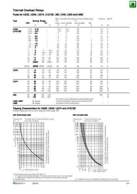
Thermal Thermal Thermal Overload Overload Relays Relays Fuses Fuses for for U3/32, U3/32, U3/42, U3/42, U3/74, U3/74, U12/16E, U12/16E, U85, U85, U180, U180, U320 U320 and and U800 U800 Max. Fuse Size According to Coordination-type Fuse UL SCCR Type Type Setting Setting Range Range "2" 1) "1" 1) DOL DOL quick slow, gL(gG) slow, gL(gG) aM A A A A A A A kA U3/32 U3/32 U3/32 0,12 - 0,18 0,18 - 0,5 2) 0,5 2) 25 - 15 5 (U12/16E) (U12/16E) 0,18 - 0,27 0,27 - 1,0 2) 1,0 2) 25 - 15 5 0,27 - 0,4 0,4 - 2 2 25 - 15 5 0,4 - 0,6 0,6 - 2 2 25 - 15 5 0,6 - 0,9 0,9 - 4 4 25 - 15 5 0,8 - 1,2 1,2 - 4 4 25 2 15 5 1,2 - 1,8 1,8 - 6 6 25 2 15 5 1,8 - 2,7 2,7 - 10 10 25 4 15 5 2,7 - 4 - 16 10 25 4 15 5 4 - 6 7 - 10,5 20 16 25 6 15 5 6 - 9 10,5 - 15,5 35 25 35 10 25 5 8 - 11 11 14 - 19 35 25 35 16 30 5 10 - 14 14 18 - 24 50 35 63 16 40 5 13 - 18 18 23 - 31 50 35 63 20 50 5 17 -(23)24 (23)24 30 -(40)41 63 50 63 25 60 5 (22)23 -(30)32 (30)32 (38)40 -(52)55 80 63 80 35 70 5 U3/42 U3/42 U3/42 10 - 14 14 18 - 24 50 35 80 16 40 5 14 - 20 20 24 - 35 63 50 80 25 60 5 20 - 28 28 35 - 48 80 63 80 35 80 5 28 - 42 42 48 - 73 100 80 150 50 110 5 U3/74 U3/74 U3/74 20 - 28 28 35 - 48 100 80 150 35 80 5 28 - 42 42 42 48 - 73 125 100 150 50 110 5 40 - 52 52 70 - 90 160 100 150 63 200 5 52 - 65 65 90 - 112 160 125 150 80 250 10 60 - 74 74 104 - 128 160 125 150 80 250 10 U85 U85 U85 60 - 90 90 104 - 156 300 10 80 -120 120 140 - 207 - 10 U180, U180, U180, U320 U320 all ranges For short circuit protecting overload relays with current transformer use fuse according to the - - U800 U800 all ranges contactor of the combination. - - Tripping Tripping Characteristics Characteristics for for for U3/32, U3/32, U3/32, U3/42, U3/42, U3/42, U3/74 U3/74 and and U12/16E U12/16E Detailed tripping times for each range see table page 106 with with three-phase three-phase load load Tripping time (Average value of typical tolerance curves min. s from cold condition) F. L. C. multiplication factor Proceeding from service condition the times decrease to 20-30% of the characteristic values with with two-pole two-pole load load Tripping time (Typical tolerance curve min. s from cold condition) 1) Coordination-type according to IEC 947-4-1: "2": Light contact welding accepted. Thermal overload relay must not be damaged. "1": Welding of contactor and damage of the thermal overload relay allowed. 2) Miniature fuse 3) Suitable for use on a capability of delivering not more than D677E 107 Proceeding from service condition the times decrease to 70-80% of the characteristic values K =Imax /Ie Imax = max. phase current Ie = max. scale value