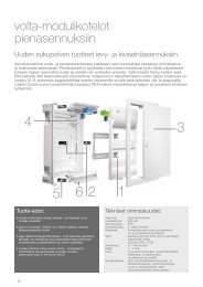
Index Page General 2 Approvals 3 Technical Information 5 Mounting ...
Index Page General 2 Approvals 3 Technical Information 5 Mounting ...
Index Page General 2 Approvals 3 Technical Information 5 Mounting ...

You also want an ePaper? Increase the reach of your titles
YUMPU automatically turns print PDFs into web optimized ePapers that Google loves.
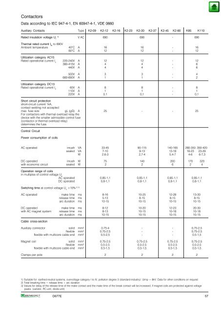
Contactors<br />
Data according to IEC 947-4-1, EN 60947-4-1, VDE 0660<br />
Auxiliary Contacts Type K2-09 K2-12 K2-16 K2-23 K2-30 K2-37 K2-45 K2-60 K85 K110<br />
Rated insulation voltage U i 1) V AC 690 690 - 690<br />
Thermal rated current I th to 690V<br />
Ambient temperature 40°C A 16 16 - 16<br />
60°C A 12 12 - 12<br />
Utilization category AC15<br />
Rated operational current I e 220-240V A 12 12 - 12<br />
380-415V A 4 4 - 6<br />
440V A 4 4 - 6<br />
500V A 3 3 - 4<br />
660-690V A 1 1 - 2<br />
Utilization category DC13<br />
Rated operational current I e 60V A 8 8 - 8<br />
110V A 1 1 - 1<br />
220V A 0,1 0,1 - 0,1<br />
Short circuit protection<br />
short-circuit current 1kA,<br />
contact welding not accepted<br />
max. fuse size gL (gG) A 25 - - 25<br />
For contactors with thermal overload relay the<br />
device with the smaller admissible control fuse<br />
(contactor or thermal overload relay)<br />
determines the fuse.<br />
Control Circuit<br />
Power consumption of coils<br />
AC operated inrush VA 33-45 90-115 140-165 280-350 350-420<br />
sealed VA 7-10 9-13 13-18 16-23 23-29<br />
W 2,6-3 2,7-4 5,4-7 4-6 6-7,3<br />
DC operated inrush W 75 140 200 170 320<br />
with economic circuit sealed W 2 2 6 2 4<br />
Operation range of coils<br />
in multiples of control voltage U s<br />
AC operated 0,85-1,1 0,85-1,1 0,85-1,1 0,85-1,1<br />
DC operated 0,8-1,1 0,8-1,1 0,8-1,1 0,8-1,1<br />
2) 3)<br />
Switching time at control voltage U ±10% s<br />
AC operated make time ms 8-16 10-25 12-28 13-30<br />
release time ms 5-13 8-15 8-15 8-15<br />
arc duration ms 10-15 10-15 10-15 10-15<br />
DC operated make time ms 8-12 10-20 12-23 20-30<br />
with AC magnet system release time ms 8-13 10-15 10-18 10-18<br />
arc duration ms 10-15 10-15 10-15 10-15<br />
Cable cross-section<br />
Auxiliary connector solid mm² 0,75-4 - - 0,75-2,5<br />
flexible mm² 0,75-2,5 - - 0,75-2,5<br />
flexible with multicore cable end mm² 0,5-2,5 - - 0,5-1,5<br />
Magnet coil solid mm² 0,75-2,5 0,75-2,5 0,75-2,5 0,75-2,5<br />
flexible mm² 0,5-2,5 0,5-2,5 0,5-2,5 0,5-2,5<br />
flexible with multicore cable end mm² 0,5-1,5 0,5-1,5 0,5-1,5 0,5-1,5<br />
Clamps per pole 2 2 2 2<br />
1) Suitable for: earthed-neutral systems, overvoltage category I to IV, pollution degree 3 (standard-industry): Uimp = 8kV. Data for other conditions on request<br />
2) Total breaking time = release time + arc duration<br />
3) Values for delay of the release time of the make contact and the make time of the break contact will be increased, if magnet coils are protected against voltage<br />
peaks (varistor, RC-unit, diode-unit)<br />
D677E 57