standard & heavy duty line
standard & heavy duty line
standard & heavy duty line

You also want an ePaper? Increase the reach of your titles
YUMPU automatically turns print PDFs into web optimized ePapers that Google loves.
K<br />
K<br />
001<br />
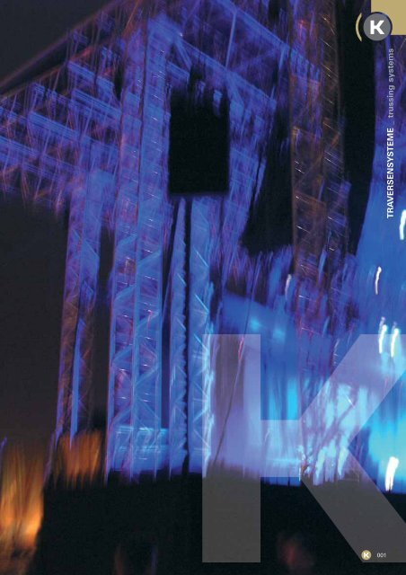
TRAVERSENSYSTEME _ trussing systems
K<br />
Responsibility<br />
002<br />
This catalogue has been produced with the purpose of presenting<br />
some of the many uses of the products, however there are many more<br />
possibilities for every single model. The detailed technical reports are<br />
available on separate publications or downloadable from our web site.<br />
K
K<br />
K<br />
Responsibility in thinking and designing. Responsibility in producing,<br />
testing, verifying. Responsibility in learning, understanding and training.<br />
Responsibility in giving what you need on time. Responsibility in giving<br />
answers.<br />
Building truss is a great responsibility. First and foremost we must guarantee<br />
safety. We understand this responsibility and this makes us focus<br />
on the attention to detail.<br />
Over half the products shown in this catalogue have been updated from<br />
last year, still ensuring the compatibility with the previous <strong>line</strong>s.<br />
Aluminium products are now used in many varied applications, and the<br />
different needs of our users drive us to offer an increasing range of<br />
models.<br />
Our aim is to provide the right solution for every situation, with the most<br />
suitable product. Our ever increasing range of products is a responsibility<br />
we have embraced over the last ten years since we produced our first<br />
truss.<br />
This responsibility is manufactured into every product we make.<br />
Alongside the guarantee of high quality manufacturing processes and<br />
testing procedures, lies the dedication and the passion of people who<br />
love their job. To give you everything you need before you even know<br />
you need it!<br />
Verantwortung im Denken und Gestalten. Verantwortung in der<br />
Produktion, beim Testen und Prüfen. Verantwortung im Lernen,<br />
Verstehen und Trainieren. Verantwortung, Ihnen ’just in time’ das zu<br />
liefern, was Sie benötigen. Verantwortung in unseren Antworten.<br />
Traversen zu bauen, ist eine sehr verantwortungsvolle Tätigkeit.<br />
Vor allem bedeutet es, Sicherheit zu garantieren. Wir verstehen diese<br />
Verantwortung und sie motiviert uns, dass wir uns jedem Detail mit<br />
Aufmerksamkeit widmen.<br />
Mehr als die Hälfte der in diesem Katalog gezeigten Produkte wurden<br />
gegenüber dem Vorjahr überarbeitet; dennoch bleibt die Kompatibilität<br />
zu älteren Serien gewährleistet.<br />
Produkte aus Aluminium werden heutzutage für die unterschiedlichsten<br />
Zwecke genutzt und die individuellen Bedürfnisse unserer Anwender<br />
sind uns ein Ansporn, immer neue Modelle zu entwickeln.<br />
Unser Ziel ist es, für jede Situation die richtige Lösung mit dem<br />
geeignetsten Produkt anzubieten.<br />
Unsere stetig wachsende Modellpalette ist eine Verantwortung, die wir<br />
in den vergangenen zehn Jahren angenommen haben, seit die erste<br />
Traverse unsere Firma verließ.<br />
Diese Verantwortung fließt in jedes von uns gefertigte Produkt mit ein.<br />
So wird unser Versprechen auf hochwertige Produktions- und<br />
Testverfahren erst durch die Hingabe und Leidenschaft von Menschen<br />
komplett, die ihre Arbeit lieben. Um Ihnen alles zu geben, was Sie<br />
brauchen, noch ehe Sie wissen, dass Sie es brauchen!<br />
www.vitecgroup.com<br />
003
K<br />
A convenient solution<br />
ALUMINIUM TRUSSES:<br />
A CONVENIENT SOLUTION<br />
Aluminium trusses have been<br />
used by technicians in theatres,<br />
television studios and at rock<br />
concerts for some time now.<br />
Today however they are spreading<br />
to all sectors where structures<br />
have to built for hanging lights,<br />
equipment, false ceiling, etc.<br />
They are aesthetically pleasing,<br />
light and sturdy, and can also be<br />
used to build fair stands, in<br />
showroom, in shops, in modern<br />
cinemas, in entertainment<br />
establishments, in large sports<br />
complexes, to support large<br />
advertising panels, and in<br />
multipurpose halls such as<br />
railway and airport concourses.<br />
In this catalogue, Litec offers a<br />
vast range of products and<br />
structures designed to meet the<br />
needs of workers in various<br />
different sectors.<br />
ALUTRAVERSEN:<br />
EINE PRAKTISCHE LÖSUNG<br />
Alutraversen werden schon seit<br />
geraumer Zeit von Technikern in<br />
Theatern, Fernsehstudios und bei<br />
Rockkonzerten eingesetzt.<br />
Inzwischen erobern sie jedoch all<br />
jene Bereiche, wo die hängende<br />
Montage von Scheinwerfern,<br />
Lautsprechern, Zwischendecken<br />
usw. verlangt wird. Sie sind<br />
ästhetisch ansprechend, leicht<br />
und stabil und können auch zum<br />
Bau von Messeständen, in<br />
Showrooms und Ladengeschäften,<br />
in modernen Kinos,<br />
Unterhaltungsbetrieben und<br />
Sportanlagen zur Präsentation<br />
großer Werbetafeln, aber auch in<br />
Mehrzweck- und Bahnhofshallen<br />
oder Flughafenterminals<br />
eingesetzt werden.<br />
In diesem Katalog stellt Litec<br />
seine breit gefächerte Auswahl an<br />
Produkten und Konstruktionen vor,<br />
die alle mit dem Ziel entwickelt<br />
wurden, den Bedürfnissen von<br />
Praktikern in den unterschiedlichsten<br />
Bereichen Rechnung zu tragen.<br />
004<br />
K<br />
1 2<br />
4<br />
2 5<br />
1 - Ice Disco at the O2 - Greenwich, London, Courtesy of: A.C. Lighting Ltd., UK<br />
2 - Eurovision Song Festival, Macedonia, Courtesy of: Infomedia Sistemi – Skopje Macedonia<br />
3 - mpZero Tour, Courtesy of: Stage System S.r.l. – Milano, Italy<br />
5
7<br />
4 - Hala Stulecia, Wrocław, Courtesy of: Show Design – Trzebnica, Polonia<br />
5 - BBC – The Underdog Show, Courtesy of: A.C. Lighting Ltd., UK<br />
6 - Bocelli Live @ Teatro del Silenzio, Lajatico, Courtesy of: Stage System S.r.l. – Milano, Italia<br />
3<br />
6<br />
K<br />
K<br />
005
K<br />
1-Ice Disco at The O2 – Greenwich, London<br />
Courtesy of: A.C. Lighting Ltd., UK<br />
2-Total Request Live (TRL) Tour<br />
Courtesy of:<br />
Stage System S.r.l. – Milano, Italy<br />
3-Bahrain Financial Harbour<br />
Courtesy of:<br />
TechnoPro l.l.c. – Dubai, Emirates<br />
4-Ramazzotti European Tour,<br />
Courtesy of: Stage System S.r.l.<br />
Milano, Italy<br />
5-Salone Nautico di Genova<br />
Courtesy of:<br />
Studio Due Group – Treviso, Italiy<br />
6-Heineken Jammin' Festival<br />
Courtesy of:<br />
Stage System S.r.l. – Milano, Italiy<br />
7-Fashion Show, Louis Vuitton<br />
Courtesy of:<br />
JLT Services – Parigi, France<br />
Copyright Design & Production<br />
La Mode en Image, realisation<br />
JLT Services<br />
Photo Oliver Sochard<br />
006<br />
K<br />
1<br />
2<br />
5 6<br />
2<br />
4
3<br />
7<br />
K<br />
K<br />
007
K<br />
Contents<br />
Quality and Safety. . . . . . . . . . . . . . . . . . . . . . . . . . . . . . . . . . . . . . . . . . . 010<br />
Tested. . . . . . . . . . . . . . . . . . . . . . . . . . . . . . . . . . . . . . . . . . . . . . . . . . . . . . . . . . . . . . . . 011<br />
QB20 - TB20 - FB20 . . . . . . . . . . . . . . . . . . . . . . . . . . . . . . . . . . . . . . . 012<br />
Accessories . . . . . . . . . . . . . . . . . . . . . . . . . . . . . . . . . . . . . . . . . . . . . . . . . . . . . 013<br />
Accessories - Dado Display . . . . . . . . . . . . . . . . . . . . . . . . . . 015<br />
The “S” Series. . . . . . . . . . . . . . . . . . . . . . . . . . . . . . . . . . . . . . . . . . . . . . . . . 016<br />
Connection Systems . . . . . . . . . . . . . . . . . . . . . . . . . . . . . . . . . . . . . . . 017<br />
QX25S . . . . . . . . . . . . . . . . . . . . . . . . . . . . . . . . . . . . . . . . . . . . . . . . . . . . . . . . . . . . . . . 018<br />
QX30S . . . . . . . . . . . . . . . . . . . . . . . . . . . . . . . . . . . . . . . . . . . . . . . . . . . . . . . . . . . . . . . 020<br />
QD30S - QD30SA . . . . . . . . . . . . . . . . . . . . . . . . . . . . . . . . . . . . . . . . . . . . . 022<br />
QX40S . . . . . . . . . . . . . . . . . . . . . . . . . . . . . . . . . . . . . . . . . . . . . . . . . . . . . . . . . . . . . . . 024<br />
QD40S - QD40SA . . . . . . . . . . . . . . . . . . . . . . . . . . . . . . . . . . . . . . . . . . . . . 026<br />
Square Corners and Fittings . . . . . . . . . . . . . . . . . . . . . . . . 028<br />
008<br />
K<br />
Dado K8 . . . . . . . . . . . . . . . . . . . . . . . . . . . . . . . . . . . . . . . . . . . . . . . . . . . . . . . . . . . . 029<br />
TX25S . . . . . . . . . . . . . . . . . . . . . . . . . . . . . . . . . . . . . . . . . . . . . . . . . . . . . . . . . . . . . . . . 030<br />
TX30S . . . . . . . . . . . . . . . . . . . . . . . . . . . . . . . . . . . . . . . . . . . . . . . . . . . . . . . . . . . . . . . . 032<br />
TX40S . . . . . . . . . . . . . . . . . . . . . . . . . . . . . . . . . . . . . . . . . . . . . . . . . . . . . . . . . . . . . . . . 034<br />
Triangular Corners and Fittings . . . . . . . . . . . . . . . . . . . 036<br />
FX25S - FX30S - FX40S. . . . . . . . . . . . . . . . . . . . . . . . . . . . . . . . . . 038<br />
Flat Corners and Fittings. . . . . . . . . . . . . . . . . . . . . . . . . . . . . . . 040<br />
Dado K4 / K2. . . . . . . . . . . . . . . . . . . . . . . . . . . . . . . . . . . . . . . . . . . . . . . . . . . . 041<br />
Rings . . . . . . . . . . . . . . . . . . . . . . . . . . . . . . . . . . . . . . . . . . . . . . . . . . . . . . . . . . . . . . . . . 042<br />
Wincher . . . . . . . . . . . . . . . . . . . . . . . . . . . . . . . . . . . . . . . . . . . . . . . . . . . . . . . . . . . . 044<br />
Towerlift 3. . . . . . . . . . . . . . . . . . . . . . . . . . . . . . . . . . . . . . . . . . . . . . . . . . . . . . . . 045<br />
Unitower. . . . . . . . . . . . . . . . . . . . . . . . . . . . . . . . . . . . . . . . . . . . . . . . . . . . . . . . . . . 046<br />
Varitower 2. . . . . . . . . . . . . . . . . . . . . . . . . . . . . . . . . . . . . . . . . . . . . . . . . . . . . . 048
Flyintower Compact . . . . . . . . . . . . . . . . . . . . . . . . . . . . . . . . . . . . . . . 050<br />
Flyintower X30/D30 . . . . . . . . . . . . . . . . . . . . . . . . . . . . . . . . . . . . . . . 051<br />
Arc Roofing Systems. . . . . . . . . . . . . . . . . . . . . . . . . . . . . . . . . . . . . . 052<br />
Double Pitch Roofing Systems . . . . . . . . . . . . . . . . . . . . . 056<br />
QL40A. . . . . . . . . . . . . . . . . . . . . . . . . . . . . . . . . . . . . . . . . . . . . . . . . . . . . . . . . . . . . . . . 064<br />
QL52 - QL52A . . . . . . . . . . . . . . . . . . . . . . . . . . . . . . . . . . . . . . . . . . . . . . . . . . 066<br />
RL76 - RL76A . . . . . . . . . . . . . . . . . . . . . . . . . . . . . . . . . . . . . . . . . . . . . . . . . . 068<br />
QL76PR . . . . . . . . . . . . . . . . . . . . . . . . . . . . . . . . . . . . . . . . . . . . . . . . . . . . . . . . . . . . . 070<br />
Maxitower 40 . . . . . . . . . . . . . . . . . . . . . . . . . . . . . . . . . . . . . . . . . . . . . . . . . 072<br />
Maxitower 52 . . . . . . . . . . . . . . . . . . . . . . . . . . . . . . . . . . . . . . . . . . . . . . . . . 073<br />
Maxitower 76 . . . . . . . . . . . . . . . . . . . . . . . . . . . . . . . . . . . . . . . . . . . . . . . . . 074<br />
Flyintower L52V . . . . . . . . . . . . . . . . . . . . . . . . . . . . . . . . . . . . . . . . . . . . . . 075<br />
Libera . . . . . . . . . . . . . . . . . . . . . . . . . . . . . . . . . . . . . . . . . . . . . . . . . . . . . . . . . . . . . . . . 076<br />
Libera Truss . . . . . . . . . . . . . . . . . . . . . . . . . . . . . . . . . . . . . . . . . . . . . . . . . . . . . 080<br />
Libera Grid . . . . . . . . . . . . . . . . . . . . . . . . . . . . . . . . . . . . . . . . . . . . . . . . . . . . . . . 081<br />
Libera Roof 52 . . . . . . . . . . . . . . . . . . . . . . . . . . . . . . . . . . . . . . . . . . . . . . . . 084<br />
Libera Roof 76 . . . . . . . . . . . . . . . . . . . . . . . . . . . . . . . . . . . . . . . . . . . . . . . . 086<br />
Libera Roof 105 . . . . . . . . . . . . . . . . . . . . . . . . . . . . . . . . . . . . . . . . . . . . . . 088<br />
Libera Roof Tunnel. . . . . . . . . . . . . . . . . . . . . . . . . . . . . . . . . . . . . . . . . . 090<br />
Alusfera . . . . . . . . . . . . . . . . . . . . . . . . . . . . . . . . . . . . . . . . . . . . . . . . . . . . . . . . . . . . 092<br />
Terrace Stand Roofing . . . . . . . . . . . . . . . . . . . . . . . . . . . . . . . . . . . 094<br />
Cablecross . . . . . . . . . . . . . . . . . . . . . . . . . . . . . . . . . . . . . . . . . . . . . . . . . . . . . . . 096<br />
LiteCad . . . . . . . . . . . . . . . . . . . . . . . . . . . . . . . . . . . . . . . . . . . . . . . . . . . . . . . . . . . . . . 098<br />
K<br />
K<br />
009
K<br />
Quality and Safety<br />
There are different levels of<br />
quality when talking about<br />
aluminium trusses.<br />
There is the quality of the raw<br />
material, the quality of welding<br />
and the quality on the<br />
manufacturing process.<br />
A product or brand may be<br />
perceived as "good quality", but<br />
this opinion alone is not enough<br />
to make the product safe, strong<br />
and durable.<br />
Litec products are made to comply<br />
with all the relevant international<br />
<strong>standard</strong>s and they are tested and<br />
certified by the most respectable<br />
certification institutes.<br />
Only this level of detail, can<br />
generate high quality, strong and<br />
safe truss systems.<br />
"High quality equals safety"<br />
Zum Thema Alutraversenbau<br />
existieren unterschiedliche<br />
Qualitäts-Gütesiegel.<br />
Da wären zunächst die Qualität<br />
des Rohmaterials, der<br />
Schweißarbeiten und des<br />
Herstellungsverfahrens zu nennen.<br />
Ein Produkt oder eine Marke mag<br />
zwar als ’qualitativ hochwertig’<br />
empfunden werden, jedoch genügt<br />
diese Meinung allein nicht, um ein<br />
Produkt sicher, stabil und langlebig<br />
zu machen.<br />
Wir fertigen unsere Litec-Produkte<br />
mit der Vorgabe, dass sie allen<br />
relevanten internationalen<br />
Sicherheitsnormen entsprechen;<br />
zudem werden sie von den angesehensten<br />
Prüfinstituten getestet<br />
und zertifiziert.<br />
Nur diese Sorgfalt im Detail kann<br />
stabile und sichere<br />
Traversensysteme von solch hoher<br />
Qualität hervorbringen.<br />
“Hohe Qualität bedeutet<br />
Sicherheit.“<br />
010<br />
K<br />
The majority of our trusses are tested and certified by TÜV SÜD of<br />
München (Germany).<br />
Die Mehrzahl unserer Traversen werden vom TÜV Süd in München<br />
getestet und zertifiziert.<br />
SLV München, who certifies quality of welding in accordance with<br />
DIN V 4113-3, awarded Litec the permit for welding together our<br />
aluminium casting plate to aluminium alloy EN AW 6082 T6.<br />
SLV is part of the international association of welding techniques<br />
GSI (Gesellschaft für Schweißtechnisk International).<br />
Die SLV München, welche die Qualität von Schweißarbeiten nach DIN V<br />
4113-3 bescheinigt, hat Litec die Genehmigung erteilt, unsere<br />
Alugussplatte mit der Aluminium-Legierung nach EN AW 6082 T6 zu verschweißen.<br />
Die SLV ist eine Abteilung der Gesellschaft für Schweißtechnik<br />
International (GSI).<br />
European quality welding certification has been obtained by SLV of<br />
Fellbach, which is part of DVS Zert, a department of the German<br />
Welding Society.<br />
Das Europäische Gütesiegel für Schweißtechnik wurde von der SLV<br />
Fellbach erteilt, einer Abteilung der DVS Zert, die wiederum zur<br />
Deutschen Gesellschaft für Schweißtechnik gehört.<br />
Litec holds the International quality welding certification (ISO 3834)<br />
from EWF, the European Welding Federation. EWF is an international<br />
Authorised National Body for Company Certification.<br />
Litec ist Inhaber des Internationalen Gütesiegels für Schweißtechnik<br />
(ISO 3834) der Europäischen Gesellschaft für Schweißtechnik (EWF).<br />
Load tests, traction and bending tests and destructive tests are carried<br />
out in collaboration with Dipartimento di Costruzioni e Trasporti at the<br />
University of Padova.
Tested<br />
Litec has introduced the concept<br />
of double connection cast<br />
aluminium plate since 1995.<br />
This <strong>line</strong> of Products has been<br />
re-designed, now including a new<br />
end plate, produced from an<br />
aluminium alloy reinforced by a<br />
process of heat treatment.<br />
Litec is certified by SLV Munchen<br />
in accordance with DIN V 4113-3.<br />
Litec DIN V 4113-3 Certification<br />
class is C, the more restrictive.<br />
Litec hat schon 1995 das Prinzip<br />
der Doppelverbindungs-<br />
Alugussplatte eingeführt.<br />
Diese Produktlinie wurde überarbeitet<br />
und besitzt jetzt eine neue<br />
Endplatte aus einer durch<br />
Wärmebehandlung verstärkten<br />
Aluminiumlegierung.<br />
Litec ist von der SLV München<br />
nach DIN V 4113-3 zertifiziert,<br />
und zwar gemäß der strengeren<br />
C-Klassifizierung.<br />
EN 573-3: Aluminium and aluminium alloys.<br />
Chemical composition and from of wrought products.<br />
Chemical composition.<br />
EN 755-2: Aluminium and aluminium alloys -<br />
Extruded rod/bar, tube and profiles - Mechanical<br />
properties.<br />
EN 1706: Aluminium and aluminium alloys - Castings<br />
- Chemical composition and mechanical properties.<br />
EN 10277-3: Bright steel products - Technical delivery<br />
conditions - Free-cutting steels.<br />
EN 10204: Metallic products - Types of inspection<br />
documents.<br />
EN 1990: Eurocode - Basis of structural design.<br />
ENV 1999-1-1: Eurocode 9 - Design of aluminium<br />
structures - Part 1-1: General rules - General rules<br />
and rules for buildings.<br />
DIN 4113-1: Aluminium constructions under predominantly<br />
static loading; static analysis and structural<br />
design.<br />
DIN 4113-2: Aluminium constructions under predominantly<br />
static loading - Part 2: Static analysis, structural<br />
design and execution of welded constructions.<br />
DIN V 4113-3: Aluminium constructions under predominantly<br />
static loading - Part 3: Execution and<br />
qualification of constructors.<br />
BS 8118-1: Structural use of aluminium. Code of<br />
practice for design.<br />
BS 7905-2: Lifting equipment for performance,<br />
broadcast and similar applications. Specification for<br />
design and manufacture of aluminium and steel<br />
trusses and towers.<br />
BS 7906-2: Lifting equipment for performance,<br />
broadcast and similar applications. Code of practice<br />
for use of aluminium and steel trusses and<br />
towers.<br />
EN ISO 12100-2: Safety of machinery - Basic concepts,<br />
general principles for design - Part 2:<br />
Technical principles.<br />
EN ISO 9606-2: Qualification test of welders - Fusion<br />
welding - Part 1: Aluminium and aluminium alloys.<br />
EN ISO 15614-1: Specification and qualification of<br />
welding procedures for metallic materials - Welding<br />
procedure test - Part 1: Arc and gas welding of<br />
steels and arc welding of nickel and nickel alloys.<br />
EN ISO 15614-2: Specification and qualification of<br />
welding procedures for metallic materials - Welding<br />
procedure test - Part 2: Arc welding of aluminium<br />
and its alloys.<br />
EN 729-2: Quality requirements for welding. Fusion<br />
welding of metallic materials. Comprehensive quality<br />
requirements.<br />
EN ISO 3834-2: Quality requirements for fusion welding<br />
of metallic materials. Comprehensive quality<br />
requirements.<br />
EN 30042: Arc-welded joints in aluminium and its<br />
weldable alloys. Guidance on quality levels for<br />
imperfections.<br />
EN 13018: Non-destructive testing - Visual testing -<br />
General principles.<br />
K<br />
K<br />
011
K<br />
QB20 - TB20 - FB20<br />
All Display series trusses are<br />
made with 35 mm diameter arc<br />
welded aluminium lengthwise<br />
tubes which ensure great<br />
sturdiness and a particularly<br />
low weight.<br />
The structures are available with<br />
square, triangular and flat<br />
sections. All have 20 cm sides.<br />
The basic finish is polished<br />
aluminium; other RAL colour<br />
finishes are available on request.<br />
The trusses are connected using<br />
a system of expansion pins which<br />
are fixed with an allen wrench. All<br />
the 90° corners are made using<br />
the modular Display Dado system.<br />
Alle Traversen der Display-Serie<br />
werden aus elektrogeschweißten<br />
Aluminium-Gurtrohren mit 35 mm<br />
Rohrdurchmesser gefertigt, was<br />
hohe Stabilität mit besonders<br />
niedrigem Gewicht verbindet.<br />
Erhältlich sind 2-/ 3- und 4-Punkt<br />
Elemente mit jeweils 20 cm<br />
Seitenlänge. Standardfinish ist<br />
Aluminium poliert, auf Wunsch<br />
sind jedoch auch andere<br />
Oberflächen nach RAL lieferbar.<br />
Die Verbindung der Traversenstücke<br />
erfolgt mit Spreizpins, die<br />
mit einem Inbusschlüssel fixiert<br />
werden. Alle 90°-Winkel werden<br />
mit Hilfe des modularen Display<br />
Dado-Systems aufgebaut.<br />
012<br />
K<br />
QB20<br />
B<br />
B<br />
FB20<br />
TB20<br />
A<br />
A<br />
B 200<br />
A<br />
Code<br />
TRUSS - QB20<br />
Dimensions (cm) Weight (Kg)<br />
QB20060 20x20x60 0.87<br />
QB20080 20x20x80 1.17<br />
QB20100 20x20x100 1.47<br />
QB20160 20x20x160 2.35<br />
QB20200 20x20x200 2.97<br />
QB20300 20x20x300 4.46<br />
TRUSS - TB20<br />
TB20060 20x17.8x60 0.65<br />
TB20080 20x17.8x80 0.88<br />
TB20100 20x17.8x100 1.10<br />
TB20160 20x17.8x160 1.76<br />
TB20200 20x17.8x200 2.22<br />
TB20300 20x17.8x300 3.35<br />
200<br />
200<br />
DISPLAY TRUSS<br />
178<br />
Code<br />
TRUSS - FB20<br />
Dimensions (cm) Weight (Kg)<br />
FB20060 20x3.5x60 0.43<br />
FB20080 20x3.5x80 0.59<br />
FB20100 20x3.5x100 1.10<br />
FB20160 20x3.5x160 1.76<br />
FB20200 20x3.5x200 2.22<br />
FB20300 20x3.5x300 2.23<br />
CORNERS<br />
QB20K8 (Dado) 20x20x20 0,13<br />
FB20K4 (Dado) 20x20x3.5 1.10<br />
FB20K2 (Dado) 20x3.5x3.5 0.40<br />
DTKL 3.5x3.5x8.2 0.25<br />
DTKS 3.5x3.5x2.2 0.08<br />
DTK01 3.5x3.5x3.5 0.10
Accessories<br />
QB20<br />
Square section aluminium truss<br />
with 20 cm long sides.<br />
(A) Lengthwise: HF seam welded<br />
tube, ø35x1 mm EN AW 5086 H36<br />
(B) Diagonals: HF seam welded<br />
tube, ø10x1 mm EN AW 5086 H36<br />
Connection system:<br />
DT020 expansion connector<br />
TB20<br />
Triangular section aluminium truss<br />
with 20 cm long sides.<br />
(A) Lengthwise: HF seam welded<br />
tube, ø35x1 mm EN AW 5086 H36<br />
(B) Diagonals: HF seam welded<br />
tube, ø10x1 mm EN AW 5086 H36<br />
Connection system:<br />
DT020 expansion connector<br />
FB20<br />
Flat section aluminium truss with<br />
20 cm long sides.<br />
(A) Lengthwise: HF seam welded<br />
tube, ø35x1 mm EN AW 5086 H36<br />
(B) Diagonals: HF seam welded<br />
tube, ø10x1 mm EN AW 5086 H36<br />
Connection system:<br />
DT020 expansion connector<br />
There is a wide range of<br />
accessories which allow<br />
countless construction uses.<br />
Most of them are highly<br />
attractive top quality die-cast<br />
components.<br />
DT020 Tube connector<br />
DT013 Panel clamp<br />
DT035 Superclamp<br />
DISPLAY TRUSS<br />
DT020 DT004<br />
DT014<br />
DT013 DT013C<br />
DT093<br />
DT035 SUPERCLAMP DT045<br />
DT034<br />
DT004 Tee clamp<br />
DT013C Fixture clamp<br />
DT045 Articulated joint 180°<br />
DT014 Parallel clamp<br />
DT093 Large cable clip<br />
DT034W Rubber sucker white<br />
DT034B Rubber sucker black<br />
K<br />
K<br />
013
K<br />
Accessories<br />
The structures may be fixed to the<br />
ground or walls with plugs or<br />
rubber feet, or mounted on wheels<br />
or adjustable feet.<br />
The DT021 adapter module acts<br />
as an interface for all screw-on<br />
accessories.<br />
Die Rohrkonstruktionen können<br />
über Befestigungsplatten oder<br />
Gummifüße auf dem Boden oder<br />
an Wänden befestigt werden;<br />
alternativ sind auch Laufrollen<br />
oder höhenverstellbare Füße montierbar.<br />
Das Adapter-Modul DT021 dient<br />
als Endstück für alle Zubehörteile<br />
mit Schraubanschluss.<br />
DT021 Foot adapter<br />
DT022 Adjustable foot<br />
DT015B Rubber tube foot Black<br />
DT015W Rubber tube foot White<br />
DT104 Wheel with brake, ø 75 mm<br />
014<br />
K<br />
DISPLAY TRUSS<br />
DT021 DT022 DT015<br />
DT104
Dado Display<br />
Dado Display is the simplest way<br />
to create 90° corners on all<br />
Display <strong>line</strong> trusses, including<br />
triangular section trusses.<br />
As shown in the examples,<br />
it is also possible to fit<br />
components with different<br />
sections together and use them<br />
in the same structure.<br />
Triangular trusses can be used to<br />
form corners or crosses, again<br />
with Dado K4, together with one<br />
or more KL or KS components.<br />
Dado Display stellt die einfachste<br />
Lösung dar, um bei allen<br />
Traversen der Display-Serie – auch<br />
bei Dreipunkt-Traversen –<br />
90°-Ecken zu realisieren. Wie in<br />
den Beispielen gezeigt, lassen<br />
sich sogar Elemente unterschiedlicher<br />
Größe kombinieren und in<br />
dieselbe Konstruktion einfügen.<br />
Mit Dreipunkt-Traversen können<br />
ebenfalls unter Verwendung von<br />
Dado K4 sowie einem oder<br />
mehreren KL- oder KS-Elementen<br />
Winkel oder Kreuzungen gestaltet<br />
werden.<br />
QB20K8 Basic configurable 2<br />
to 6 way module<br />
FB20K4 Basic configurable 2<br />
to 6 way module<br />
FB20K2 Basic configurable 2<br />
to 4 way module<br />
DTKL Long compensatory<br />
module for TB series<br />
DTKS Short compensatory<br />
module for TB series<br />
DTK01 Six-faced cube for<br />
Display <strong>line</strong><br />
DISPLAY TRUSS<br />
QB20K8 FB20K4<br />
FB20K2<br />
DTKL/DTKS/DTK01<br />
K<br />
K<br />
015
K<br />
New “S” Series<br />
The popular end plate system has<br />
a new design, produced from a<br />
new aluminium alloy that is heat<br />
treated to ensure even greater<br />
strength and provide a bright<br />
polished appearance.<br />
The diagonal chords have been<br />
re-configured and their diameter<br />
changed to improve the aesthetic<br />
appearance and increase the<br />
overall strength of the truss.<br />
The new “S” series trusses still<br />
employ the same dual connection<br />
systems of bolt kits or Fast<br />
connection kits as the existing<br />
range, to ensure full compatibility<br />
between the <strong>line</strong>s.<br />
The two systems maybe used as<br />
alternatives to each other, but if<br />
the structures are to be used near<br />
their limits, we recommend using<br />
the quick-fit system. The bolt<br />
connection has lower loading<br />
capacity than shown in our<br />
reference tables.<br />
Das populäre Endplatten-System<br />
kommt im veränderten Design. Als<br />
Material dient eine neue<br />
Aluminiumlegierung, die dank<br />
Wärmebehandlung noch stabiler<br />
ist und mit ihrem Hochglanzlook<br />
einfach klasse aussieht.<br />
Die Diagonalstreben wurden neu<br />
gestaltet und im Durchmesser<br />
angepasst, um das ästhetische<br />
Erscheinungsbild der Traverse<br />
aufzuwerten und ihre<br />
Gesamtbelastbarkeit zu erhöhen.<br />
Die Traversen der neuen ’S’-Serie<br />
verwenden das gleiche<br />
Doppelverbinder-Prinzip mit<br />
Schraub- oder Fast Connection-<br />
Kits wie die Vorgängerserie, damit<br />
die volle Kompatibilität zwischen<br />
beiden Serien erhalten bleibt.<br />
Die beiden Systeme können alternativ<br />
verwendet werden; falls die<br />
Aufbauten nahe ihrer<br />
Belastbarkeitsgrenze betrieben<br />
werden sollen, empfehlen wir<br />
jedoch den Einsatz des Quick-fit-<br />
Systems. Die Verbindung mit<br />
Schrauben weist eine geringere<br />
Tragleistung auf als in unseren<br />
Referenztabellen aufgeführt.<br />
016<br />
K<br />
The plates allow two different types of connection: quick-fit and<br />
with bolts. The connection systems are available in kits which<br />
consist of enough parts to join two trusses together. The use<br />
of double connection cast aluminium plate has clear benefits<br />
for the user:<br />
- the possibility to choose between two connection systems<br />
- greater resistance to twisting<br />
- decrease in bending<br />
- absolute connection compatibility between trusses<br />
- no risk of end deformation<br />
Square version<br />
new end plate<br />
Triangular version<br />
new end plate<br />
Flat version<br />
new end plate<br />
Die Platten erlauben zwei unterschiedliche Anschlussvarianten:<br />
Quick-fit und mit Schrauben. Die Verbindungssysteme sind als<br />
Kits erhältlich, die genügend Teile zur Verbindung zweier<br />
Traversenelemente enthalten. Der Einsatz von Doppelverbindungsplatten<br />
aus Aluminiumguss hat klare Vorteile für den<br />
Anwender:<br />
- die Wahlmöglichkeit zwischen zwei Verbindungssystemen<br />
- höhere Verwindungssteifheit<br />
- geringere Durchbiegung<br />
- absolute Passgenauigkeit zwischen Traversenteilen<br />
- kein Verformungsrisiko der Endstücke
Connection Systems<br />
The possibility to choose between<br />
two different connection systems is<br />
more important than it may seem.<br />
The quick-fit system is certainly the<br />
most widespread and mainly used<br />
when the structure is frequently<br />
assembled and dismantled. In the<br />
case of permanent installations, on<br />
the other hand, a more economical<br />
bolt connection system may be<br />
used. Our plate is made in such a<br />
way that the bolts may be completely<br />
inserted so that there are no<br />
edges or external protuberances<br />
which could damage canvases or<br />
other fabrics. Furthermore, the possibility<br />
of using readily available<br />
bolts may be an advantage if there<br />
is a temporary lack of quick-fit kits<br />
due to oversight or loss.<br />
Die Möglichkeit, zwischen zwei unterschiedlichen<br />
Verbindungssystemen<br />
wählen zu können, ist wichtiger, als<br />
es zunächst scheinen mag. Das<br />
Quick-fit-System ist zweifellos der<br />
Renner und wird vorwiegend dort<br />
eingesetzt, wo Traversensysteme<br />
häufig auf- und abgebaut werden.<br />
Bei Festinstallationen findet dagegen<br />
ein wirtschaftlicheres Schraubsystem<br />
Verwendung. Unsere Endplatte ist so<br />
gestaltet, dass die Schrauben<br />
vollständig versenkbar sind. Deshalb<br />
stören keine scharfen Kanten oder<br />
vorstehenden Teile, wodurch<br />
Leinwände, Vorhangstoffe usw.<br />
beschädigt werden könnten.<br />
Darüber hinaus kann die optionale<br />
Verwendung handelsüblicher<br />
Schrauben ein Vorteil sein, sollten<br />
durch Nachlässigkeit oder Verlust<br />
mal nicht genügend Quick-fit-<br />
Montagekits zur Verfügung stehen.<br />
KSP<br />
K370<br />
KSG<br />
KCP<br />
K370 Kit: 1 half spigot + 1 pin<br />
+ 1 split pin<br />
+ 1 10 x 25 screw<br />
KSG* Box of 10 spigots<br />
KSP* Box of 10 pins<br />
KCP* Box of 100 split pins<br />
KSN* Box of 10 pins & nuts<br />
*Single Parts as XXXE available<br />
STANDARD & HEAVY DUTY LINE<br />
QXFC<br />
QUICK-FIT<br />
FXFC Kit: 2 spigots + 4 pins<br />
+ 4 split pins<br />
TXFC Kit: 3 spigots + 6 pins<br />
+ 6 split pins<br />
QXFC Kit: 4 spigots + 8 pins<br />
+ 8 split pins<br />
QXSM10<br />
BOLT CONNECTION<br />
FXM8 Kit: 2 M8 bolts + 2 nuts<br />
FXM10 Kit: 2 M10 bolts + 2 nuts<br />
TXM8 Kit: 6 M8 bolts + 6 nuts<br />
TXM10 Kit: 6 M10 bolts + 6 nuts<br />
QXSM8 Kit: 8 M8 bolts + 8 nuts<br />
QXSM10 Kit:8 M10 bolts + 8 nuts<br />
QXKFC<br />
(only for Dado)<br />
QUICK-FIT<br />
QXKFC 4 steel half spigots<br />
+ 4 pins + 4 split pins<br />
+ 4 bolts<br />
FXKFC 2 steel half spigots<br />
+ 2 pins + 2 split pins<br />
+ 2 bolts<br />
K<br />
K<br />
017
K<br />
QX25S<br />
It is the lightest professional<br />
structure, yet it is able to<br />
guarantee a reasonable loading<br />
capacity and span.<br />
The internal 14 mm diameter<br />
diagonal components are flush<br />
which decreases the aesthetic<br />
impact of this truss, which may<br />
therefore also be used in small<br />
areas.<br />
Das Leichtgewicht unter den professionellen<br />
Traversen, das trotzdem<br />
mit einer ordentlichen<br />
Belastbarkeit und Spannweite<br />
überzeugen kann.<br />
Die Diagonalstreben mit 14 mm<br />
Rohrdurchmesser sitzen bündig<br />
auf einer Höhe, was diese<br />
Traverse nicht so wuchtig<br />
erscheinen lässt und daher auch<br />
für kleinere Räumlichkeiten empfiehlt.<br />
018<br />
K<br />
C<br />
Square section aluminium truss with 25 cm long sides<br />
(A) Chords: extruded tube ø50x1,5 mm - EN AW 6005 T6<br />
(B) Diagonals: extruded tube ø14x1,5 mm - EN AW 6060 T6<br />
(C) Ends: aluminium casting plate - EN AC 42200 T6<br />
Connection systems:<br />
QXFC: quick-fit kit<br />
QXSM8: bolt connection kit<br />
Code Dimensions (cm) Weight (Kg)<br />
QX25S012M5 25x25x12.5 2.50<br />
QX25S025 25x25x25 2.80<br />
QX25S050 25x25x50 3.50<br />
QX25S100 25x25x100 5.20<br />
QX25S150 25x25x150 6.80<br />
QX25S200 25x25x200 8.40<br />
QX25S250 25x25x250 10.00<br />
QX25S300 25x25x300 11.60<br />
QX25S350 25x25x350 13.30<br />
QX25S400 25x25x400 14.90<br />
A<br />
TRUSS CORNERS<br />
B<br />
STANDARD & HEAVY DUTY LINE<br />
110<br />
250<br />
Code Dimensions (cm) Weight (Kg)<br />
QX25K8 (Dado) 25x25x25 7.00<br />
QX25SL2045 100x100x25 6.80<br />
QX25SL2060 100x100x25 7.22<br />
QX25SL2090 50x50x25 4.25<br />
QX25SL2120 50x50x25 4.35<br />
QX25SL2135 50x50x25 4.65<br />
QX25SL2ADJ 50x50x25 5.90<br />
QX25SL3 50x50x50 5.92<br />
QX25ST3 50x50x25 5.26<br />
QX25ST4 50x50x50 6.85<br />
QX25SX4 50x50x25 6.55<br />
QX25SX5 50x50x50 8.08<br />
QX25SX6 50x50x50 8.99<br />
QX25SACL 25x25x25 3.50<br />
QX25SACS 25x12.5x25 3.40
QX25S<br />
Load Table<br />
Spigot connection<br />
STANDARD & HEAVY DUTY LINE<br />
Load table has been prepared in accordance with UNI ENV 1999-1-1 (Eurocode 9).<br />
When calculating the allowable loads shown in the table, it is assumed that the trusses are simply supported at the end connection and that static<br />
loads will be applied to the node points.<br />
The application of the load shall be on the centre <strong>line</strong> of the truss.<br />
The values shown in the table are the allowable static loads that can be applied to the truss. This is the live load or the payload.<br />
The self weight of the truss has been taken into account when calculating the values in the table.<br />
It should be noted that this are idealised loading conditions and the User shall re-analyze the truss for the loading conditions which prevail for the<br />
application being considered.<br />
Lasttabelle wurde in Übereinstimmung mit UNI EV 1999-1-1 (Eurocode 9) vorbereitet.<br />
Bei der Berechnung der in der Tabelle genannten zulässigen Lasten wird davon ausgegangen, dass die Traversen an den Endpunkten aufliegen und<br />
an den Knotenpunkten statische Lasten angebracht werden.<br />
Die Last soll an der Mittelachse der Traverse angebracht sein.<br />
Die in der Tabelle genannten Werte entsprechen den zulässigen statischen Lasten, die an die Traverse gehängt werden dürfen. Das ist die Nutzlast.<br />
Bei der Berechnung der in der Tabelle genannten Werte wurde das Eigengewicht der Traverse mit berücksichtigt.<br />
Wir weisen darauf hin, dass dies theoretisch optimale Lastbedingungen sind und dass der Anwender die Traverse nochmals für den vorgesehenen<br />
Einsatzzweck überprüfen sollte.<br />
Full Load [kg]<br />
600<br />
500<br />
400<br />
300<br />
200<br />
100<br />
0<br />
Centre Point Load<br />
(C.P.L.)<br />
Third Point Load<br />
(T.P.L.)<br />
Span Point Full Central Point Full Central Point Full Central Point Full Central Load Full Central<br />
Load Load Deflection Load Load Deflection Load Load Deflection Load Load Deflection Load Deflection<br />
[m] [kg] [kg] [mm] [kg] [kg] [mm] [kg] [kg] [mm] [kg] [kg] [mm] [kg/m] [kg] [mm]<br />
1 537 537 0,2 269 537 0,1 179 537 0,1 134 537 0,1 537 537 0,1<br />
2 533 533 1 267 533 1 178 533 1 133 533 1 267 533 1<br />
3 484 484 4 264 529 4 176 529 4 132 529 3 176 529 3<br />
4 400 400 8 258 516 9 175 525 9 131 525 8 131 525 7<br />
5 339 339 14 223 446 15 174 521 17 130 521 16 104 521 13<br />
6 293 293 21 196 391 24 157 471 26 127 507 27 86 516 23<br />
7 256 256 30 173 347 34 141 424 38 110 441 38 73 512 37<br />
8 227 227 40 156 311 46 125 376 51 98 391 51 63 508 55<br />
9 203 203 52 140 280 60 111 333 66 87 347 66 52 467 72<br />
10 183 183 66 127 253 76 99 298 82 78 311 82 41 415 90<br />
11 165 165 81 116 231 95 89 267 101 70 281 101 34 375 110<br />
12 150 150 99 105 210 115 80 240 120 64 255 122 28 338 132<br />
13 136 136 117 96 193 137 73 218 143 58 231 144 24 308 157<br />
14 124 124 139 88 176 161 66 198 167 53 210 169 20 279 183<br />
1 2 3 4 5 6 7 8 9 10 11 12 13 14<br />
Span [m]<br />
Quarter Point Load<br />
(Q.P.L.)<br />
Fifth Point Load<br />
(F.P.L.)<br />
Uniformly Distributed Load<br />
(U.D.L.)<br />
U.D.L.<br />
C.P.L.<br />
T.P.L.<br />
Q.P.L.<br />
F.P.L.<br />
K<br />
K<br />
019
K<br />
QX30S<br />
This is the best selling and most<br />
widespread model. Its excellent<br />
size, weight, cost and performance<br />
characteristics are its key to<br />
success. It is made of 6082 alloy<br />
extruded components, with high<br />
load-bearing and twisting strength.<br />
Der Bestseller und unser beliebtestes<br />
Modell. Sein unschlagbares<br />
Verhältnis aus Größe, Gewicht,<br />
Preis und Leistungsdaten ist der<br />
Schlüssel zu seinem Erfolg.<br />
Hergestellt im Strangpressverfahren<br />
aus Alu-legierung 6082 mit<br />
hoher Tragleistung und<br />
Verwindungssteifheit.<br />
020<br />
K<br />
C<br />
Square section aluminium truss with 29 cm long sides.<br />
(A) Chords: extruded tube ø50x2mm - EN AW 6082 T6<br />
(B) Diagonals: extruded tube ø18x2mm - EN AW 6082 T6<br />
(C) Ends: aluminium casting plate - EN AC 42200 T6<br />
Connection systems:<br />
QXFC: quick-fit kit<br />
QXSM10: bolt connection kit<br />
TRUSS CORNERS<br />
Code Dimensions (cm) Weight (Kg)<br />
QX30S010M5 29x29x10.5 3.00<br />
QX30S021 29x29x21 3.40<br />
QX30S025 29x29x25 3.60<br />
QX30S050 29x29x50 4.80<br />
QX30S100 29x29x100 7.10<br />
QX30S150 29x29x150 9.50<br />
QX30S200 29x29x200 11.80<br />
QX30S250 29x29x250 14.20<br />
QX30S300 29x29x300 16.50<br />
QX30S350 29x29x350 18.80<br />
QX30S400 29x29x400 21.20<br />
A<br />
B<br />
STANDARD & HEAVY DUTY LINE<br />
150<br />
290<br />
Code Dimensions (cm) Weight (Kg)<br />
QX30K8 (Dado) 29x29x29 9.00<br />
QX30SL2ADJ 50x50x29 7.46<br />
QX30SL2045 100x100x29 8.50<br />
QX30SL2060 100x100x29 9.20<br />
QX30SL2090 50x50x29 5.50<br />
QX30SL2120 50x50x29 6.10<br />
QX30SL2135 50x50x29 6.30<br />
QX30SL3 50x50x50 7.50<br />
QX30ST3 50x50x29 6.60<br />
QX30ST4 50x50x50 8.60<br />
QX30SX4 50x50x29 7.90<br />
QX30SX5 50x50x50 9.90<br />
QX30SX6 50x50x50 11.20<br />
QX30SACL 29x21x29 4.50<br />
QX30SACS 29x10.5x29 4.20<br />
QX30SACSC 29x12.4x29 4.50
QX30S<br />
Load Table<br />
Spigot connection<br />
STANDARD & HEAVY DUTY LINE<br />
Load table has been prepared in accordance with UNI ENV 1999-1-1 (Eurocode 9).<br />
TÜV certification has been made in accordance with DIN 4113.<br />
When calculating the allowable loads shown in the table, it is assumed that the trusses are simply supported at the end connection and that static<br />
loads will be applied to the node points.<br />
The application of the load shall be on the centre <strong>line</strong> of the truss.<br />
The values shown in the table are the allowable static loads that can be applied to the truss. This is the live load or the payload.<br />
The self weight of the truss has been taken into account when calculating the values in the table.<br />
It should be noted that this are idealised loading conditions and the User shall re-analyze the truss for the loading conditions which prevail for the<br />
application being considered.<br />
Lasttabelle wurde in Übereinstimmung mit UNI EV 1999-1-1 (Eurocode 9) vorbereitet.<br />
Die TÜV-Zertifizierung wurde im Einklang mit DIN 4113 vollzogen.<br />
Bei der Berechnung der in der Tabelle genannten zulässigen Lasten wird davon ausgegangen, dass die Traversen an den Endpunkten aufliegen und<br />
an den Knotenpunkten statische Lasten angebracht werden.<br />
Die Last soll an der Mittelachse der Traverse angebracht sein.<br />
Die in der Tabelle genannten Werte entsprechen den zulässigen statischen Lasten, die an die Traverse gehängt werden dürfen. Das ist die Nutzlast.<br />
Bei der Berechnung der in der Tabelle genannten Werte wurde das Eigengewicht der Traverse mit berücksichtigt.<br />
Wir weisen darauf hin, dass dies theoretisch optimale Lastbedingungen sind und dass der Anwender die Traverse nochmals für den vorgesehenen<br />
Einsatzzweck überprüfen sollte.<br />
Full Load [kg]<br />
Span Point Full Central Point Full Central Point Full Central Point Full Central Load Full Central<br />
Load Load Deflection Load Load Deflection Load Load Deflection Load Load Deflection Load Deflection<br />
[m] [kg] [kg] [mm] [kg] [kg] [mm] [kg] [kg] [mm] [kg] [kg] [mm] [kg/m] [kg] [mm]<br />
1 2319 2319 0,4 1168 2337 0,3 779 2337 0,3 584 2337 0,3 2337 2337 0,2<br />
2 1556 1556 2 998 1996 2 771 2313 2 583 2331 2 1166 2331 2<br />
3 1157 1157 5 775 1550 6 620 1860 7 501 2006 7 775 2325 7<br />
4 916 916 10 629 1258 12 501 1504 13 393 1573 13 530 2121 15<br />
5 756 756 16 527 1055 19 406 1218 21 322 1289 21 342 1711 23<br />
6 640 640 24 452 904 29 340 1020 30 272 1087 31 239 1431 34<br />
7 553 553 34 394 788 40 291 873 42 235 939 43 175 1224 46<br />
8 485 485 45 349 698 54 254 762 55 205 821 56 133 1061 60<br />
9 430 430 57 311 622 70 224 673 70 182 729 72 104 933 76<br />
10 386 386 72 280 560 87 200 600 87 163 652 90 83 830 94<br />
11 347 347 87 253 507 106 180 540 105 147 587 109 67 741 114<br />
12 315 315 105 231 462 128 162 487 126 133 530 130 56 667 135<br />
13 287 287 124 211 422 152 147 442 148 121 483 154 47 607 159<br />
14 262 262 146 193 387 177 135 404 173 110 441 179 39 550 184<br />
15 240 240 169 178 356 205 123 369 198 101 406 207 33 500 210<br />
16 220 220 193 164 329 235 113 338 226 93 370 235 29 461 241<br />
2500<br />
2000<br />
1500<br />
1000<br />
500<br />
0<br />
Centre Point Load<br />
(C.P.L.)<br />
Third Point Load<br />
(T.P.L.)<br />
1 2 3 4 5 6 7 8 9 10 11 12 13 14 15 16<br />
Span [m]<br />
Quarter Point Load<br />
(Q.P.L.)<br />
Fifth Point Load<br />
(F.P.L.)<br />
Uniformly Distributed Load<br />
(U.D.L.)<br />
U.D.L.<br />
C.P.L.<br />
T.P.L.<br />
Q.P.L.<br />
F.P.L.<br />
K<br />
K<br />
021
K<br />
QD30S - QD30SA<br />
Dieses Heavy Duty-Modell wird aus der<br />
gleichen Alulegierung 6082 hergestellt<br />
wie die Standardserie, jedoch mit höherer<br />
Wandungsstärke und größerem<br />
Rohrdurchmesser.<br />
Über das Verbindungssystem der<br />
Aluminium-Endplatten bleiben die beiden<br />
Produktlinien kompatibel. Diese Heavy<br />
Duty-Traverse ist in zwei Ausführungen<br />
erhältlich.<br />
Die QD30S hat je zwei gegenüberliegende<br />
Seiten mit Diagonal- bzw. Parallelverstrebung.<br />
Bei der QD30SA sind alle<br />
vier Seiten diagonal verstrebt, was eine<br />
noch höhere Verwindungssteifheit<br />
garantiert.<br />
Die nebenstehende Lasttabelle gilt für die<br />
Version QD30SA. Technische Daten und<br />
Lasttabellen für die QD30S sind auf<br />
Anforderung erhältlich oder können von<br />
unserer Webseite heruntergeladen<br />
werden.<br />
This Heavy Duty model is made using the<br />
same 6082 aluminium alloy as the<br />
<strong>standard</strong> series, but with a greater<br />
thick-ness and diameter of tube<br />
components.<br />
The two product <strong>line</strong>s remain compatible<br />
via the aluminium end plate connection<br />
plate system.<br />
Two versions of the Heavy Duty truss are<br />
available.<br />
The QD30S has two opposing sides with<br />
diagonal bracing, and two sides with<br />
parallel bracing.<br />
The QD30SA features all four sides with<br />
diagonal bracing members, offering<br />
increased twist-resistant performance.<br />
The load table shown is refers to the<br />
QD30SA version.<br />
Data and load tables the QD30S are<br />
available upon request or downloadable<br />
from our web page.<br />
022<br />
K<br />
C<br />
B<br />
A<br />
B<br />
QD30SA<br />
Viereck Heavy-Duty Aluminiumtraverse, verwindungsfrei mit<br />
29 cm Kantenlänge.<br />
(A) Längsrohre: gezogenes Rohr ø50x3 mm - EN AW 6082 T6<br />
(B) Diagonalstreben: gezogenes Rohr ø30x3 mm - EN AW 6082 T6<br />
(C) Endplatte: Aluminium Gussplatte - EN AC 42200 T6<br />
Verbindungssysteme:<br />
QXFC: Schnellverbinderset<br />
QXSM10: Schraubverbinderset<br />
Code Dimensions (cm) Weight (Kg)<br />
QD30S010M5 29x29x10.5 2.90<br />
QD30S021 29x29x21 3.60<br />
QD30S025 29x29x25 3.70<br />
QD30S050 29x29x50 6.20<br />
QD30S100 29x29x100 9.40<br />
QD30S150 29x29x150 12.91<br />
QD30S200 29x29x200 16.26<br />
QD30S250 29x29x250 20.00<br />
QD30S300 29x29x300 23.20<br />
QD30S350 29x29x350 26.40<br />
QD30S400 29x29x400 29.70<br />
QD30S100A 29x29x100 10.20<br />
QD30S150A 29x29x150 14.10<br />
QD30S200A 29x29x200 18.00<br />
QD30S250A 29x29x250 22.00<br />
QD30S300A 29x29x300 26.00<br />
QD30S350A 29x29x350 30.00<br />
QD30S400A 29x29x400 34.00<br />
STANDARD & HEAVY DUTY SERIES<br />
C<br />
150<br />
290<br />
QD30S<br />
TRUSS CORNERS<br />
B<br />
A<br />
Square section <strong>heavy</strong> <strong>duty</strong> aluminium truss twist-resistant<br />
version with 29 cm long sides.<br />
(A) Chords: extruded tube ø50x3 mm - EN AW 6082 T6<br />
(B) Diagonals: extruded tube ø30x3 mm - EN AW 6082 T6<br />
(C) Ends: aluminium casting plate - EN AC 42200 T6<br />
Connection systems:<br />
QXFC: quick-fit kit<br />
QXSM10: bolt connection kit<br />
Code Dimensions (cm) Weight (Kg)<br />
QD30SL2045 100x100x29 11.00<br />
QD30SL2060 100x100x29 12.38<br />
QD30SL2090 50x50x29 6.83<br />
QD30SL2120 50x50x29 7.80<br />
QD30SL2135 50x50x29 8.05<br />
QD30SL3 50x50x50 9.83<br />
QD30ST3 50x50x29 8.48<br />
QD30ST4 50x50x50 11.50<br />
QD30SX4 50x50x29 10.43<br />
QD30SX5 50x50x50 13.50<br />
QD30SX6 50x50x50 15.38<br />
QD30SACL 29x21x29 5.20<br />
QD30SACS 29x10.5x29 4.70<br />
150<br />
290
QD30SA<br />
5000<br />
4500<br />
4000<br />
3500<br />
3000<br />
2500<br />
2000<br />
1500<br />
1000<br />
500<br />
0<br />
Load Table<br />
Spigot connection<br />
1 2 3 4 5 6 7 8 9 10 11 12 13 14 15 16<br />
STANDARD & HEAVY DUTY SERIES<br />
Span Point Full Central Point Full Central Point Full Central Point Full Central Point Full Central<br />
Load Load Deflection Load Load Deflection Load Load Deflection Load Load Deflection Load Load Deflection<br />
[m] [kg] [kg] [mm] [kg] [kg] [mm] [kg] [kg] [mm] [kg] [kg] [mm] [kg/m] [kg] [mm]<br />
1 2867 2867 0,3 1656 3311 0,3 1195 3584 0,3 941 3766 0,3 4679 4679 0,3<br />
2 2015 2015 2 1256 2513 2 953 2858 2 778 3111 2 2289 4578 3<br />
3 1541 1541 5 1004 2007 5 786 2358 6 658 2631 6 1244 3733 7<br />
4 1244 1244 9 832 1664 11 666 1998 12 539 2157 12 748 2993 14<br />
5 1038 1038 15 707 1413 18 575 1724 20 447 1787 20 487 2433 22<br />
6 887 887 23 613 1225 27 484 1451 30 380 1520 30 341 2044 33<br />
7 772 772 32 539 1077 38 416 1247 41 329 1316 41 250 1753 45<br />
8 680 680 43 479 959 51 363 1089 54 290 1159 55 191 1529 59<br />
9 605 605 55 430 859 66 321 964 69 257 1028 70 150 1353 76<br />
10 544 544 69 388 776 83 287 860 85 230 921 87 121 1207 94<br />
11 490 490 85 353 705 102 258 773 104 207 830 106 98 1083 114<br />
12 445 445 103 321 643 123 233 698 124 188 753 127 81 975 136<br />
13 406 406 122 294 588 146 211 633 146 171 684 150 68 882 159<br />
14 370 370 143 270 539 171 193 578 171 156 625 176 57 799 184<br />
15 339 339 166 248 496 199 176 527 197 143 572 202 49 730 212<br />
16 311 311 191 229 458 228 161 482 225 131 524 232 41 664 240<br />
17 285 285 218 211 422 260 147 442 255 121 483 263 36 604 270<br />
18 262 262 247 195 390 294 135 404 286 110 441 295 31 557 305<br />
Lasttabelle wurde in Übereinstimmung mit UNI EV 1999-1-1 (Eurocode 9) vorbereitet. Die TÜV-Zertifizierung wurde im Einklang mit DIN 4113 vollzogen. Bei der Berechnung der in der<br />
Tabelle genannten zulässigen Lasten wird davon ausgegangen, dass die Traversen an den Endpunkten aufliegen und an den Knotenpunkten statische Lasten angebracht werden.<br />
Die Last soll an der Mittelachse der Traverse angebracht sein. Die in der Tabelle genannten Werte entsprechen den zulässigen statischen Lasten, die an die Traverse gehängt werden<br />
dürfen. Das ist die Nutzlast. Bei der Berechnung der in der Tabelle genannten Werte wurde das Eigengewicht der Traverse mit berücksichtigt.<br />
Wir weisen darauf hin, dass dies theoretisch optimale Lastbedingungen sind und dass der Anwender die Traverse nochmals für den vorgesehenen Einsatzzweck überprüfen sollte.<br />
Load table has been prepared in accordance with UNI ENV 1999-1-1 (Eurocode 9). TÜV certification has been made in accordance with DIN 4113. When calculating the allowable loads<br />
shown in the table, it is assumed that the trusses are simply supported at the end connection and that static loads will be applied to the node points. The application of the load shall be<br />
on the centre <strong>line</strong> of the truss. The values shown in the table are the allowable static loads that can be applied to the truss. This is the live load or the payload.<br />
The self weight of the truss has been taken into account when calculating the values in the table. It should be noted that this are idealised loading conditions and the User shall<br />
re-analyze the truss for the loading conditions which prevail for the application being considered.<br />
Full Load [kg]<br />
Center Point Load Third Point Load Quarter Point Load Fifth Point Load Uniformly Distributed Load<br />
Span [m]<br />
U.D.L.<br />
C.P.L.<br />
T.P.L.<br />
Q.P.L.<br />
F.P.L.<br />
K<br />
K<br />
023
K<br />
QX40S<br />
The new geometrical design along<br />
with the new end plate makes the<br />
most popular of our 40 cm range<br />
more solid and robust than ever<br />
before.<br />
Das neue geometrische Design in<br />
Verbindung mit den neuen<br />
Endplatten machen die populärste<br />
unserer 40cm Traversen noch stabiler<br />
und widerstandsfähiger als je<br />
zuvor.<br />
024<br />
K<br />
C<br />
Square section aluminium truss with 40 cm long sides<br />
(A) Chords: extruded tube ø50x2 mm - EN AW 6082 T6<br />
(B) Diagonals: extruded tube ø25x2 mm - EN AW 6082 T6<br />
(C) Ends: aluminium casting plate - EN AC 42200 T6<br />
Connection systems:<br />
QXFC: quick-fit kit<br />
QXSM10: bolt connection kit<br />
Code Dimensions (cm) Weight (Kg)<br />
QX40S010 40x40x10 4.50<br />
QX40S025 40x40x25 5.00<br />
QX40S050 40x40x50 6.40<br />
QX40S100 40x40x100 10.20<br />
QX40S150 40x40x150 13.20<br />
QX40S200 40x40x200 16.60<br />
QX40S250 40x40x250 19.70<br />
QX40S300 40x40x300 22.60<br />
QX40S350 40x40x350 26.00<br />
QX40S400 40x40x400 30.90<br />
A<br />
TRUSS CORNERS<br />
B<br />
B<br />
STANDARD & HEAVY DUTY LINE<br />
Code Dimensions (cm) Weight (Kg)<br />
QX40K8 (Dado) 40x40x40 13.00<br />
QX40SL2ADJ 50x50x40 9.14<br />
QX40SL2045 100x100x40 10.90<br />
QX40SL2060 100x100x40 11.20<br />
QX40SL2090 50x50x40 7.60<br />
QX40SL2120 50x50x40 7.70<br />
QX40SL2135 50x50x40 7.90<br />
QX40SL3 50x50x50 9.80<br />
QX40ST3 100x50x40 12.00<br />
QX40ST4 100x50x50 14.30<br />
QX40SX4 100x100x40 16.00<br />
QX40SX5 100x100x50 18.50<br />
QX40SX6 100x100x100 22.00<br />
260<br />
400
QX40S<br />
Load Table<br />
Spigot connection<br />
STANDARD & HEAVY DUTY LINE<br />
Load table has been prepared in accordance with UNI ENV 1999-1-1 (Eurocode 9).<br />
TÜV certification has been made in accordance with DIN 4113.<br />
When calculating the allowable loads shown in the table, it is assumed that the trusses are simply supported at the end connection and that static<br />
loads will be applied to the node points.<br />
The application of the load shall be on the centre <strong>line</strong> of the truss.<br />
The values shown in the table are the allowable static loads that can be applied to the truss. This is the live load or the payload.<br />
The self weight of the truss has been taken into account when calculating the values in the table.<br />
It should be noted that this are idealised loading conditions and the User shall re-analyze the truss for the loading conditions which prevail for the<br />
application being considered.<br />
Lasttabelle wurde in Übereinstimmung mit UNI EV 1999-1-1 (Eurocode 9) vorbereitet.<br />
Die TÜV-Zertifizierung wurde im Einklang mit DIN 4113 vollzogen.<br />
Bei der Berechnung der in der Tabelle genannten zulässigen Lasten wird davon ausgegangen, dass die Traversen an den Endpunkten aufliegen und<br />
an den Knotenpunkten statische Lasten angebracht werden.<br />
Die Last soll an der Mittelachse der Traverse angebracht sein.<br />
Die in der Tabelle genannten Werte entsprechen den zulässigen statischen Lasten, die an die Traverse gehängt werden dürfen. Das ist die Nutzlast.<br />
Bei der Berechnung der in der Tabelle genannten Werte wurde das Eigengewicht der Traverse mit berücksichtigt.<br />
Wir weisen darauf hin, dass dies theoretisch optimale Lastbedingungen sind und dass der Anwender die Traverse nochmals für den vorgesehenen<br />
Einsatzzweck überprüfen sollte.<br />
Full Load [kg]<br />
Span Point Full Central Point Full Central Point Full Central Point Full Central Load Full Central<br />
Load Load Deflection Load Load Deflection Load Load Deflection Load Load Deflection Load Deflection<br />
[m] [kg] [kg] [mm] [kg] [kg] [mm] [kg] [kg] [mm] [kg] [kg] [mm] [kg/m] [kg] [mm]<br />
1 1829 1829 0,1 1001 2003 0,1 701 2102 0,1 541 2166 0,1 2459 2459 0,1<br />
2 1439 1439 0,9 837 1674 0,9 607 1820 0,9 480 1920 0,9 1225 2450 1,0<br />
3 1181 1181 3 716 1431 3 533 1600 3 430 1721 3 814 2442 3<br />
4 998 998 5 623 1246 6 474 1422 6 389 1556 6 576 2305 7<br />
5 861 861 9 550 1099 10 426 1278 10 353 1413 11 413 2063 13<br />
6 754 754 14 490 981 15 385 1156 16 324 1295 17 302 1813 20<br />
7 669 669 19 441 883 22 351 1053 24 290 1161 25 230 1607 28<br />
8 599 599 26 400 800 30 321 964 33 259 1037 34 180 1440 38<br />
9 541 541 34 364 729 39 296 887 44 233 930 44 142 1280 49<br />
10 491 491 43 334 668 50 273 818 56 211 844 55 115 1148 61<br />
11 448 448 54 307 613 62 247 740 68 192 767 68 95 1043 75<br />
12 410 410 65 283 566 75 224 673 82 176 702 82 79 942 90<br />
13 377 377 78 261 523 90 204 613 97 161 643 97 66 857 106<br />
14 347 347 92 242 484 106 187 562 113 148 593 114 56 788 124<br />
15 321 321 107 225 450 124 172 516 131 136 545 132 48 722 143<br />
16 296 296 124 209 418 143 159 476 150 126 504 152 41 664 163<br />
17 274 274 142 194 388 164 146 438 170 116 465 172 36 617 186<br />
18 253 253 161 181 361 187 135 404 192 107 430 195 31 560 206<br />
3000<br />
2500<br />
2000<br />
1500<br />
1000<br />
500<br />
0<br />
Centre Point Load<br />
(C.P.L.)<br />
Third Point Load<br />
(T.P.L.)<br />
Span [m]<br />
Quarter Point Load<br />
(Q.P.L.)<br />
Fifth Point Load<br />
(F.P.L.)<br />
1 2 3 4 5 6 7 8 9 10 11 12 13 14 15 16 17 18<br />
Uniformly Distributed Load<br />
(U.D.L.)<br />
U.D.L.<br />
C.P.L.<br />
T.P.L.<br />
Q.P.L.<br />
F.P.L.<br />
K<br />
K<br />
025
K<br />
QD40S - QD40SA<br />
Dieses Modell ist unsere stärkste und<br />
höchstbelastbare Traverse mit dem<br />
Endplattenverbindungssystem.<br />
Sie wird aus 3 mm starkem Aluminium<br />
6082 hergestellt und ist in zwei<br />
Ausführungen erhältlich.<br />
Die QD40S hat je zwei gegenüberliegende<br />
Seiten mit Diagonal- bzw. Parallelverstrebung.<br />
Bei der QD40SA sind alle vier Seiten<br />
diagonal verstrebt, was eine noch höhere<br />
Verwindungssteifheit garantiert.<br />
Die nebenstehende Lasttabelle gilt für die<br />
Version QD40SA.<br />
Technische Daten und Lasttabellen für die<br />
QD40S sind auf Anforderung erhältlich<br />
oder können von unserer Webseite heruntergeladen<br />
werden.<br />
This model is the strongest and most<br />
robust of all the trusses that utilise the end<br />
plate connection system.<br />
It is manufactured using 3mm thick 6082<br />
aluminium, and is available in two versions<br />
The QD40S has two opposing sides with<br />
diagonal bracing, and two sides with<br />
parallel bracing<br />
The QD40SA features all four sides with<br />
diagonal bracing members, offering<br />
increased twist-resistant performance.<br />
The load table shown refers to the QD40SA<br />
version.<br />
Data and load tables the QD40S are<br />
available upon request or downloadable<br />
from our web page.<br />
026<br />
K<br />
C<br />
B<br />
B<br />
A<br />
Viereck Heavy-Duty Aluminiumtraverse. Verwindungsfrei mit<br />
40 cm Kantenlänge.<br />
(A) Längsrohre: gezogenes Rohr ø50x3 mm - EN AW 6082 T6<br />
(B) Diagonalstreben: gezogenes Rohr ø30x3 mm - EN AW 6082 T6<br />
(C) Endplatte: Aluminium Gussplatte - EN AC 42200 T6<br />
Verbindungssysteme:<br />
QXFC: Schnellverbinderset<br />
QXSM10: Schraubverbinderset<br />
STANDARD & HEAVY DUTY SERIES<br />
260<br />
400<br />
QD40SA<br />
Code Dimensions (cm) Weight (Kg)<br />
QD40S010 40x40x10 4.50<br />
QD40S025 40x40x25 5.00<br />
QD40S050 40x40x50 7.50<br />
QD40S100 40x40x100 11.10<br />
QD40S150 40x40x150 14.10<br />
QD40S200 40x40x200 19.10<br />
QD40S250 40x40x250 22.50<br />
QD40S300 40x40x300 25.80<br />
QD40S350 40x40x350 30.30<br />
QD40S400 40x40x400 33.70<br />
QD40S100A 40x40x100 13.20<br />
QD40S150A 40x40x150 16.80<br />
QD40S200A 40x40x200 20.00<br />
QD40S250A 40x40x250 23.80<br />
QD40S300A 40x40x300 28.00<br />
QD40S350A 40x40x350 30.40<br />
QD40S400A 40x40x400 34.40<br />
C<br />
QD40S<br />
TRUSS CORNERS<br />
B<br />
A<br />
Square section <strong>heavy</strong> <strong>duty</strong> aluminium truss twist-resistant<br />
version with 40 cm long sides.<br />
(A) Chords: extruded tube ø50x3 mm - EN AW 6082 T6<br />
(B) Diagonals: extruded tube ø30x3 mm - EN AW 6082 T6<br />
(C) Ends: aluminium casting plate - EN AC 42200 T6<br />
Connection systems:<br />
QXFC: quick-fit kit<br />
QXSM10: bolt connection kit<br />
Code Dimensions (cm) Weight (Kg)<br />
QD40SL2045 100x100x40 15.10<br />
QD40SL2060 100x100x40 16.60<br />
QD40SL2090 50x50x40 10.50<br />
QD40SL2120 50x50x40 11.10<br />
QD40SL2135 50x50x40 11.30<br />
QD40SL3 50x50x50 13.70<br />
QD40ST3 100x50x40 16.40<br />
QD40ST4 100x50x50 19.60<br />
QD40SX4 100x100x40 21.30<br />
QD40SX5 100x100x50 24.30<br />
QD40SX6 100x100x100 29.40<br />
QD40SAC 40x10x40 6.00<br />
QD40SACSC 40x14.4x40 6.30<br />
260<br />
400
QD40SA<br />
Load Table<br />
Spigot connection<br />
STANDARD & HEAVY DUTY SERIES<br />
Lasttabelle wurde in Übereinstimmung mit UNI EV 1999-1-1 (Eurocode 9) vorbereitet. Die TÜV-Zertifizierung wurde im Einklang mit DIN 4113 vollzogen. Bei der Berechnung der in der<br />
Tabelle genannten zulässigen Lasten wird davon ausgegangen, dass die Traversen an den Endpunkten aufliegen und an den Knotenpunkten statische Lasten angebracht werden.<br />
Die Last soll an der Mittelachse der Traverse angebracht sein. Die in der Tabelle genannten Werte entsprechen den zulässigen statischen Lasten, die an die Traverse gehängt werden<br />
dürfen. Das ist die Nutzlast. Bei der Berechnung der in der Tabelle genannten Werte wurde das Eigengewicht der Traverse mit berücksichtigt.<br />
Wir weisen darauf hin, dass dies theoretisch optimale Lastbedingungen sind und dass der Anwender die Traverse nochmals für den vorgesehenen Einsatzzweck überprüfen sollte.<br />
Load table has been prepared in accordance with UNI ENV 1999-1-1 (Eurocode 9). TÜV certification has been made in accordance with DIN 4113. When calculating the allowable loads<br />
shown in the table, it is assumed that the trusses are simply supported at the end connection and that static loads will be applied to the node points. The application of the load shall be<br />
on the centre <strong>line</strong> of the truss. The values shown in the table are the allowable static loads that can be applied to the truss. This is the live load or the payload.<br />
The self weight of the truss has been taken into account when calculating the values in the table. It should be noted that this are idealised loading conditions and the User shall<br />
re-analyze the truss for the loading conditions which prevail for the application being considered.<br />
Full Load [kg]<br />
Span Point Full Central Point Full Central Point Full Central Point Full Central Point Full Central<br />
Load Load Deflection Load Load Deflection Load Load Deflection Load Load Deflection Load Load Deflection<br />
[m] [kg] [kg] [mm] [kg] [kg] [mm] [kg] [kg] [mm] [kg] [kg] [mm] [kg/m] [kg] [mm]<br />
1 3187 3187 0,2 1770 3539 0,2 1248 3744 0,2 969 3876 0,2 4491 4491 0,2<br />
2 2422 2422 1 1439 2879 1 1057 3171 1 844 3375 1 2237 4474 1<br />
3 1941 1941 3 1204 2409 3 912 2736 3 744 2975 3 1459 4378 4<br />
4 1607 1607 6 1030 2061 6 798 2393 7 662 2649 7 963 3852 9<br />
5 1369 1369 10 896 1793 11 707 2120 12 595 2379 13 659 3296 14<br />
6 1187 1187 15 790 1581 16 632 1896 18 514 2056 19 475 2849 22<br />
7 1043 1043 21 704 1407 24 570 1709 26 450 1799 27 353 2468 30<br />
8 927 927 28 632 1264 32 511 1533 36 398 1591 35 270 2163 40<br />
9 830 830 36 572 1144 42 453 1360 46 355 1419 46 213 1913 51<br />
10 748 748 46 519 1039 53 405 1216 57 319 1277 57 171 1711 63<br />
11 679 679 56 474 948 66 365 1096 70 289 1156 70 140 1540 77<br />
12 617 617 68 434 868 80 330 991 84 262 1049 85 116 1387 92<br />
13 563 563 81 399 797 95 300 900 99 239 957 100 97 1261 108<br />
14 516 516 96 367 733 112 273 820 116 219 874 118 82 1151 126<br />
15 472 472 112 338 676 131 250 749 134 200 800 136 70 1044 145<br />
16 433 433 129 312 624 151 228 684 153 183 732 156 60 960 166<br />
17 397 397 147 287 575 172 209 627 174 168 673 177 52 877 188<br />
18 364 364 167 265 530 195 191 573 196 154 616 199 44 800 210<br />
5000<br />
4500<br />
4000<br />
3500<br />
3000<br />
2500<br />
2000<br />
1500<br />
1000<br />
500<br />
0<br />
Center Point Load Third Point Load Quarter Point Load Fifth Point Load Uniformly Distributed Load<br />
1 2 3 4 5 6 7 8 9 10 11 12 13 14 15 16 17 18<br />
Span [m]<br />
U.D.L.<br />
C.P.L.<br />
T.P.L.<br />
Q.P.L.<br />
F.P.L.<br />
K<br />
K<br />
027
K<br />
Square Corners and Fittings<br />
This page shows corners and<br />
fittings for square section<br />
trusses. The code numbers<br />
shown under the pictures refer<br />
to the shape and make it easy<br />
to identify the right model,<br />
but they do not indicate the type<br />
of truss.<br />
To form the whole code number,<br />
add the truss series number.<br />
The characteristics of each<br />
truss model can be seen in<br />
the appropriate pages of the<br />
catalogue.<br />
Diese Seite zeigt Ecken und<br />
Fittings für Vierpunkt-Traversen.<br />
Die Bestellcodes unter den<br />
Abbildungen beziehen sich auf<br />
die Form und erleichtern die<br />
Bestimmung des benutzten<br />
Modells; sie geben aber nicht<br />
den Traversentyp an.<br />
Um die Bestellnummer zu<br />
vervollständigen, wird noch die<br />
Seriennummer der Traverse<br />
hinzugefügt. Eine Aufstellung<br />
aller Traversenmodelle mit ihren<br />
Merkmalen finden Sie auf den<br />
entsprechenden Katalogseiten.<br />
L2045 45° two-way corner<br />
L2060 60° two-way corner<br />
L2090 90° two-way corner<br />
L2120 120° two-way corner<br />
L2135 135° two-way corner<br />
L2ADJ Adjustable two-way corner<br />
L3 90° three-way corner<br />
T3 Three-way "T"<br />
T4 Four-way "T"<br />
X4 Four-way cross<br />
X5 Five-way cross<br />
X6 Six-way cross<br />
ACL Mobile connector with<br />
quick-clamps, long version<br />
ACS Mobile connector with<br />
quick-clamps, short version<br />
ACSC Mobile connector with<br />
quick-clamps for Towerlift<br />
and Varitower<br />
FP Floor Plate<br />
028<br />
K<br />
L2045<br />
L2120<br />
L3<br />
T4<br />
X5<br />
ACS<br />
L2060<br />
L2135<br />
T3<br />
X4<br />
X6<br />
ACSC<br />
STANDARD & HEAVY DUTY LINE<br />
L2090<br />
L2ADJ<br />
ACL<br />
FP
Dado K8<br />
DADO, THE SOLUTION FOR ALL<br />
90° CORNERS AND CROSSES.<br />
Managing corners and crosses<br />
is one of the biggest problems<br />
structure installers and hirers<br />
have to face. Dado is the answer.<br />
It is devised around a six-faced<br />
die-cast cube and may be put<br />
together in multifarious ways<br />
leaving the user complete<br />
freedom. With Dado it is no<br />
longer necessary to plan the<br />
purchase of set <strong>standard</strong> corners:<br />
all you have to do is invest in a<br />
few basic modules which you can<br />
arrange as needed.<br />
QXKFC<br />
TZ30K01<br />
TZ40K01<br />
Each individual junction is<br />
assembled with reinforced tubes<br />
without welding.<br />
The connection between DADO<br />
and the trusses is the quick-fit<br />
type, with special steel half<br />
spigots. Their assembly and<br />
alignment is made easy with<br />
an assembly template.<br />
STANDARD & HEAVY DUTY LINE<br />
K8 IS THE DADO VERSION FOR SQUARE SECTION STRUCTURES.<br />
A special reinforced tube, made to our specifications, together with<br />
the sturdiness of the six-faced cube mean that Dado is even more<br />
rigid than traditional corners, which makes the whole structure<br />
even sturdier.<br />
K8 IST DIE DADO-VERSION FÜR VIERPUNKT-TRAVERSEN.<br />
Das nach unseren Vorgaben hergestellte, spezialverstärkte<br />
Rohrmaterial bewirkt in Verbindung mit der Stabilität der sechsflächigen<br />
Würfelform, dass Dado noch verwindungssteifer als herkömmliche<br />
Winkel ist, wodurch die gesamte Konstruktion noch solider<br />
wird.<br />
QX25K8 QX30K8 QX40K8<br />
DADO connects directly to the<br />
truss by special spigots.<br />
K<br />
K<br />
029
K<br />
TX25S<br />
This is the triangular version of<br />
the lightest professional structure,<br />
yet it is able to guarantee a<br />
reasonable loading capacity<br />
and span.<br />
The internal 14 mm diameter<br />
diagonal components are flush<br />
which decreases the aesthetic<br />
impact of this truss, which may<br />
therefore also be used in small<br />
areas.<br />
Das Leichtgewicht unter den professionellen<br />
Traversen, hier in der<br />
Dreipunktversion, die trotzdem mit<br />
einer ordentlichen Belastbarkeit<br />
und Spannweite überzeugen kann.<br />
Die Diagonalstreben mit 14 mm<br />
Rohrdurchmesser sitzen bündig<br />
auf einer Höhe, was diese<br />
Traverse nicht so wuchtig erscheinen<br />
lässt und daher auch für kleinere<br />
Räumlichkeiten empfiehlt.<br />
030<br />
K<br />
C B<br />
Triangular section aluminium truss with 25 cm long sides<br />
(A) Chords: extruded tube ø50x1,5 mm - EN AW 6005 T6<br />
(B) Diagonals: extruded tube ø14x1,5 mm - EN AW 6060 T6<br />
(C) Ends: aluminium casting plate - EN AC 42200 T6<br />
Connection Systems:<br />
QXFC: quick-fit kit<br />
TXSM8: bolt connection kit<br />
TRUSS<br />
Code Dimensions (cm) Weight (Kg)<br />
TX25S012M5 25x22.5x12.5 1.30<br />
TX25S025 25x22.5x25 1.50<br />
TX25S050 25x22.5x50 2.40<br />
TX25S100 25x22.5x100 3.60<br />
TX25S150 25x22.5x150 4.80<br />
TX25S200 25x22.5x200 6.00<br />
TX25S250 25x22.5x250 7.20<br />
TX25S300 25x22.5x300 8.40<br />
TX25S350 25x22.5x350 9.50<br />
TX25S400 25x22.5x400 10.60<br />
CORNERS<br />
TX25SL2045 100x100x22.5 4.90<br />
TX25SL2045I 100x100x25 4.90<br />
TX25SL2060 100x100x22.5 4.80<br />
TX25SL2060I 100x100x25 4.80<br />
TX25SL2090 50x50x22.5 2.80<br />
TX25SL2090I 50x50x25 3.00<br />
A<br />
STANDARD & HEAVY DUTY LINE<br />
250<br />
110<br />
Code Dimensions (cm) Weight (Kg)<br />
TX25SL2120 50x50x22.5 3.00<br />
TX25SL2120I 50x50x25 3.20<br />
TX25SL2135 50x50x22.5 3.10<br />
TX25SL2135I 50x50x25 3.20<br />
TX25SL3L 50x50x50 4.20<br />
TX25SL3LU 50x50x50 4.10<br />
TX25SL3R 50x50x50 4.20<br />
TX25SL3RU 50x50x50 4.10<br />
TX25ST3 50x50x22.5 3.40<br />
TX25ST3F 50x25x50 3.60<br />
TX25ST3FU 50x25x50 3.50<br />
TX25ST4 50x50x50 4.80<br />
TX25ST4RU 50x50x50 4.90<br />
TX25ST4LU 50x50x50 4.90<br />
TX25SX4 50x50x22.5 4.00<br />
TX25SX5 50x50x50 5.40<br />
TX25SX5NU 50x50x50 5.40<br />
TX25SX6 50x50x50 6.00<br />
225
TX25S<br />
Load Table<br />
Spigot connection<br />
STANDARD & HEAVY DUTY LINE<br />
Lasttabelle wurde in Übereinstimmung mit UNI EV 1999-1-1 (Eurocode 9) vorbereitet. Die TÜV-Zertifizierung wurde im Einklang mit DIN 4113 vollzogen. Bei der Berechnung der in der<br />
Tabelle genannten zulässigen Lasten wird davon ausgegangen, dass die Traversen an den Endpunkten aufliegen und an den Knotenpunkten statische Lasten angebracht werden.<br />
Die Last soll an der Mittelachse der Traverse angebracht sein. Die in der Tabelle genannten Werte entsprechen den zulässigen statischen Lasten, die an die Traverse gehängt werden<br />
dürfen. Das ist die Nutzlast. Bei der Berechnung der in der Tabelle genannten Werte wurde das Eigengewicht der Traverse mit berücksichtigt.<br />
Wir weisen darauf hin, dass dies theoretisch optimale Lastbedingungen sind und dass der Anwender die Traverse nochmals für den vorgesehenen Einsatzzweck überprüfen sollte.<br />
Load table has been prepared in accordance with UNI ENV 1999-1-1 (Eurocode 9). TÜV certification has been made in accordance with DIN 4113. When calculating the allowable loads<br />
shown in the table, it is assumed that the trusses are simply supported at the end connection and that static loads will be applied to the node points. The application of the load shall be<br />
on the centre <strong>line</strong> of the truss. The values shown in the table are the allowable static loads that can be applied to the truss. This is the live load or the payload.<br />
The self weight of the truss has been taken into account when calculating the values in the table. It should be noted that this are idealised loading conditions and the User shall<br />
re-analyze the truss for the loading conditions which prevail for the application being considered.<br />
Full Load [kg]<br />
Span Point Full Central Point Full Central Point Full Central Point Full Central Load Full Central<br />
Load Load Deflection Load Load Deflection Load Load Deflection Load Load Deflection Load Deflection<br />
[m] [kg] [kg] [mm] [kg] [kg] [mm] [kg] [kg] [mm] [kg] [kg] [mm] [kg/m] [kg] [mm]<br />
1 467 467 0,3 233 467 0,2 156 467 0,2 117 467 0,2 467 467 0,2<br />
2 352 352 2 227 455 2 155 464 2 116 464 2 232 464 1<br />
3 260 260 4 174 348 5 140 420 6 113 450 6 154 461 5<br />
4 205 205 8 141 281 10 113 338 11 88 353 11 115 458 12<br />
5 168 168 14 117 234 16 91 273 17 72 287 18 76 381 19<br />
6 141 141 20 99 199 24 76 227 26 60 240 26 53 320 28<br />
7 121 121 28 86 172 34 64 193 35 51 204 36 39 270 39<br />
8 105 105 38 75 150 45 56 167 47 44 178 47 29 231 51<br />
9 92 92 49 66 132 58 48 144 59 39 154 60 22 200 64<br />
10 81 81 61 59 117 73 42 127 74 34 136 75 18 176 80<br />
11 71 71 75 53 105 91 37 111 89 30 121 92 14 154 96<br />
12 63 63 91 47 93 109 33 98 106 27 107 110 11 133 113<br />
13 56 56 109 41 83 129 29 87 126 24 95 130 9 116 131<br />
14 50 50 128 37 74 151 26 78 148 21 83 150 7 104 154<br />
500<br />
450<br />
400<br />
350<br />
300<br />
250<br />
200<br />
150<br />
100<br />
50<br />
Centre Point Load<br />
(C.P.L.)<br />
Third Point Load<br />
(T.P.L.)<br />
Quarter Point Load<br />
(Q.P.L.)<br />
0<br />
1 2 3 4 5 6 7 8 9 10 11 12 13 14<br />
Span [m]<br />
Fifth Point Load<br />
(F.P.L.)<br />
Uniformly Distributed Load<br />
(U.D.L.)<br />
U.D.L.<br />
C.P.L.<br />
T.P.L.<br />
Q.P.L.<br />
F.P.L.<br />
K<br />
K<br />
031
K<br />
TX30S<br />
This is the most popular version<br />
of all our triangular trusses.<br />
It is manufactured using<br />
6082 aluminium alloy extruded<br />
components, with a high<br />
load-bearing capacity and<br />
twist-resistant strength.<br />
The diagonal chords have been<br />
re-configured and their diameter<br />
changed to improve the aesthetic<br />
appearance and increase the<br />
overall strength of the truss.<br />
Die beliebteste und<br />
meistverkaufte Variante von allen<br />
unseren Dreipunkt-Traversen.<br />
Hergestellt im Strangpressverfahren<br />
aus Alulegierung 6082 mit<br />
hoher Tragleistung und<br />
Verwindungssteifheit. Die<br />
Diagonalstreben wurden neu<br />
gestaltet und im Durchmesser<br />
angepasst, um das ästhetische<br />
Erscheinungsbild der Traverse<br />
aufzuwerten und ihre<br />
Gesamtbelastbarkeit zu erhöhen.<br />
032<br />
K<br />
Triangular section aluminium truss with 29 cm long sides.<br />
(A) Chords: extruded tube ø50x2mm - EN AW 6082 T6<br />
(B) Diagonals: extruded tube ø18x2mm - EN AW 6082 T6<br />
(C) Ends: aluminium casting plate - EN AC 42200 T6<br />
Connection systems:<br />
TXFC: quick-fit kit<br />
TXSM10: bolt connection kit<br />
TRUSS<br />
C A<br />
B<br />
Code Dimensions (cm) Weight (Kg)<br />
TX30S010M5 29x26x10.5 2.30<br />
TX30S021 29x26x21 2.60<br />
TX30S025 29x26x25 2.70<br />
TX30S050 29x26x50 3.70<br />
TX30S100 29x26x100 5.40<br />
TX30S150 29x26x150 7.20<br />
TX30S200 29x26x200 9.00<br />
TX30S250 29x26x250 10.70<br />
TX30S300 29x26x300 12.50<br />
TX30S350 29x26x350 14.20<br />
TX30S400<br />
CORNERS<br />
29x26x400 16.00<br />
TX30SL2045 100x100x26 6.90<br />
TX30SL2045I 100x100x29 6.90<br />
TX30SL2060 100x100x26 6.90<br />
TX30SL2060I 100x100x29 7.10<br />
TX30SL2090 50x50x26 4.30<br />
TX30SL2090I 50x50x29 4.50<br />
STANDARD & HEAVY DUTY LINE<br />
290<br />
150<br />
Code Dimensions (cm) Weight (Kg)<br />
TX30SL2120 50x50x26 4.60<br />
TX30SL2120I 50x50x29 4.90<br />
TX30SL2135 50x50x26 4.90<br />
TX30SL2135I 50x50x29 5.00<br />
TX30SL3L 50x50x50 6.40<br />
TX30SL3LU 50x50x50 6.30<br />
TX30SL3R 50x50x50 6.40<br />
TX30SL3RU 50x50x50 6.30<br />
TX30ST3 50x50x26 5.30<br />
TX30ST3F 50x29x50 5.80<br />
TX30ST3FU 50x29x50 5.50<br />
TX30ST4 50x50x50 7.50<br />
TX30ST4RU 50x50x50 7.80<br />
TX30ST4LU 50x50x50 7.80<br />
TX30SX4 50x50x26 6.20<br />
TX30SX5 50x50x50 8.40<br />
TX30SX5NU 50x50x50 8.40<br />
TX30SX6 50x50x50 9.30<br />
260
TX30S<br />
Load Table<br />
Spigot connection<br />
STANDARD & HEAVY DUTY LINE<br />
Load table has been prepared in accordance with UNI ENV 1999-1-1 (Eurocode 9).<br />
TÜV certification has been made in accordance with DIN 4113.<br />
When calculating the allowable loads shown in the table, it is assumed that the trusses are simply supported at the end connection and that static<br />
loads will be applied to the node points.<br />
The application of the load shall be on the centre <strong>line</strong> of the truss.<br />
The values shown in the table are the allowable static loads that can be applied to the truss. This is the live load or the payload.<br />
The self weight of the truss has been taken into account when calculating the values in the table.<br />
It should be noted that this are idealised loading conditions and the User shall re-analyze the truss for the loading conditions which prevail for the<br />
application being considered.<br />
Lasttabelle wurde in Übereinstimmung mit UNI EV 1999-1-1 (Eurocode 9) vorbereitet.<br />
Die TÜV-Zertifizierung wurde im Einklang mit DIN 4113 vollzogen.<br />
Bei der Berechnung der in der Tabelle genannten zulässigen Lasten wird davon ausgegangen, dass die Traversen an den Endpunkten aufliegen und<br />
an den Knotenpunkten statische Lasten angebracht werden.<br />
Die Last soll an der Mittelachse der Traverse angebracht sein.<br />
Die in der Tabelle genannten Werte entsprechen den zulässigen statischen Lasten, die an die Traverse gehängt werden dürfen. Das ist die Nutzlast.<br />
Bei der Berechnung der in der Tabelle genannten Werte wurde das Eigengewicht der Traverse mit berücksichtigt.<br />
Wir weisen darauf hin, dass dies theoretisch optimale Lastbedingungen sind und dass der Anwender die Traverse nochmals für den vorgesehenen<br />
Einsatzzweck überprüfen sollte.<br />
Full Load [kg]<br />
Span Point Full Central Point Full Central Point Full Central Point Full Central Load Full Central<br />
Load Load Deflection Load Load Deflection Load Load Deflection Load Load Deflection Load Deflection<br />
[m] [kg] [kg] [mm] [kg] [kg] [mm] [kg] [kg] [mm] [kg] [kg] [mm] [kg/m] [kg] [mm]<br />
1 1306 1306 0,4 830 1661 0,5 638 1913 0,5 506 2025 0,5 2025 2025 0,4<br />
2 784 784 2 534 1068 2 433 1300 3 338 1351 3 919 1837 3<br />
3 556 556 5 390 779 6 297 891 6 237 948 7 418 1253 7<br />
4 427 427 9 305 610 11 225 676 12 181 726 12 236 945 13<br />
5 345 345 15 249 498 18 180 540 18 146 584 19 150 751 20<br />
6 288 288 22 210 419 27 149 447 27 121 486 28 103 618 29<br />
7 245 245 30 179 359 37 127 380 37 104 415 38 74 519 39<br />
8 213 213 40 156 313 49 109 327 48 90 359 50 56 448 51<br />
9 186 186 51 137 274 63 95 284 61 79 314 64 43 387 65<br />
10 164 164 64 121 243 78 84 251 75 69 276 78 34 341 80<br />
11 145 145 78 109 218 96 74 222 91 61 246 96 27 301 97<br />
12 130 130 94 97 194 114 66 198 109 55 219 114 22 267 115<br />
13 116 116 111 87 175 135 59 176 128 49 196 134 18 239 136<br />
14 104 104 130 79 157 158 53 158 149 44 175 156 15 214 157<br />
15 93 93 151 71 142 183 47 140 171 39 157 180 13 189 179<br />
16 83 83 174 64 127 208 42 127 197 35 139 204 10 166 202<br />
2500<br />
2000<br />
1500<br />
1000<br />
500<br />
0<br />
Centre Point Load<br />
(C.P.L.)<br />
Third Point Load<br />
(T.P.L.)<br />
Quarter Point Load<br />
(Q.P.L.)<br />
Fifth Point Load<br />
(F.P.L.)<br />
1 2 3 4 5 6 7 8 9 10 11 12 13 14 15 16<br />
Span [m]<br />
Uniformly Distributed Load<br />
(U.D.L.)<br />
U.D.L.<br />
C.P.L.<br />
T.P.L.<br />
Q.P.L.<br />
F.P.L.<br />
K<br />
K<br />
033
K<br />
TX40S<br />
Triangular section aluminium truss<br />
with 40 cm sides.<br />
The new geometrical design along<br />
with the new end plate make this<br />
model more solid and robust.<br />
Increasing the trusses<br />
performance has transformed<br />
this model into the strongest<br />
of the triangular end plate series.<br />
Dreipunkt-Aluminiumtraverse mit<br />
40 cm Seitenlänge.<br />
Das neue geometrische Design<br />
und die neue Endplatte machen<br />
dieses Modell solider und<br />
robuster. Dank verbesserter<br />
Leistungsdaten ist dieses Modell<br />
jetzt der Goliath innerhalb der<br />
Traversenserie mit dreieckiger<br />
Endplatte.<br />
While reviewing our catalogue we<br />
took the decision to withdraw the<br />
TD30 and TD40 Heavy <strong>duty</strong> range<br />
of triangular trusses.<br />
These products will still be<br />
available as a special product<br />
upon request.<br />
Beim Durchsehen unseres<br />
Katalogs trafen wir die<br />
Entscheidung, die TD30 und TD40<br />
Heavy Duty Dreipunkt-Traversen<br />
aus dem Programm zu nehmen.<br />
Diese Produkte sind aber weiterhin<br />
als Sonderbestellung lieferbar.<br />
034<br />
K<br />
C B<br />
A<br />
Triangular section aluminium truss with 40 cm long sides.<br />
(A) Chords: extruded tube ø50x2 mm - EN AW 6082 T6<br />
(B) Diagonals: extruded tube ø25x2 mm - EN AW 6082 T6<br />
(C) Ends: aluminium casting plate - EN AC 42200 T6<br />
Connection systems:<br />
TXFC: quick-fit kit<br />
TXSM10: bolt connection kit<br />
TRUSS<br />
Code Dimensions (cm) Weight (Kg)<br />
TX40S010 40x35.5x10 3.60<br />
TX40S025 40x35.5x25 4.30<br />
TX40S050 40x35.5x50 4.90<br />
TX40S100 40x35.5x100 6.70<br />
TX40S150 40x35.5x150 8.40<br />
TX40S200 40x35.5x200 10.30<br />
TX40S250 40x35.5x250 12.20<br />
TX40S300 40x35.5x300 13.50<br />
TX40S350 40x35.5x350 16.00<br />
TX40S400 40x35.5x400 17.10<br />
CORNERS<br />
TX40SL2045 150x150x35.5 10.50<br />
TX40SL2045I 150x150x40 10.70<br />
TX40SL2060 100x100x35.5 8.70<br />
TX40SL2060I 100x100x40 8.90<br />
TX40SL2090 50x50x35.5 5.68<br />
TX40L2090I 50x50x40 6.04<br />
B<br />
STANDARD & HEAVY DUTY LINE<br />
400<br />
260<br />
Code Dimensions (cm) Weight (Kg)<br />
TX40SL2120 50x50x35.5 6.10<br />
TX40SL2120I 50x50x40 6.47<br />
TX40SL2135 50x50x35.5 6.57<br />
TX40SL2135I 50x50x40 6.66<br />
TX40SL3L 50x50x50 8.52<br />
TX40SL3LU 50x50x50 7.77<br />
TX40SL3R 50x50x50 8.52<br />
TX40SL3RU 50x50x50 7.77<br />
TX40ST3 100x50x35.5 8.30<br />
TX40ST3F 100x40x50 9.50<br />
TX40ST3FU 100x40x50 8.50<br />
TX40ST4 100x50x50 11.10<br />
TX40ST4RU 100x50x50 11.30<br />
TX40ST4LU 100x50x50 11.30<br />
TX40SX4 100x100x35.5 12.33<br />
TX40SX5 100x100x50 15.17<br />
TX40SX5NU 100x100x50 15.17<br />
TX40SX6 100x100x100 17.40
TX40S<br />
Load Table<br />
Spigot connection<br />
STANDARD & HEAVY DUTY LINE<br />
Load table has been prepared in accordance with UNI ENV 1999-1-1 (Eurocode 9).<br />
TÜV certification has been made in accordance with DIN 4113.<br />
When calculating the allowable loads shown in the table, it is assumed that the trusses are simply supported at the end connection and that static<br />
loads will be applied to the node points.<br />
The application of the load shall be on the centre <strong>line</strong> of the truss.<br />
The values shown in the table are the allowable static loads that can be applied to the truss. This is the live load or the payload.<br />
The self weight of the truss has been taken into account when calculating the values in the table.<br />
It should be noted that this are idealised loading conditions and the User shall re-analyze the truss for the loading conditions which prevail for the<br />
application being considered.<br />
Lasttabelle wurde in Übereinstimmung mit UNI EV 1999-1-1 (Eurocode 9) vorbereitet.<br />
Die TÜV-Zertifizierung wurde im Einklang mit DIN 4113 vollzogen.<br />
Bei der Berechnung der in der Tabelle genannten zulässigen Lasten wird davon ausgegangen, dass die Traversen an den Endpunkten aufliegen und<br />
an den Knotenpunkten statische Lasten angebracht werden.<br />
Die Last soll an der Mittelachse der Traverse angebracht sein.<br />
Die in der Tabelle genannten Werte entsprechen den zulässigen statischen Lasten, die an die Traverse gehängt werden dürfen. Das ist die Nutzlast.<br />
Bei der Berechnung der in der Tabelle genannten Werte wurde das Eigengewicht der Traverse mit berücksichtigt.<br />
Wir weisen darauf hin, dass dies theoretisch optimale Lastbedingungen sind und dass der Anwender die Traverse nochmals für den vorgesehenen<br />
Einsatzzweck überprüfen sollte.<br />
Full Load [kg]<br />
Span Point Full Central Point Full Central Point Full Central Point Full Central Load Full Central<br />
Load Load Deflection Load Load Deflection Load Load Deflection Load Load Deflection Load Deflection<br />
[m] [kg] [kg] [mm] [kg] [kg] [mm] [kg] [kg] [mm] [kg] [kg] [mm] [kg/m] [kg] [mm]<br />
1 1285 1285 0,2 752 1504 0,2 547 1640 0,2 433 1733 0,2 2233 2233 0,2<br />
2 887 887 1 558 1116 1 427 1280 1 351 1404 1 1036 2073 2<br />
3 673 673 3 441 881 3 348 1044 4 293 1170 4 541 1622 4<br />
4 540 540 6 363 726 6 293 878 7 233 933 7 323 1292 8<br />
5 448 448 9 307 613 11 247 742 12 193 770 12 210 1048 13<br />
6 381 381 14 264 529 16 207 622 18 163 652 18 146 876 19<br />
7 331 331 19 232 464 23 178 533 24 141 563 24 107 752 27<br />
8 290 290 26 205 410 31 155 464 32 124 495 33 81 652 35<br />
9 258 258 33 183 366 40 136 409 41 109 436 42 64 573 45<br />
10 230 230 42 164 329 50 121 362 51 98 391 52 51 511 56<br />
11 207 207 51 149 298 61 108 324 62 87 350 64 41 455 68<br />
12 187 187 62 135 270 74 97 291 74 79 314 76 34 407 81<br />
13 169 169 74 123 246 88 87 262 87 71 284 90 28 366 95<br />
14 153 153 86 112 224 103 79 238 102 64 258 105 24 330 110<br />
15 139 139 100 102 204 120 72 216 118 59 234 121 20 298 126<br />
16 126 126 116 93 187 137 65 196 135 53 213 139 17 269 143<br />
17 114 114 132 85 170 156 59 178 153 48 193 157 14 239 160<br />
18 104 104 150 78 156 177 53 160 171 44 175 176 12 220 181<br />
2500<br />
2000<br />
1500<br />
1000<br />
500<br />
0<br />
Centre Point Load<br />
(C.P.L.)<br />
Third Point Load<br />
(T.P.L.)<br />
Quarter Point Load<br />
(Q.P.L.)<br />
Fifth Point Load<br />
(F.P.L.)<br />
1 2 3 4 5 6 7 8 9 10 11 12 13 14 15 16 17 18<br />
Span [m]<br />
Uniformly Distributed Load<br />
(U.D.L.)<br />
U.D.L.<br />
C.P.L.<br />
T.P.L.<br />
Q.P.L.<br />
F.P.L.<br />
K<br />
K<br />
035
K<br />
Triangular Corners and Fittings<br />
These pages shows corners and<br />
fittings for triangular section<br />
trusses. The code numbers shown<br />
under the pictures refer to the<br />
shape and make it easy to identify<br />
the right model, but they do not<br />
indicate the type of truss.<br />
To form the whole code number,<br />
add the truss series number.<br />
The characteristics of each<br />
truss model can be seen in the<br />
appropriate pages of the<br />
catalogue.<br />
Diese Seite zeigt Ecken und<br />
Fittings für Dreipunkt-Traversen.<br />
Die Bestellcodes unter den<br />
Abbildungen beziehen sich auf die<br />
Form und erleichtern die<br />
Bestimmung des benutzten<br />
Modells; sie geben aber nicht den<br />
Traversentyp an.<br />
Um die Bestellnummer zu vervollständigen,<br />
wird noch die<br />
Seriennummer der Traverse<br />
hinzugefügt. Eine Aufstellung aller<br />
Traversenmodelle mit ihren<br />
Merkmalen finden Sie auf den<br />
entsprechenden Katalogseiten.<br />
L2090 90° two-way corner<br />
L2090I 90° two-way corner with<br />
internal vertex<br />
L2090E 90° two-way corner with<br />
external vertex<br />
L2045 45° two-way corner<br />
L2060 60° two-way corner<br />
L2120 120° two-way corner<br />
L2135 135° two-way corner<br />
L3L left 90° three-way corner<br />
L3R right 90° three-way corner<br />
L3LU left 90° three-way<br />
corner, vertex on top<br />
L3RU right 90° three-way<br />
corner, vertex on top<br />
036<br />
K<br />
L2090<br />
L2045<br />
L2135<br />
L3L<br />
L3RU<br />
L2090I<br />
L2060<br />
L3R<br />
STANDARD & HEAVY DUTY LINE<br />
L2090E<br />
L2120<br />
L3LU
T3 Three-way "T"<br />
T3F Three-way "T" with<br />
downward connection<br />
T3FU Three-way "T" with<br />
downward connection,<br />
vertex on top<br />
T4 Four-way "T"<br />
T4RU Right four-way "T",<br />
vertex on top<br />
T4LU Left four-way "T",<br />
vertex on top<br />
X4 Four-way cross<br />
X5 Five-way cross<br />
X5NU Five-way cross,<br />
vertex on top<br />
X6 Six-way cross<br />
FP Floor Plate<br />
T3<br />
T4<br />
X4<br />
X5<br />
FP<br />
T3F<br />
T4RU<br />
X5NU<br />
STANDARD & HEAVY DUTY LINE<br />
T3FU<br />
T4LU<br />
X6<br />
K<br />
K<br />
037
K<br />
FX25S - FX30S - FX40S<br />
These pages contain the drawings<br />
and technical data for the<br />
<strong>standard</strong> range of flat trusses.<br />
Heavy Duty flat trusses are only<br />
available as special order<br />
products upon request.<br />
Auf diesen Seiten finden sich die<br />
Skizzen und technischen Daten<br />
für die Standardserie der<br />
Zweipunkt-Traversen.<br />
Zweipunkt-Traversen in Heavy<br />
Duty-Ausführung sind nur als<br />
Sonderbestellung lieferbar.<br />
038<br />
K<br />
FX25S<br />
Flat section aluminium truss with 25 cm long sides.<br />
(A) Chords: extruded tube ø50x1,5 mm - EN AW 6005 T6<br />
(B) Diagonals: extruded tube ø14x1,5 mm - EN AW 6060 T6<br />
(C) Ends: aluminium casting plate - EN AC 42200 T6<br />
Connection systems:<br />
FXFC: quick-fit kit<br />
FXSM8: bolt connection kit<br />
FX30S<br />
Flat section aluminium truss with 29 cm long sides.<br />
(A) Chords: extruded tube ø50x2mm - EN AW 6082 T6<br />
(B) Diagonals: extruded tube ø18x2mm - EN AW 6082 T6<br />
(C) Ends: aluminium casting plate - EN AC 42200 T6<br />
Connection systems:<br />
FXFC: quick-fit kit<br />
FXSM10: bolt connection kit<br />
FX40S<br />
Flat section aluminium truss with 40 cm long sides.<br />
(A) Chords: extruded tube ø50x2 mm - EN AW 6082 T6<br />
(B) Diagonals: extruded tube ø25x2 mm - EN AW 6082 T6<br />
(C) Ends: aluminium casting plate - EN AC 42200 T6<br />
Connection systems:<br />
FXFC: quick-fit kit<br />
FXSM10: bolt connection kit<br />
Code<br />
TRUSS - FX25<br />
Dim. (cm) Weight (Kg)<br />
FX25S012M5 25x5x12.5 0.80<br />
FX25S025 25x5x25 1.00<br />
FX25S050 25x5x50 1.50<br />
FX25S100 25x5x100 2.20<br />
FX25S150 25x5x150 3.00<br />
FX25S200 25x5x200 3.90<br />
FX25S250 25x25x250 4.60<br />
FX25S300 25x5x300 5.40<br />
FX25S350 25x5x350 6.20<br />
FX25S400 25x5x400 7.00<br />
STANDARD & HEAVY DUTY LINE<br />
Code<br />
TRUSS - FX30<br />
Dim. (cm) Weight (Kg)<br />
FX30S010M5 29x5x10.5 1.30<br />
FX30S021 29x5x21 1.50<br />
FX30S025 29x5x25 1.60<br />
FX30S050 29x5x50 1.80<br />
FX30S100 29x5x100 2.70<br />
FX30S150 29x5x150 3.70<br />
FX30S200 29x5x200 4.70<br />
FX30S250 29x5x250 5.80<br />
FX30S300 29x5x300 6.70<br />
FX30S350 29x5x350 7.70<br />
FX30S400 29x5x400 8.70<br />
C<br />
C<br />
C<br />
A<br />
A<br />
FX25S<br />
FX30S<br />
FX40S<br />
A<br />
B<br />
B<br />
B<br />
110<br />
250<br />
150<br />
290<br />
260<br />
400<br />
Code<br />
TRUSS - FX40<br />
Dim. (cm) Weight (Kg)<br />
FX40S010 40x5x10 1.50<br />
FX40S025 40x5x25 1.80<br />
FX40S050 40x5x50 2.50<br />
FX40S100 40x5x100 3.30<br />
FX40S150 40x5x150 4.30<br />
FX40S200 40x5x200 5.30<br />
FX40S250 40x5x250 6.50<br />
FX40S300 40x5x300 7.20<br />
FX40S350 40x5x350 8.60<br />
FX40S400 40x5x400 9.20
FX25S - FX30S - FX40S<br />
FX40S FX30S FX25S<br />
Centre Point Load<br />
(C.P.L.)<br />
Code Dim. (cm) Weight (Kg)<br />
CORNERS - FX30<br />
FX25K2 25x5x5 1.13<br />
FX25K4 25x25x5 3.00<br />
FX25L2045P 50x50x5 2.09<br />
FX25L2045V 50x50x25 3.07<br />
FX25L2060P 50x50x5 2.74<br />
FX25L2060V 50x50x25 3.27<br />
FX25L2090P 50x50x5 1.65<br />
FX25L2090V 50x50x25 1.83<br />
FX25L2120P 50x50x5 1.66<br />
FX25L2120V 50x50x25 1.90<br />
FX25L2135P 50x50x5 2.09<br />
FX25L2135V 50x50x25 1.85<br />
FX25L3LP 50x50x50 2.47<br />
FX25L3LV 50x50x50 2.43<br />
FX25L3RP 50x50x50 2.47<br />
FX25L3RV 50x50x50 2.43<br />
FX25T3NP 50x50x5 1.80<br />
Third Point Load<br />
(T.P.L.)<br />
Code Dim. (cm) Weight (Kg)<br />
FX25T3NV 25x50x50 2.09<br />
FX25T4NP 50x50x50 3.00<br />
FX25T4NV 50x50x50 2.66<br />
FX25X4NP 50x50x5 2.08<br />
FX25X4NV 50x50x25 2.39<br />
FX25ACL 25x25x5 1.90<br />
FX25ACS 25x12.5x5 1.70<br />
CORNERS - FX30<br />
FX30K2 29x5x5 1.20<br />
FX30K4 29x29x5 3.30<br />
FX30SL2060P 50x50x5 2.70<br />
FX30SL2060V 50x50x29 4.96<br />
FX30SL2090P 50x50x5 2.49<br />
FX30SL2090V 50x50x29 2.84<br />
FX30SL2120P 50x50x5 2.56<br />
FX30SL2120V 50x50x29 2.92<br />
FX30SL2135P 50x50x5 2.70<br />
Quarter Point Load<br />
(Q.P.L.)<br />
STANDARD & HEAVY DUTY LINE<br />
Load Table<br />
Spigot connection<br />
Fifth Point Load<br />
(F.P.L.)<br />
Span Point Full Central Point Full Central Point Full Central Point Full Central Load Full Central<br />
Load Load Deflection Load Load Deflection Load Load Deflection Load Load Deflection Load Deflection<br />
[m] [kg] [kg] [mm] [kg] [kg] [mm] [kg] [kg] [mm] [kg] [kg] [mm] [kg/m] [kg] [mm]<br />
1 269 269 0,17 135 269 0,15 90 269 0,14 67 269 0,13 269 269 0,11<br />
2 261 261 1,33 134 267 1,16 89 267 1,08 67 267 1,03 134 267 0,86<br />
3 79 79 1,41 51 102 1,54 36 109 1,53 28 113 1,52 45 136 1,51<br />
4 31 31 1,43 20 39 1,54 14 42 1,54 11 43 1,52 13 52 1,51<br />
5 13 13 1,49 8 16 1,53 6 17 1,55 4 18 1,52 4 21 1,51<br />
6 5 5 1,59 2 5 1,52 2 6 1,58 1 5 1,51 1 6 1,51<br />
1 1124 1124 0,38 585 1169 0,34 390 1169 0,31 292 1169 0,30 1169 1169 0,25<br />
2 423 423 1,16 274 549 1,28 195 586 1,26 152 610 1,26 366 732 1,25<br />
3 123 123 1,16 79 158 1,27 56 169 1,27 44 176 1,26 70 211 1,25<br />
4 48 48 1,18 31 62 1,27 22 67 1,27 17 69 1,26 21 83 1,25<br />
5 21 21 1,22 13 26 1,27 10 29 1,28 7 29 1,25 7 35 1,25<br />
6 9 9 1,28 5 10 1,26 4 11 1,30 3 11 1,25 2 13 1,25<br />
1 904 904 0,15 495 990 0,14 346 1038 0,13 267 1070 0,13 1213 1213 0,12<br />
2 620 620 0,80 402 804 0,88 286 858 0,87 223 893 0,87 536 1072 0,86<br />
3 180 180 0,80 117 233 0,88 83 249 0,88 65 259 0,87 104 311 0,86<br />
4 72 72 0,81 46 93 0,88 33 100 0,88 26 103 0,87 31 124 0,86<br />
5 33 33 0,83 21 42 0,88 15 45 0,88 12 46 0,87 11 56 0,86<br />
6 15 15 0,87 9 18 0,87 7 20 0,89 5 20 0,87 4 24 0,86<br />
Code Dim. (cm) Weight (Kg)<br />
FX30SL2135V 50x50x29 2.89<br />
FX30SL3LP 50x50x50 3.81<br />
FX30SL3LV 50x50x50 3.74<br />
FX30SL3RP 50x50x50 3.81<br />
FX30SL3RV 50x50x50 3.74<br />
FX30ST3NP 50x50x5 2.87<br />
FX30ST3NV 29x50x50 3.37<br />
FX30ST4NP 50x50x50 3.00<br />
FX30ST4NV 50x50x50 4.20<br />
FX30SX4NP 50x50x5 3.39<br />
FX30SX4NV 50x50x29 3.90<br />
FX30SACL 29x21x5 1.90<br />
FX30SACS 29x10.5x5 1.70<br />
CORNERS - FX40<br />
FX40K2 40x5x5 1.45<br />
FX40K4 40x40x5 4.47<br />
FX40SL2060P 50x50x5 4.90<br />
Uniformly Distributed Load<br />
(U.D.L.)<br />
Load table has been prepared in accordance with UNI ENV 1999-1-1 (Eurocode 9).<br />
TÜV certification has been made in accordance with DIN 4113 (except for model FX25S).<br />
When calculating the allowable loads it is assumed that the load is suspended from the bottom chord and the truss is supported from the top<br />
chord at each end.<br />
The values shown in the table are the allowable static loads that can be applied to the truss. This is the live load or the payload.<br />
The self weight of the truss has been taken into account when calculating the values in the table.<br />
It should be noted that this are idealised loading conditions and the User shall re-analyze the truss for the loading conditions which prevail for the<br />
application being considered.<br />
Lasttabelle wurde in Übereinstimmung mit UNI EV 1999-1-1 (Eurocode 9) vorbereitet.<br />
Die TÜV-Zertifizierung wurde im Einklang mit DIN 4113 vollzogen.<br />
Bei der Berechnung der in der Tabelle genannten zulässigen Lasten wird davon ausgegangen, dass die Traversen an den Endpunkten aufliegen und<br />
an den Knotenpunkten statische Lasten angebracht werden.<br />
Die Last soll an der Mittelachse der Traverse angebracht sein.<br />
Die in der Tabelle genannten Werte entsprechen den zulässigen statischen Lasten, die an die Traverse gehängt werden dürfen. Das ist die Nutzlast.<br />
Bei der Berechnung der in der Tabelle genannten Werte wurde das Eigengewicht der Traverse mit berücksichtigt.<br />
Wir weisen darauf hin, dass dies theoretisch optimale Lastbedingungen sind und dass der Anwender die Traverse nochmals für den vorgesehenen<br />
Einsatzzweck überprüfen sollte.<br />
Code Dim. (cm) Weight (Kg)<br />
FX40SL2060V 50x50x40 5.30<br />
FX40SL2090P 50x50x5 2.70<br />
FX40SL2090V 50x50x40 3.10<br />
FX40SL2120P 50x50x5 5.30<br />
FX40SL2120V 50x50x40 5.30<br />
FX40SL2135P 50x50x5 2.80<br />
FX40SL2135V 50x50x40 3.20<br />
FX40SL3LP 50x50x50 4.30<br />
FX40SL3LV 50x50x50 3.90<br />
FX40SL3RP 50x50x50 4.30<br />
FX40SL3RV 50x50x50 3.90<br />
FX40ST3NP 50x50x5 4.10<br />
FX40ST3NV 50x50x50 3.80<br />
FX40ST4NP 50x50x5 4.50<br />
FX40ST4NV 50x50x50 6.20<br />
FX40SX4NP 100x100x5 5.50<br />
FX40SX4NV 50x50x40 6.50<br />
FX40SAC 40x10x5 2.80<br />
K<br />
K<br />
039
K<br />
Flat Corners and Fittings<br />
This page shows corners and<br />
fittings for flat section trusses.<br />
The code numbers shown under<br />
the pictures refer to the shape<br />
and make it easy to identify the<br />
right model, but they do not<br />
indicate the type of truss.<br />
To form the whole code number,<br />
add the truss series number.<br />
All the models and their<br />
characteristics are shown in<br />
the summary at the end of<br />
the catalogue.<br />
Diese Seite zeigt Ecken und<br />
Fittings für Zweipunkt-Traversen.<br />
Die Bestellcodes unter den<br />
Abbildungen beziehen sich auf die<br />
Form und erleichtern die<br />
Bestimmung des benutzten<br />
Modells; sie geben aber nicht den<br />
Traversentyp an.<br />
Um die Bestellnummer zu vervollständigen,<br />
wird noch die<br />
Seriennummer der Traverse<br />
hinzugefügt. Eine Aufstellung aller<br />
Traversenmodelle mit ihren<br />
Merkmalen finden Sie auf den<br />
entsprechenden Katalogseiten.<br />
L2060P 60° horizontal two-way corner<br />
L2060V 60° vertical two-way corner<br />
L2090P 90° horizontal two-way corner<br />
L2090V 90° vertical two-way corner<br />
L2120P 120° horizontal two-way<br />
corner<br />
L2120V 120° vertical two-way corner<br />
L2135P 135° horizontal two-way<br />
corner<br />
L2135V 135° vertical two-way corner<br />
L3LP 90° horizontal left three-way<br />
corner<br />
L3RP 90° horizontal right three-way<br />
corner<br />
L3LV 90° vertical left three-way corner<br />
L3RV 90° vertical right three-way<br />
corner<br />
T3NP Horizontal three-way "T"<br />
T3NV Vertical three-way "T"<br />
T4NP Horizontal four-way "T"<br />
T4NV Vertical four-way "T"<br />
X4NP Horizontal four-way cross<br />
X4NV Vertical four-way cross<br />
ACL Mobile connector with<br />
quick-clamps, long version<br />
ACS Mobile connector with<br />
quick-clamps, short version<br />
FP Floor Plate<br />
040<br />
K<br />
L2060P<br />
L2090V<br />
L2135P<br />
L3RP<br />
T3NP<br />
T4NV<br />
ACL<br />
L2060V<br />
L2120P<br />
L2135V<br />
L3LV<br />
T3NV<br />
X4NP<br />
ACS<br />
STANDARD & HEAVY DUTY LINE<br />
L2090P<br />
L2120V<br />
L3LP<br />
L3RV<br />
T4NP<br />
N4NV<br />
FP
Dado K4 / K2<br />
K4<br />
K4 IS THE DADO VERSION FOR SQUARE AND FLAT SECTION STRUCTURES.<br />
The possibility of combining square and flat trusses is an important feature of DADO.<br />
FX25K4 FX30K4 FX40K4<br />
K2<br />
K2 IS THE DADO VERSION FOR FLAT SECTION STRUCTURES.<br />
Grid structures are increasingly used and this possibility is another DADO feature.<br />
FX25K2 FX30K2 FX40K2<br />
STANDARD & HEAVY DUTY LINE<br />
Each individual junction is<br />
assembled with reinforced tubes<br />
without welding.<br />
The connection between DADO<br />
and the trusses is the quick-fit<br />
type, with special steel half<br />
spigots. Their assembly and<br />
alignment is made easy with an<br />
assembly template.<br />
Jede Einzelverbindung wird aus<br />
verstärkten Rohren schweißungsfrei<br />
hergestellt.<br />
Die Verbindung zwischen DADO<br />
und den Traversen erfolgt mittels<br />
des Quick-fit-Systems und<br />
spezieller Halbzapfen aus Stahl,<br />
deren Montage und Ausrichtung<br />
sich dank einer<br />
Montageschablone einfach gestaltet.<br />
K<br />
K<br />
041
K<br />
Circles<br />
Each truss is available in a<br />
corresponding curved version<br />
normally used for constructing<br />
rings with a diameter of not less<br />
than two metres.<br />
There is no <strong>standard</strong> length for<br />
curved components.<br />
It is however preferable to limit<br />
each single component to no<br />
longer than 3.5 metres to make<br />
transport and handling easier.<br />
Furthermore, for<br />
practical reasons, the number of<br />
curved components in a ring is<br />
normally divisible by four.<br />
Apart from curves and rings,<br />
it is possible to build ellipses or<br />
irregular curved shapes.<br />
FP = Horizontal flat truss<br />
FV = Vertical flat truss<br />
Q = Square truss<br />
Jede Traverse ist auch in einer<br />
gebogenen Version erhältlich,<br />
womit sich Kreise von mindestens<br />
zwei Metern Durchmesser realisieren<br />
lassen.<br />
Bei gebogenen Komponenten gibt<br />
es keine Standardlängen. Es ist<br />
jedoch ratsam, die Länge einzelner<br />
Elemente auf 3,5 Meter zu<br />
beschränken, um Transport und<br />
Handling zu erleichtern.<br />
Aus praktischen Gründen sollte<br />
zudem die Anzahl gebogener<br />
Elemente in einem Kreis immer<br />
durch vier teilbar sein.<br />
Neben Bögen und Kreisen lassen<br />
sich auch Ellipsen oder<br />
unregelmäßige Kurvenformen<br />
gestalten.<br />
FP = 2-punkt-Traverse horizontal<br />
FV = 2-punkt-Traverse vertikal<br />
Q = 4-punkt-Traverse<br />
042<br />
K<br />
STANDARD & HEAVY DUTY LINE<br />
FP<br />
FV<br />
Q
Circles<br />
T = Triangular truss with<br />
vertex on top<br />
TI = Triangular truss with<br />
internal vertex<br />
TE = Triangular truss with<br />
external vertex<br />
T = 3-punkt-Traverse mit der<br />
Spitze nach oben<br />
TI = 3-punkt-Traverse mit der<br />
Spitze zur Mitte<br />
TE = 3-punkt-Traverse mit der<br />
Spitze nach Außen<br />
STANDARD & HEAVY DUTY LINE<br />
T<br />
TI<br />
TE<br />
K<br />
K<br />
043
K<br />
Wincher<br />
Wincher is a four-stage telescopic lift stand completely made<br />
of aluminium; weighing about half as much as our<br />
competitors iron models.<br />
The lifting system consists of a polyester belt winch which<br />
ensures smooth fluent movement.<br />
Each of the three upper stages runs on selflubricating<br />
polyzene guides and is pulled by a three-cable unit.<br />
The base feet may be adjusted independently and extensively<br />
for easy positioning even on sloping and irregular<br />
surfaces.<br />
An accessory for fixing trusses with 20 to 30 cm sides is<br />
available with code number C4485.<br />
A support for trusses with 20 to 40 cm sides is also<br />
available.<br />
044<br />
K<br />
2188<br />
1930<br />
2188<br />
STANDARD & HEAVY DUTY LINE<br />
Der Wincher ist ein vierstufiger Teleskoplift, der komplett aus Aluminium<br />
besteht und daher nur etwa halb so viel wiegt wie die stählernen Modelle<br />
unserer Mitbewerber.<br />
Herzstück des Liftsystems ist eine Winde mit Polyestergurt, die eine leichtgängige,<br />
flüssige Hubbewegung gewährleistet.<br />
Die drei oberen Auszüge gleiten in selbstschmierenden Polyzen-Führungen<br />
und sind jeweils mit drei Zugseilen ausgestattet.<br />
Für ein bequemes Ausrichten selbst auf schrägen oder unebenen Flächen<br />
können die Ausleger einzeln und in weiten Grenzen justiert werden.<br />
Ein Adapter für Traversen mit 20 bis 30 cm Seitenlänge ist unter der<br />
Bestellnummer C4485 erhältlich.<br />
Lieferbar ist auch ein Adapter für Traversen von 20 bis 40 cm Seitenlänge.<br />
C4485/C4486<br />
Maximum tower height<br />
Wincher 60<br />
585 cm<br />
Maximum lifting power 180 kg<br />
Height when closed 193 cm<br />
Length of feet 95 cm<br />
Base dimensions 42 cm x 42 cm<br />
Weight 58 kg<br />
Wincher is a <strong>heavy</strong> <strong>duty</strong> telescopic<br />
lift stand, made in aluminium;<br />
easy to transport and fast to set<br />
up, even for uneven surfaces.
Towerlift 3<br />
Towerlift TL3 is our newest model,<br />
which replaces models TL1 and<br />
TL2. The hoist system remains by<br />
manual winch with steel cables.<br />
The sleeve block, completely<br />
modified, now functions as default<br />
component also for the Unitower<br />
and Varitower models. Each side<br />
can accommodate either square<br />
truss of 29cm or 40cm sides; or<br />
triangular truss 29cm sides.<br />
A triangular truss of 40cm may<br />
also be connected by substituting<br />
the appropriate central support<br />
plate. The top and leg adjustment<br />
mechanisms have been modified<br />
to give superb results.<br />
Der Towerlift 3 ist unser neuestes<br />
Modell und Nachfolger der<br />
Modelle TL1 und TL2. Das<br />
Liftsystem besteht unverändert<br />
aus einer Handwinde mit<br />
Stahlseilen. Der komplett überarbeitete<br />
Sleeveblock findet sich<br />
jetzt auch <strong>standard</strong>mäßig bei den<br />
Modellen Unitower und Varitower.<br />
Jede Seite kann entweder<br />
Vierpunkt-Traversen mit 29 oder<br />
40 cm Seitenlänge oder<br />
Dreipunkt-Traversen mit 29 cm<br />
Seitenlänge aufnehmen. Durch<br />
Austausch gegen die passende<br />
zentrale Trägerplatte ist auch die<br />
Aufnahme einer Dreipunkt-Traverse<br />
mit 40 cm Seitenlänge möglich.<br />
Die Justiermechanismen der<br />
Ausleger und im Topsegment wurden<br />
nochmals erfolgreich<br />
verbessert.<br />
640<br />
640<br />
450<br />
1690<br />
400<br />
400<br />
400<br />
1630<br />
1690<br />
STANDARD & HEAVY DUTY LINE<br />
Base module for towers entirely made of aluminium, complete with<br />
foldaway feet, manual winch, top and 16 high density rubber wheels.<br />
Each foot may be adjusted independently and extensively for easy<br />
positioning even on sloping and irregular surfaces.<br />
The 900kg lifting power-clutch winch is protected inside the structure.<br />
During assembly, the wheels are never less than 100cm from the ground.<br />
The central structure is formed by the QX30 truss.<br />
The sleeve block will accommodate connection to truss in series QX30,<br />
QX40, QD30,TX30 and TD30. To connect with truss TD40 the central<br />
support plate must be substituted on the corresponding side/s.<br />
Lifting system steel cable manual winch<br />
Maximum tower height 6,5 m<br />
Vertical mounting truss QX30S<br />
Compatibles trusses QX30S/QD30S/QD30SA<br />
QX40S/QD40S/QD40SA/TX30S<br />
Base module height (excluding top) 154 cm<br />
Base module dimensions (folded version) 60 cm x 60 cm<br />
Base module dimensions (operating version) 180 cm x 180 cm<br />
Volume 0,6 m3 Towerlift TL3<br />
Adjustable legs 4<br />
weight 75 Kg<br />
Maximum lifting power 500 Kg<br />
K<br />
K<br />
045
K<br />
Unitower<br />
Base module for towers with<br />
frame of 29cm sided square<br />
truss.<br />
The system comes furnished with<br />
detachable foldaway stabilizers.<br />
The multi<strong>standard</strong> sleeve block<br />
has 16 gliding wheels of high<br />
density rubber.<br />
Each foot moves both in pan and<br />
tilt so adapting to all terrain.<br />
The entire system, excluding the<br />
central truss, is formed of<br />
assembled parts, without<br />
any weldings.<br />
Basismodul für Tower mit 29 cm<br />
Rahmenmaß für Vierpunkt-<br />
Traversen.<br />
Das System ist mit abnehmbaren<br />
Kippstabilisatoren ausgestattet.<br />
Der Multinorm-Sleeveblock hat 16<br />
Gleitrollen aus hochfestem<br />
Gummi.<br />
Die Standfüße sind einzeln vertikal<br />
und horizontal verstellbar,<br />
was einen sicheren Stand auf<br />
jedem Untergrund gewährleistet.<br />
Mit Ausnahme der Mitteltraverse<br />
besteht das komplette System<br />
aus schweißungsfrei montierten<br />
Bauteilen.<br />
046<br />
K<br />
STANDARD & HEAVY DUTY LINE<br />
450<br />
1760<br />
400<br />
400<br />
Unitower UT 30<br />
Vertical mounting truss QX30S QD30SA<br />
Maximum tower height 7 m 8 m<br />
Base module height (excluding top) 90 cm 90 cm<br />
Base module dimensions (folded version) 60 cm x 60 cm<br />
Base module dimensions (operating version) 182 cm x 182 cm<br />
Legs Maximum extension 97 cm<br />
Lifting system Chain Hoist<br />
Base module weight<br />
(included legs, top and sleeve block)<br />
75 Kg 76,5 Kg<br />
Compatible trusses QX30S/QD30S/QD30SA<br />
QX40S/QD40S/QD40SA/TX30S<br />
Maximum lifting power 1000 Kg 1500 Kg<br />
400<br />
1030<br />
1760
Unitower<br />
The tower is designed to be<br />
composed of square truss QX30S<br />
or QD30SA.<br />
The sleeve block however will take<br />
square truss of 29 or 40cm sides,<br />
or triangular truss of 29cm sides.<br />
In order to connect a triangular<br />
40cm sided truss a substitute<br />
central support plate is needed.<br />
Every face is furnished with a<br />
series of holes for attachment<br />
of special steel spigots which<br />
allow a variety of diverse truss<br />
to be incorporated.<br />
The sleeve block allows for the<br />
securing either of manual or<br />
electric motor hoists.<br />
Unitower is the only tower<br />
where the legs can be<br />
completely detached, leaving<br />
the vertical truss free without<br />
any jutting parts.<br />
Der Tower ist für die Verwendung<br />
mit der Vierpunkt-Traverse QX30S<br />
oder QX30SA ausgelegt.<br />
Der Gleitblock kann jedoch sowohl<br />
quadratische Traversen mit 29<br />
oder 40 cm Seitenlänge als auch<br />
Dreipunkt-Traversen mit 29 cm<br />
Seitenlänge aufnehmen. Zur<br />
Aufnahme einer Dreipunkt-Traverse<br />
mit 40 cm Seitenlänge muss<br />
lediglich die zentrale Trägerplatte<br />
getauscht werden. Jede Seite<br />
besitzt passende Bohrungen zur<br />
Anbringung der stählernen<br />
Spezialzapfen, welche die<br />
Aufnahme unterschiedlicher<br />
Traversentypen ermöglichen.<br />
Der Gleitblock erlaubt die<br />
Sicherung manueller oder elektrischer<br />
Kettenzüge. Der Unitower<br />
ist der einzige Turmlift, dessen<br />
Ausleger sich komplett demontieren<br />
lassen, so dass von der<br />
senkrechten Traverse keinerlei<br />
Teile vorstehen.<br />
STANDARD & HEAVY DUTY LINE<br />
K<br />
K<br />
047
K<br />
Varitower 2<br />
It is the evolution, “all in<br />
aluminium”, from the classic<br />
model, already presented<br />
by Litec, in the tower market.<br />
As for the previous version it can<br />
take a 29 or 40 cm vertical truss,<br />
with the best performance seen<br />
from the QD40SA twist-resistant<br />
truss. The sleeve block is of the<br />
original design developed and<br />
tested for Unitower, with<br />
the same extruded profiles<br />
and the same applications.<br />
Varitower 2 is the synthesis of<br />
experience gained with the<br />
previous models, a combination<br />
of solutions already devised for<br />
the upper series and updated<br />
as a result of the development<br />
of the Unitower.<br />
Varitower VT2 30 Varitower VT2 40<br />
Vertical mounting truss QD30SA QD40SA<br />
Maximum tower height 8 m 9 m<br />
Base module height (excluding top) 130 cm<br />
Base module dimensions (folded version) 60 cm x 60 cm<br />
Base module dimensions (operating version) 240 cm x 240 cm<br />
Lifting system Chain Hoist<br />
Base module weight<br />
(included legs, top and sleeve block)<br />
140 Kg 145 Kg<br />
Compatible trusses QX30S/QD30S/QD30SA/QX40S/QD40S<br />
QD40SA/TX30S (TX40S only for VT2 40)<br />
Maximum lifting power 1800 Kg 2000 Kg<br />
048<br />
K<br />
STANDARD & HEAVY DUTY LINE<br />
Base module for towers, with frame in<br />
square truss of 29 or 40 cm sides.<br />
The system is furnished with telescopic<br />
stabilizers, multi<strong>standard</strong> sleeve block<br />
with 16 gliding wheels in high density<br />
rubber, and top designed for chain feed.<br />
The complete system, except the central<br />
truss, is composed of assembled parts,<br />
without any weldings.<br />
Die Evolution in Reinaluminium<br />
des Litec-Modellklassikers auf<br />
dem Towermarkt. Wie die Vorgängerversion<br />
kann auch sie eine<br />
senkrechte Traverse mit 29 or 40<br />
cm aufnehmen, wobei die verwindungssichere<br />
QD40SA die beste<br />
Performance liefert. Der Sleeve-<br />
Block wurde in seinem für den<br />
Unitower entwickelten und geprüften<br />
Original-Design mit den gleichen<br />
stranggepressten Profilen<br />
und denselben Anwendungsmöglichkeiten<br />
übernommen.<br />
Varitower 2 ist die Synthese unserer<br />
mit den Vorgängermodellen<br />
gesammelten Erfahrungen, eine<br />
Kombination von Lösungen, die<br />
bereits für die höheren Baureihen<br />
entwickelt und im Zuge der<br />
Entwicklung des Unitower<br />
aktualisiert wurden.
Varitower can use only chain<br />
hoist systems, be they manual<br />
or electric. For either system the<br />
corresponding support is<br />
available. The base is made<br />
entirely of aluminium, and<br />
has telescopic legs with new<br />
adjustable feet. Each leg can<br />
be moved horizontally in two<br />
directions for precise positioning.<br />
Once assembly is completed the<br />
legs may be removed entirely<br />
from the base.<br />
VT2 30<br />
VT2 40<br />
600<br />
600<br />
780<br />
2010 ˜ 2280<br />
400<br />
600<br />
900<br />
2010 ˜ 2280<br />
510<br />
600<br />
400<br />
400<br />
400<br />
510<br />
1000<br />
1000<br />
1390<br />
2010 ˜ 2280<br />
1390<br />
2010 ˜ 2280<br />
STANDARD & HEAVY DUTY LINE<br />
Der Varitower kann nur mit manuellen oder elektrischen<br />
Kettenzügen betrieben werden. Für beide Systeme ist<br />
eine passende Aufnahme erhältlich. Die Grundplatte<br />
besteht ganz aus Aluminium und verfügt über<br />
Teleskopbeine mit neuen, justierbaren Füßen. Für eine<br />
präzise Positionierung lässt sich jeder Ausleger waagrecht<br />
in zwei Richtungen bewegen. Nach erfolgtem<br />
Aufbau können die Beine komplett von der Grundplatte<br />
abgenommen werden.<br />
K<br />
K<br />
049
1678<br />
K<br />
Flyintower Compact<br />
Towerlift auf Basis von QX30S<br />
Traversen zur fliegenden Montage<br />
von Beschallungsanlagen bis zu<br />
300kg. Besonders signifikant ist<br />
seine kompakte Konstruktion: mit<br />
nur 0.4 m 3 Raumbedarf, ist er klein<br />
genug um komplett in einem<br />
Flightcase transportiert zu werden.<br />
Der Flyintower Compact kann mit<br />
einem Windensystem ausgestattet<br />
oder mit einem elektr. Kettenzug<br />
betrieben werden. Ein Ballastträger<br />
ist optional erhältlich.<br />
This is an entry-level lifter for audio<br />
support based on QX30S trusses,<br />
suitable for loads of up to 300kg.<br />
One of its main features is its compactness,<br />
which is particularly<br />
significant when dismantled: only<br />
0.4 m 3 in volume, small enough to<br />
fit entirely into a flightcase. The<br />
tower can be used with optional<br />
winch or chainhoist. A ballast support<br />
kit is available as accessorie<br />
050<br />
K<br />
1926<br />
2036<br />
60°<br />
3000<br />
3000<br />
6000<br />
R 1296,5<br />
optional manual<br />
winch lifting kit<br />
LINEA STANDARD & HEAVY DUTY<br />
optional ballast<br />
Support Kit<br />
Type Code<br />
Flyintower Compact FTCX30<br />
consists of: FTC30B<br />
FTC30T<br />
2 x QX30S300<br />
2 x QXFC<br />
Accessories optional<br />
Ballast Support Kit FTC30BT<br />
Manual winch lifting kit TFWS03
7240<br />
Flyintower X30/D30<br />
Flyintower X30 (D30) is a series of<br />
support towers for audio systems<br />
(<strong>line</strong> arrays) consisting of a QX30S<br />
(QD30SA) structure, suitable for lifting<br />
loads of up to 500 kg (600 kg)<br />
to a height of 7.5 (9.5) metres. To<br />
lift the loads, anchoring is provided<br />
for an electric chain hoist.<br />
Alternatively they may be lifted<br />
manually by adding a cable winch<br />
device.<br />
3617<br />
7705<br />
4100<br />
LINEA STANDARD & HEAVY DUTY<br />
Flyintower X30 (D30) sind Towerlifte<br />
für Beschallungsanlagen (Line<br />
Arrays), die aus QX30S- (QD30SA-)<br />
Traversen aufgebaut sind und eine<br />
Nutzlast von bis zu 500 kg (600kg)<br />
auf max. 7.5 (9.5) Meter Höhe<br />
heben können. Zum Anheben der<br />
Last ist eine Verankerung für einen<br />
elektrischen Kettenzug vorhanden.<br />
Alternativ kann sie auch durch<br />
Anbringen einer Seilwinde von<br />
Hand geliftet werden.<br />
X30 D30<br />
optional manual winch lifting kit<br />
9276<br />
4030<br />
K<br />
K<br />
9710<br />
4616<br />
051
K<br />
Arc Roofing Systems<br />
Es ist sehr einfach ein modulares Dachsystem<br />
aufzustellen mit unserem System<br />
QX-30 S. Wie bei allen Litec Systemen,<br />
besteht dieses Gerüst fast auschließlich<br />
aus Standardkomponenten. Die einzigen<br />
speziellen Teile sind die Verbindungselemente<br />
zwischen den Dachtraversen<br />
und den Füßen. Die gebogenen Traversen<br />
sind Kreismodule, die auch zu einem Kreis<br />
zusammengesetzt werden koennen.<br />
Dies ist definitiv ein guter Weg Ihren<br />
Lagerbestand von Traversen zu optimieren<br />
bzw. eine zusätzliche Einsatzmöglichkeit<br />
zu schaffen, wenn das Dachsystem<br />
gerade nicht benutzt wird.<br />
It is easy to make a modular roofed<br />
structure with the QX30S truss system.<br />
As with all Litec systems, this structure<br />
also consists almost entirely of <strong>standard</strong><br />
components. The only special modules are<br />
the connections between the curved<br />
roofing trusses and the base structure.<br />
The curved trusses are modular arches<br />
which may be put together into complete<br />
circles. Definitely a clever way of<br />
optimizing your truss stock, or using the<br />
individual components differently when the<br />
roofing is dismantled.<br />
Detail of roof/basic structure connection<br />
systems. The connection module is our<br />
Dado system.<br />
052<br />
K<br />
STANDARD & HEAVY DUTY SERIES<br />
Diese Dachsysteme können auch dahingehend erweitert werden, dass große Tunnel<br />
gebaut werden können für permanente oder nur temporäre Installationen.<br />
Die Einsatzmöglichkeiten sind vielfältig. In Touristenzentren, öffentlichen Parks,<br />
Ausstellungsgeländen oder auch im Stadtzentrum hinterlassen sie einen starken Eindruck.<br />
These roofed structures may be expanded depthwise to build long tunnels. They are<br />
recommended both for temporary and permanent installations.<br />
They are particularly suitable for tourist centres, public parks, squares and exhibition areas,<br />
even in town centres, given their visual impact.
K<br />
K<br />
053
K<br />
Arc Roofing Systems<br />
Preisgünstige und leicht zu installierende<br />
Dachsysteme mit schwer entflammbaren<br />
Planen. Sie bestehen ausschließlich aus<br />
Aluminiumelementen, die leicht zu<br />
transportieren sind. Sie sind komplett<br />
modular aufgebaut und können somit in<br />
die Tiefe erweitert werden oder seitlich<br />
angedockt werden, um größere Flächen<br />
abzudecken.<br />
Zwei Standardversionen sind hier<br />
abgebildet. Andere Konfigurationen sind<br />
ebenfalls möglich.<br />
Economical easy-to-install roofing systems,<br />
with selfextinguishing roofing sheets.<br />
They consist entirely of aluminium<br />
components which are easily<br />
transportable. They are completely<br />
modular, so they may be expanded<br />
depthwise and coupled side by side to<br />
cover larger areas.<br />
Two <strong>standard</strong> models are shown on these<br />
pages. Other configurations are also<br />
possible.<br />
054<br />
K<br />
STANDARD & HEAVY DUTY SERIES<br />
Roof Arco 6 x 4m Roof Arco 8 x 6m<br />
RS A 06 04 ST RS A 08 06 ST<br />
Uniformly distributed load UDL * 4140 kg 4360 kg<br />
Weight 410 kg 455 kg<br />
Transport volume 5,4 m3 7,2 m3 Covered area/storage volume ratio ** 4,5 6,7<br />
Trusses for tower mod. QX30S mod. QX30S<br />
Trusses for roof mod. QX30S mod. QX30S<br />
Roofing sheet Self-extinguishing Self-extinguishing<br />
Class 2 - 590 g/mq Classe 2 - 590 g/mq<br />
Dimensions:<br />
- A 6,0 m 8,0 m<br />
- B 6,6 m 8,6 m<br />
- C 3,3 m 5,4 m<br />
- D 3,9 m 6,0 m<br />
- E 3,5 m 3,5 m<br />
- F 4,8 m 5,0 m<br />
- G 3,5 m 3,5 m<br />
- H 4,8 m 5,0 m<br />
* Ungefähre Angaben für die Benutzung in Bereichen ohne Windlast. Für weitere detailliertere Angaben kontaktieren Sie bitte unser Engineering-Department oder einen<br />
unserer Distributoren.<br />
** Diese Angabe zeigt das Verhältnis zwischen der überdachten Fläche und dem Volumen der Traversen, die benötigt werden, um diese Gerüste zu bauen. Dieser Wert ist<br />
eine sinnvolle Vergleichsmöglichkeit: Je höher dieser Wert, um so höher ist die Effizienz von eingesetztem Transportvolumen und überdachter Fläche.<br />
* Indicative loading data for use in environments without wind. For details and further information, please consult the technical specifications or contact our engineering<br />
department or distributors.<br />
** This figure shows the ratio between the area covered by the assembled structure and the volume of the individual trusses used to build it. It is an efficiency figure useful in<br />
comparative analyses: transportability efficiency improves as the figure increases.
E<br />
A<br />
B<br />
F<br />
STANDARD SERIES<br />
C<br />
D<br />
Diese Serie von Bühnen wurde entwickelt nach Standard EN 1991 - Eurocode 1, EN 1999 Eurocode 9, EN 13814, EN 13782, DIN 4112, DIN 4113-1, DIN 4113-1/A 1 und<br />
DIN 4113-2. Die Nutzung solcher Bühnen unterliegt speziellen Vorschriften, die von Land zu Land variieren und dürfen daher nur in Verbindung mit der Einhaltung der Gesetze<br />
des jeweiligen Landes genutzt werden. Die Beispiele und Daten, die hier abgebildet sind, sind daher nicht verbindlich aufgrund der unterschiedlichen Bedingungen unter<br />
denen sie genutzt werden können. Jeder Aufbau kann nur erfolgen mit einer geeigneten Ballastierung wie in der Zertifizierung vorgesehen.<br />
This <strong>line</strong> of structures was created in compliance with <strong>standard</strong>s EN 1991 - Eurocode 1, EN 1999 Eurocode 9, EN 13814, EN 13782, DIN 4112, DIN 4113-1, DIN 4113-1/A1 and<br />
DIN 4113-2. Use of these systems is governed by laws which vary according to the country they are assembled in. They must be put together in compliance with the local<br />
regulations in force. The examples and data shown on these pages are necessarily indicative owing to the extreme variability of the conditions in which the structures may be<br />
assembled. Each installation must be provided with a suitable quantity of ballast, as shown on the product certificates.<br />
G<br />
H<br />
K<br />
K<br />
055
K<br />
Double pitch roofing systems<br />
Die Neuauflage eines Beststellers. Diese<br />
Dachsysteme wurden vor 10 Jahren<br />
schon eingeführt mit der Absicht eine<br />
professionelle Lösung anzubieten für<br />
kleinere und mittlere Bühnen. Die jahrelange<br />
Erfahrung mit solchen Systemen<br />
und das gestiegene Know How mit<br />
sicheren und hochleistungsfähigen<br />
Systemen ist in die Entwicklung dieser<br />
neuen Modelle eingeflossen.<br />
Revision of a best-seller. These roofing<br />
systems were introduced over ten years<br />
ago with the aim of providing a<br />
professional solution to small and medium<br />
dimension roofing problems. The increase<br />
in knowledge of structure systems for<br />
external use and ever greater research into<br />
high performance safe solutions has led to<br />
the creation of these new models.<br />
Detail of central ridge component<br />
Coupling between gable and basic structure<br />
056<br />
Detail of gable/truck coupling<br />
K<br />
STANDARD & HEAVY DUTY SERIES<br />
Obwohl diese Systeme den vorherigen doch sehr ähnlich sehen, gibt es doch einen entscheidenden<br />
Unterschied. Diese neue Litec Serie wurde entwickelt um ein altes Problem endlich zu lösen, nämlich<br />
den kritischsten Punkt eines solchen Systems, nämlich die Verbindung der Tower zum Dachsattel.<br />
Zusätzlich wurde das Verhältnis von Spezial- zu Standardteilen weiter verbessert. 95 % des<br />
kommerziellen Wertes dieses System besteht aus Standardteilen, welche auch in anderen Strukturen<br />
genutzt werden koennen. Die folgenden Seiten zeigen zwei verschiedene Konfigurationen mit<br />
verschiedenen Grössen und Traglasten.<br />
Although these systems may seem familiar, this new Litec range has been designed to solve the most<br />
critical problem: coupling the gable to the base structure.<br />
Furthermore the ratio between <strong>standard</strong> and special components has been further improved. About 95%<br />
of the commercial value of these systems consists of <strong>standard</strong> components, which may be reused in other<br />
structures. The following pages show two configurations with various sizes and carrying capacities.
K<br />
K<br />
057
K<br />
STANDARD & HEAVY DUTY SERIES<br />
Double pitch roofing systems QX-TL<br />
Dachsystem montiert auf manuellen<br />
Liften. Diese Struktur kann ohne Elektroanschluss<br />
aufgebaut werden, da die<br />
Winden manuell betrieben werden. Als<br />
Lift kommt der allseits bekannte Towerlift<br />
3 zum Einsatz, der das Dach bis auf eine<br />
Höhe von 6 m heben kann.<br />
Diese Version mit Spannweiten von bis zu<br />
10 m haben hohe Traglasten, welche bei<br />
einer Spannweite von 12 m etwas zurückgehen.<br />
Für höhere Leistung mit größeren<br />
Spannweiten empfehlen wir die<br />
Benutzung von Varitower 3 Liften wie auf<br />
den folgenden 2 Seiten abgebildet.<br />
Roofing mounted on manual lifters. These<br />
structures may be assembled without<br />
electricaldriven parts. The lifter is the well<br />
known Towerlift 3 and the whole system<br />
can be raised up to 6 metres above the<br />
ground.<br />
The versions with spans of up to 10 metres<br />
have high loading performances, which<br />
decrease in the case of 12- metre spans.<br />
For better performance with larger<br />
spans, it is advisable to use the versions<br />
mounted on Varitower 2 lifters shown on<br />
the following two pages.<br />
058<br />
K<br />
Roof 8 x 6m Roof 10 x 8m Roof 12 x 10m<br />
RS D 08 06 ST RS D 10 08 ST RS D 12 10 ST<br />
Uniformly distributed load UDL * 5200 kg 6000 kg 3487 kg<br />
Weight 1210 kg 1424 kg 1647 kg<br />
Transport volume 15 m3 18 m3 20,9 m3 Covered area/storage volume ratio ** 3,2 4,5 5,7<br />
Towerlift Towerlift 3 Towerlift 3 Towerlift 3<br />
Trusses for tower mod. QX30S mod. QX30S mod. QX30S<br />
Trusses for roofing mod. QX40S + FX30S mod. QX40S + FX30S mod. QX40S + FX30S<br />
Roofing sheet Self-extinguishing Self-extinguishing Self-extinguishing<br />
Class 2 - 650 g/mq Class 2 - 650 g/mq Class 2 - 650 g/mq<br />
Dimensions:<br />
- A 8,1 m 10,1 m 12,1 m<br />
- B 8,9 m 10,9 m 12,8 m<br />
- C 6,1 m 8,1 m 10,1 m<br />
- D 6,9 m 8,9 m 10,9 m<br />
- E 5,9 m 5,9 m 5,9 m<br />
- F 7,3 m 7,5 m 7,5 m<br />
- G 5,9 m 5,9 m 5,9 m<br />
- H 7,3 m 7,5 m 7,5 m<br />
* Ungefähre Angaben für die Benutzung in Bereichen ohne Windlast. Für weitere detailliertere Angaben kontaktieren Sie bitte unser Engineering-Department oder einen<br />
unserer Distributoren.<br />
** Diese Angabe zeigt das Verhältnis zwischen der überdachten Fläche und dem Volumen der Traversen, die benötigt werden, um diese Gerüste zu bauen. Dieser Wert ist<br />
eine sinnvolle Vergleichsmöglichkeit: Je höher dieser Wert, um so höher ist die Effizienz von eingesetztem Transportvolumen und überdachter Fläche.<br />
* Indicative loading data for use in environments without wind. For details and further information, please consult the technical specifications or contact our engineering<br />
department or distributors.<br />
** This figure shows the ratio between the area covered by the assembled structure and the volume of the individual trusses used to build it. It is an efficiency figure useful in<br />
comparative analyses: transportability efficiency improves as the figure increases.
A<br />
B<br />
E<br />
F<br />
STANDARD & HEAVY DUTY SERIES<br />
Diese Serie von Bühnen wurde entwickelt nach Standard EN 1991 - Eurocode 1, EN 1999 Eurocode 9, EN 13814, EN 13782, DIN 4112, DIN 4113-1, DIN 4113-1/A 1 und<br />
DIN 4113-2. Die Nutzung solcher Bühnen unterliegt speziellen Vorschriften, die von Land zu Land variieren und dürfen daher nur in Verbindung mit der Einhaltung der Gesetze<br />
des jeweiligen Landes genutzt werden. Die Beispiele und Daten, die hier abgebildet sind, sind daher nicht verbindlich aufgrund der unterschiedlichen Bedingungen unter<br />
denen sie genutzt werden können. Jeder Aufbau kann nur erfolgen mit einer geeigneten Ballastierung wie in der Zertifizierung vorgesehen.<br />
This <strong>line</strong> of structures was created in compliance with <strong>standard</strong>s EN 1991 - Eurocode 1, EN 1999 Eurocode 9, EN 13814, EN 13782, DIN 4112, DIN 4113-1, DIN 4113-1/A1 and<br />
DIN 4113-2. Use of these systems is governed by laws which vary according to the country they are assembled in. They must be put together in compliance with the local<br />
regulations in force. The examples and data shown on these pages are necessarily indicative owing to the extreme variability of the conditions in which the structures may be<br />
assembled. Each installation must be provided with a suitable quantity of ballast, as shown on the product certificates.<br />
C<br />
D<br />
G<br />
H<br />
K<br />
K<br />
059
K<br />
STANDARD & HEAVY DUTY SERIES<br />
Double pitch roofing systems QD/VT<br />
Dieses Dachsystem basiert auf dem<br />
Varitower 2 und ist zum Anheben für<br />
Kettenzüge ausgelegt. Es können sowohl<br />
Handkettenzüge wie auch Motoren<br />
verwendet werden. Diese Dachstruktur für<br />
den professionellen Einsatz hat bereits<br />
beachtliche Größen- und Leistungsmerkmale.<br />
Jedes Detail wurde nach den<br />
für diesem Bereich gültigen höchsten<br />
Sicherheits<strong>standard</strong>s konstruiert.<br />
Dank der stabilen Bauteile und des<br />
verwendeten Materials, kann dieses<br />
System auch hervorragend bei starken<br />
Windlasten verwendet werden.<br />
Roofing mounted on Varitower 2 lifters<br />
assembled for lifting with chain hoists.<br />
Both motor and manual hoists may be<br />
used. This structure for professional use<br />
has considerable dimensions and<br />
performance. Every detail has been<br />
determined following the highest safety<br />
<strong>standard</strong>s required for applications at this<br />
level.<br />
Thanks to the restraining devices adopted<br />
and materials used, this system performs<br />
excellently even in high winds.<br />
060<br />
K<br />
Roof 12 x 10m HD PA<br />
RS D 12 A0 HD<br />
Uniformly distributed load UDL * 7000 kg<br />
Weight 2600 kg<br />
Transport volume 24,7 m3 Covered area/storage volume ration ** 4,8<br />
Towerlift Varitower 2<br />
Trusses for tower mod. QD30SA<br />
Trusses for roofing mod. QD40SA + FX30S<br />
Roofing sheet<br />
Dimensions:<br />
Selft-extinguishing Class 2 - 650 g/mq<br />
- A 12,1 m<br />
- B 12,9 m<br />
- C 10,1 m<br />
- D 10,9 m<br />
- E 7,0 m<br />
- F 8,9 m<br />
- G 7,0 m<br />
- H 8,9 m<br />
- I 3,1 m<br />
* Ungefähre Angaben für die Benutzung in Bereichen ohne Windlast. Für weitere detailliertere Angaben kontaktieren Sie bitte unser Engineering-Department oder einen<br />
unserer Distributoren.<br />
** Diese Angabe zeigt das Verhältnis zwischen der überdachten Fläche und dem Volumen der Traversen, die benötigt werden, um diese Gerüste zu bauen. Dieser Wert ist<br />
eine sinnvolle Vergleichsmöglichkeit: Je höher dieser Wert, um so höher ist die Effizienz von eingesetztem Transportvolumen und überdachter Fläche.<br />
* Indicative loading data for use in environments without wind. For details and further information, please consult the technical specifications or contact our engineering<br />
department or distributors.<br />
** This figure shows the ratio between the area covered by the assembled structure and the volume of the individual trusses used to build it. It is an efficiency figure useful in<br />
comparative analyses: transportability efficiency improves as the figure increases.
A<br />
B<br />
E<br />
F<br />
STANDARD & HEAVY DUTY SERIES<br />
Diese Serie von Bühnen wurde entwickelt nach Standard EN 1991 - Eurocode 1, EN 1999 Eurocode 9, EN 13814, EN 13782, DIN 4112, DIN 4113-1, DIN 4113-1/A 1 und<br />
DIN 4113-2. Die Nutzung solcher Bühnen unterliegt speziellen Vorschriften, die von Land zu Land variieren und dürfen daher nur in Verbindung mit der Einhaltung der Gesetze<br />
des jeweiligen Landes genutzt werden. Die Beispiele und Daten, die hier abgebildet sind, sind daher nicht verbindlich aufgrund der unterschiedlichen Bedingungen unter<br />
denen sie genutzt werden können. Jeder Aufbau kann nur erfolgen mit einer geeigneten Ballastierung wie in der Zertifizierung vorgesehen.<br />
This <strong>line</strong> of structures was created in compliance with <strong>standard</strong>s EN 1991 - Eurocode 1, EN 1999 Eurocode 9, EN 13814, EN 13782, DIN 4112, DIN 4113-1, DIN 4113-1/A1 and<br />
DIN 4113-2. Use of these systems is governed by laws which vary according to the country they are assembled in. They must be put together in compliance with the local<br />
regulations in force. The examples and data shown on these pages are necessarily indicative owing to the extreme variability of the conditions in which the structures may be<br />
assembled. Each installation must be provided with a suitable quantity of ballast, as shown on the product certificates.<br />
C<br />
D<br />
G<br />
H<br />
K<br />
K<br />
061
K<br />
High Load<br />
FORKED ENDS FOR<br />
HIGH LOADING CAPACITY<br />
High Load is the <strong>line</strong> designed for<br />
very <strong>heavy</strong> <strong>duty</strong>, when a high<br />
loading capacity is required<br />
together with wide spans.<br />
Special materials and devices<br />
have been used to make this <strong>line</strong>.<br />
The connection systems consist<br />
of aluminium or steel forks<br />
according to the model.<br />
The High Load <strong>line</strong> is particularly<br />
suitable for building large covered<br />
structures.<br />
Some of the trusses in this <strong>line</strong><br />
consist of extruded tubes with<br />
built in raceways for inserting<br />
roofing sheets.<br />
GABELENDSTÜCKE FÜR HOHE<br />
BELASTBARKEIT<br />
High Load heißt unsere<br />
Produktlinie für extreme<br />
Beanspruchung, wenn schwerste<br />
Lasten bei großen Spannweiten<br />
gehoben werden müssen. Für die<br />
Herstellung dieser Baureihe<br />
kamen spezielle Materialien und<br />
Vorrichtungen zum Einsatz. Die<br />
Verbindungssysteme bestehen je<br />
nach Modell aus Aluminium- oder<br />
Stahlgabeln.<br />
Die High Load-Serie eignet sich<br />
besonders zum Aufbau großer<br />
überdachter Konstruktionen.<br />
Einige Traversenmodelle in dieser<br />
Serie bestehen aus stranggepressten<br />
Rohren mit integrierten<br />
Führungsnuten zum Einziehen von<br />
Dachplanen.<br />
Curves and rings are available by<br />
limiting the thickness of the<br />
lengthwise tubes to 3 mm and the<br />
minimum diameter of the rings to<br />
2 metres.<br />
Bögen und Kreise sind machbar<br />
durch Begrenzung der Wandstärke<br />
der Gurtrohre auf 3 mm; zudem<br />
muss der Kreisdurchmesser mindestens<br />
2 m betragen.<br />
062<br />
K
K<br />
K<br />
063
K<br />
QL40A<br />
QL40A is the most compact model<br />
of the High Load series.<br />
This model is only available in the<br />
twist-resistant version and is<br />
ideally suited for use with the<br />
MT40 tower system.<br />
Die QL40A ist das kompakteste<br />
Modell innerhalb der High Load-<br />
Serie. Es ist nur in der verwindungsfreien<br />
Ausführung erhältlich<br />
und eignet sich ideal für den<br />
Einsatz mit dem MT40-<br />
Towersystem.<br />
064<br />
K<br />
C<br />
A<br />
B<br />
HIGH LOAD LINE<br />
Square section high load aluminium truss with 40 cm long sides.<br />
(A) Chords: extruded tube ø50x4 mm - EN AW 6082 T6<br />
(B) Diagonals: extruded tube ø30x3 mm - EN AW 6082 T6<br />
(C) Ends: aluminium forks connector - EN AW 6082 T6<br />
Connection systems:<br />
KHLP: steel pin<br />
Code Dimensions (cm) Weight (Kg)<br />
QL40100A 40x40x100 14.70<br />
QL40130A 40x40x130 17.20<br />
QL40200A 40x40x200 25.30<br />
QL40300A 40x40x300 35.90<br />
400
QL40A<br />
5000<br />
4500<br />
4000<br />
3500<br />
3000<br />
2500<br />
2000<br />
1500<br />
1000<br />
500<br />
0<br />
Centre Point Load<br />
(C.P.L.)<br />
Load Table<br />
Third Point Load<br />
(T.P.L.)<br />
Quarter Point Load<br />
(Q.P.L.)<br />
HIGH LOAD LINE<br />
Fifth Point Load<br />
(F.P.L.)<br />
Span Point Full Central Point Full Central Point Full Central Point Full Central Load Full Central<br />
Load Load Deflection Load Load Deflection Load Load Deflection Load Load Deflection Load Deflection<br />
[m] [kg] [kg] [mm] [kg] [kg] [mm] [kg] [kg] [mm] [kg] [kg] [mm] [kg/m] [kg] [mm]<br />
3 2601 2601 3 1521 3043 3 1110 3331 3 884 3535 3 1579 4736 3<br />
4 2264 2264 6 1360 2720 6 1010 3031 6 814 3256 7 1173 4693 8<br />
5 2004 2004 11 1229 2458 11 926 2778 12 754 3016 12 891 4456 15<br />
6 1795 1795 17 1119 2239 18 854 2562 19 702 2809 20 692 4151 24<br />
7 1624 1624 24 1027 2055 26 793 2378 28 657 2628 29 549 3842 35<br />
8 1480 1480 33 947 1895 36 738 2213 39 616 2465 41 445 3561 49<br />
9 1358 1358 43 879 1757 48 690 2069 52 580 2320 55 362 3260 64<br />
10 1253 1253 55 818 1636 61 647 1940 67 546 2184 72 301 3007 82<br />
11 1160 1160 69 764 1527 77 608 1824 85 504 2015 89 253 2779 101<br />
12 1079 1079 84 715 1430 95 573 1720 105 467 1867 108 216 2587 123<br />
13 1006 1006 101 671 1342 114 541 1622 127 434 1736 130 185 2407 147<br />
14 941 941 120 631 1262 136 512 1536 152 405 1621 153 160 2240 173<br />
15 881 881 141 595 1190 159 484 1453 178 379 1514 178 139 2078 199<br />
16 827 827 163 561 1121 185 460 1380 208 355 1419 205 121 1944 229<br />
17 779 779 187 530 1061 212 430 1291 237 333 1333 234 107 1813 260<br />
18 733 733 213 501 1003 242 404 1211 268 313 1253 265 94 1693 292<br />
19 691 691 240 475 950 274 379 1136 300 295 1179 298 84 1590 327<br />
20 652 652 270 450 899 308 356 1069 335 278 1111 333 75 1496 364<br />
3 4 5 6 7 8 9 10 11 12 13 14 15 16 17 18 19 20<br />
Uniformly Distributed Load<br />
(U.D.L.)<br />
Load table has been prepared in accordance with UNI ENV 1999-1-1 (Eurocode 9).<br />
TÜV certification has been made in accordance with DIN 4113.<br />
When calculating the allowable loads shown in the table, it is assumed that the trusses are simply supported at the end connection and that static<br />
loads will be applied to the node points.<br />
The application of the load shall be on the centre <strong>line</strong> of the truss.<br />
The values shown in the table are the allowable static loads that can be applied to the truss. This is the live load or the payload.<br />
The self weight of the truss has been taken into account when calculating the values in the table.<br />
It should be noted that this are idealised loading conditions and the User shall re-analyze the truss for the loading conditions which prevail for the<br />
application being considered.<br />
Lasttabelle wurde in Übereinstimmung mit UNI EV 1999-1-1 (Eurocode 9) vorbereitet.<br />
Die TÜV-Zertifizierung wurde im Einklang mit DIN 4113 vollzogen.<br />
Bei der Berechnung der in der Tabelle genannten zulässigen Lasten wird davon ausgegangen, dass die Traversen an den Endpunkten aufliegen und<br />
an den Knotenpunkten statische Lasten angebracht werden.<br />
Die Last soll an der Mittelachse der Traverse angebracht sein.<br />
Die in der Tabelle genannten Werte entsprechen den zulässigen statischen Lasten, die an die Traverse gehängt werden dürfen. Das ist die Nutzlast.<br />
Bei der Berechnung der in der Tabelle genannten Werte wurde das Eigengewicht der Traverse mit berücksichtigt.<br />
Wir weisen darauf hin, dass dies theoretisch optimale Lastbedingungen sind und dass der Anwender die Traverse nochmals für den vorgesehenen<br />
Einsatzzweck überprüfen sollte.<br />
Full Load [kg]<br />
Span [m]<br />
U.D.L.<br />
C.P.L.<br />
T.P.L.<br />
Q.P.L.<br />
F.P.L.<br />
K<br />
K<br />
065
K<br />
QL52 - QL52A<br />
QL52 is a square truss module<br />
featuring 52 cm sides and is<br />
available in two versions.<br />
QL52 has two opposing sides with<br />
diagonal bracing and two sides<br />
with horizontal ladder bracing<br />
QL52A has diagonal bracing on<br />
all four sides and is particularly<br />
suited for building towers<br />
The load table shown refers to the<br />
QL52A version.<br />
Data and load tables the QL52<br />
are available upon request or<br />
downloadable from our web page.<br />
Die QL52 ist ein Vierpunkt-<br />
Traversenmodul mit 52 cm<br />
Seitenlänge, das in zwei<br />
Ausführungen erhältlich ist.<br />
Die QL52 hat je zwei gegenüberliegende<br />
Seiten mit Diagonal- bzw.<br />
Parallelverstrebung. Bei der<br />
QL52A sind alle vier Seiten diagonal<br />
verstrebt, weshalb sie sich<br />
speziell zum Bau von Türmen<br />
eignet.<br />
Die nebenstehende Lasttabelle<br />
gilt für die Version QL52A.<br />
Technische Daten und<br />
Lasttabellen für die QL52 sind auf<br />
Anforderung erhältlich oder können<br />
von unserer Webseite heruntergeladen<br />
werden.<br />
066<br />
K<br />
C<br />
B<br />
HIGH LOAD LINE<br />
QL52A Square section high load aluminium truss twist-resistant version with 52 cm long sides.<br />
(A) Chords: extruded tube ø50x4 mm - EN AW 6082 T6<br />
(B) Diagonals: extruded tube ø30x3 mm - EN AW 6082 T6<br />
(C) Ends: aluminium forks connector - EN AW 6082 T6<br />
Connection systems:<br />
KHLP: steel pin<br />
QL52 Square section high load aluminium truss with 52 cm long sides.<br />
(A) Chords: extruded tube ø50x4 mm - EN AW 6082 T6<br />
(B) Diagonals: extruded tube ø30x3 mm - EN AW 6082 T6<br />
(C) Ends: aluminium forks connector - EN AW 6082 T6<br />
Connection systems:<br />
KHLP: steel pin<br />
A<br />
Code Dimensions (cm) Weight (Kg)<br />
QL52100A 52x52x100 16.90<br />
QL52130A 52x52x130 19.20<br />
QL52200A 52x52x200 26.70<br />
QL52300A 52x52x300 36.60<br />
520<br />
C<br />
A<br />
QL52A QL52<br />
B<br />
Code Dimensions (cm) Weight (Kg)<br />
QL52100 52x52x100 13.30<br />
QL52200 52x52x200 23.80<br />
QL52300 52x52x300 33.60<br />
520
QL52A<br />
3500<br />
3000<br />
2500<br />
2000<br />
1500<br />
1000<br />
500<br />
0<br />
Centre Point Load<br />
(C.P.L.)<br />
Load Table<br />
Third Point Load<br />
(T.P.L.)<br />
Quarter Point Load<br />
(Q.P.L.)<br />
HIGH LOAD LINE<br />
Fifth Point Load<br />
(F.P.L.)<br />
Span Point Full Central Point Full Central Point Full Central Point Full Central Load Full Central<br />
Load Load Deflection Load Load Deflection Load Load Deflection Load Load Deflection Load Deflection<br />
[m] [kg] [kg] [mm] [kg] [kg] [mm] [kg] [kg] [mm] [kg] [kg] [mm] [kg/m] [kg] [mm]<br />
3 2213 2213 1 1239 2479 1 880 2640 1 687 2750 1 1108 3324 1<br />
4 1991 1991 3 1141 2281 3 821 2464 3 648 2593 3 828 3313 3<br />
5 1809 1809 5 1056 2111 5 770 2311 5 613 2453 5 660 3300 6<br />
6 1656 1656 9 981 1963 9 724 2173 9 581 2323 9 547 3284 11<br />
7 1526 1526 13 917 1834 13 683 2049 13 552 2207 14 457 3199 16<br />
8 1413 1413 18 860 1720 18 646 1938 19 525 2101 20 387 3093 24<br />
9 1315 1315 24 808 1616 25 612 1836 26 501 2003 27 330 2973 33<br />
10 1227 1227 30 761 1523 32 581 1742 34 478 1911 35 281 2815 43<br />
11 1149 1149 38 719 1437 41 552 1656 43 456 1825 45 243 2673 54<br />
12 1078 1078 47 680 1360 50 525 1576 54 437 1748 57 212 2542 68<br />
13 1014 1014 57 644 1287 61 501 1502 66 418 1671 70 186 2417 83<br />
14 956 956 68 611 1222 74 478 1433 80 401 1603 85 163 2281 98<br />
15 903 903 80 580 1160 87 456 1367 94 384 1535 101 144 2156 115<br />
16 853 853 94 551 1102 102 436 1307 111 368 1473 118 127 2027 133<br />
17 808 808 108 524 1049 118 416 1249 129 350 1399 137 113 1927 153<br />
18 766 766 124 499 999 135 398 1193 148 330 1321 155 101 1827 175<br />
19 727 727 141 476 951 154 381 1142 169 313 1250 176 91 1731 197<br />
20 690 690 159 453 905 174 364 1093 192 296 1182 197 81 1630 220<br />
21 659 659 179 430 859 195 348 1044 215 281 1126 220 74 1556 246<br />
22 622 622 199 415 830 220 333 1000 241 267 1067 245 67 1467 272<br />
5 6 7 8 9 10 11 12 13 14 15 16 17 18 19 20 21 22<br />
Uniformly Distributed Load<br />
(U.D.L.)<br />
Load table has been prepared in accordance with UNI ENV 1999-1-1 (Eurocode 9).<br />
TÜV certification has been made in accordance with DIN 4113.<br />
When calculating the allowable loads shown in the table, it is assumed that the trusses are simply supported at the end connection and that static<br />
loads will be applied to the node points.<br />
The application of the load shall be on the centre <strong>line</strong> of the truss.<br />
The values shown in the table are the allowable static loads that can be applied to the truss. This is the live load or the payload.<br />
The self weight of the truss has been taken into account when calculating the values in the table.<br />
It should be noted that this are idealised loading conditions and the User shall re-analyze the truss for the loading conditions which prevail for the<br />
application being considered.<br />
Lasttabelle wurde in Übereinstimmung mit UNI EV 1999-1-1 (Eurocode 9) vorbereitet.<br />
Die TÜV-Zertifizierung wurde im Einklang mit DIN 4113 vollzogen.<br />
Bei der Berechnung der in der Tabelle genannten zulässigen Lasten wird davon ausgegangen, dass die Traversen an den Endpunkten aufliegen und<br />
an den Knotenpunkten statische Lasten angebracht werden.<br />
Die Last soll an der Mittelachse der Traverse angebracht sein.<br />
Die in der Tabelle genannten Werte entsprechen den zulässigen statischen Lasten, die an die Traverse gehängt werden dürfen. Das ist die Nutzlast.<br />
Bei der Berechnung der in der Tabelle genannten Werte wurde das Eigengewicht der Traverse mit berücksichtigt.<br />
Wir weisen darauf hin, dass dies theoretisch optimale Lastbedingungen sind und dass der Anwender die Traverse nochmals für den vorgesehenen<br />
Einsatzzweck überprüfen sollte.<br />
Full Load [kg]<br />
Span [m]<br />
U.D.L.<br />
C.P.L.<br />
T.P.L.<br />
Q.P.L.<br />
F.P.L.<br />
K<br />
K<br />
067
K<br />
RL76 - RL76A<br />
RL76A is a rectangular truss<br />
measuring 76 x 52 cm<br />
And is available in two versions<br />
RL76 has two opposing sides with<br />
diagonal bracing and two sides<br />
with horizontal ladder bracing<br />
RL76A has diagonal bracing on<br />
all four sides and is particularly<br />
suited for building towers.<br />
The load table shown refers to the<br />
RL76A version.<br />
Data and load tables the RL76<br />
are available upon request or<br />
downloadable from our web page.<br />
Bei der RL76A handelt es sich um<br />
eine rechteckige Traverse mit den<br />
Maßen 76 x 52 cm, die in zwei<br />
Ausführungen erhältlich ist.<br />
Die RL76 hat je zwei gegenüberliegende<br />
Seiten mit Diagonal- bzw.<br />
Parallelverstrebung. Bei der RL76A<br />
sind alle vier Seiten diagonal verstrebt,<br />
weshalb sie sich speziell<br />
zum Bau von Türmen eignet.<br />
Die nebenstehende Lasttabelle<br />
gilt für die Version RL76A.<br />
Technische Daten und<br />
Lasttabellen für die RL76 sind auf<br />
Anforderung erhältlich oder können<br />
von unserer Webseite heruntergeladen<br />
werden.<br />
068<br />
K<br />
D<br />
A<br />
B<br />
C<br />
Code Dimensions (cm) Weight (Kg)<br />
RL76100A 76.2x52x100 19.40<br />
RL76200A 76.2x52x200 45.00<br />
RL76300A 76.2x52x300 52.00<br />
B<br />
520<br />
HIGH LOAD LINE<br />
762<br />
D<br />
A<br />
B C<br />
RL76A RL76<br />
RL76 Rectangular section high load aluminium truss with 76 x 52 cm sides.<br />
(A) Chords: extruded tube ø50x4 mm - EN AW 6082 T6<br />
(B) Diagonals: extruded tube ø30x3 mm - EN AW 6082 T6<br />
(C) Braces: extruded tube ø50x4 mm - EN AW 6082 T6<br />
(D) Ends: steel forks connector - 11SMnPb37<br />
Connection systems:<br />
KHLP: steel pin<br />
RL76A Rectangular section high load aluminium truss twist-resistant version with 76 x 52 cm sides.<br />
(A) Chords: extruded tube ø50x4 mm - EN AW 6082 T6<br />
(B) Diagonals: extruded tube ø30x3 mm - EN AW 6082 T6<br />
(C) Braces: extruded tube ø50x4 mm - EN AW 6082 T6<br />
(D) Ends: steel forks connector - 11SMnPb37<br />
Connection systems:<br />
KHLP: steel pin<br />
Code Dimensions (cm) Weight (Kg)<br />
RL76100 76.2x52x100 20.70<br />
RL76200 76.2x52x200 33.10<br />
RL76300 76.2x52x300 45.30<br />
B<br />
520<br />
762
RL76A<br />
Load table has been prepared in accordance with UNI ENV 1999-1-1<br />
(Eurocode 9).<br />
TÜV certification has been made in accordance with DIN 4113.<br />
When calculating the allowable loads shown in the table, it is assumed that<br />
the trusses are simply supported at the end connection and that static loads<br />
will be applied to the node points.<br />
The application of the load shall be on the centre <strong>line</strong> of the truss.<br />
The values shown in the table are the allowable static loads that can be<br />
applied to the truss. This is the live load or the payload.<br />
The self weight of the truss has been taken into account when calculating<br />
the values in the table.<br />
It should be noted that this are idealised loading conditions and the User<br />
shall re-analyze the truss for the loading conditions which prevail for the<br />
application being considered.<br />
Full Load [kg]<br />
4500<br />
4000<br />
3500<br />
3000<br />
2500<br />
2000<br />
1500<br />
1000<br />
500<br />
0<br />
Centre Point Load<br />
(C.P.L.)<br />
Load Table<br />
Third Point Load<br />
(T.P.L.)<br />
Quarter Point Load<br />
(Q.P.L.)<br />
HIGH LOAD LINE<br />
Fifth Point Load<br />
(F.P.L.)<br />
Span Point Full Central Point Full Central Point Full Central Point Full Central Load Full Central<br />
Load Load Deflection Load Load Deflection Load Load Deflection Load Load Deflection Load Deflection<br />
[m] [kg] [kg] [mm] [kg] [kg] [mm] [kg] [kg] [mm] [kg] [kg] [mm] [kg/m] [kg] [mm]<br />
3 3287 3287 1 1749 3498 1 1203 3609 1 919 3676 1 1314 3941 1<br />
4 3073 3073 2 1667 3333 2 1159 3476 2 891 3564 2 980 3918 2<br />
5 2877 2877 4 1588 3176 4 1115 3346 3 863 3454 3 780 3898 3<br />
6 2698 2698 6 1514 3028 6 1074 3221 6 836 3345 6 646 3873 5<br />
7 2536 2536 9 1444 2887 9 1033 3100 9 810 3239 9 550 3852 9<br />
8 2389 2389 13 1378 2755 13 994 2983 13 784 3136 13 479 3828 13<br />
9 2254 2254 18 1315 2631 17 957 2872 18 759 3036 18 423 3807 19<br />
10 2131 2131 23 1257 2514 23 922 2765 24 735 2939 24 378 3783 25<br />
11 2017 2017 29 1202 2403 30 888 2663 31 711 2845 31 342 3761 34<br />
12 1913 1913 36 1149 2299 37 855 2564 39 689 2754 39 312 3738 44<br />
13 1816 1816 45 1100 2200 46 823 2470 48 667 2666 49 286 3716 56<br />
14 1726 1726 53 1053 2107 55 793 2380 58 645 2581 60 264 3694 70<br />
15 1642 1642 63 1009 2018 66 764 2293 69 624 2498 72 245 3671 86<br />
16 1564 1564 74 967 1934 78 737 2210 82 604 2418 85 223 3572 102<br />
17 1490 1490 86 927 1854 91 710 2129 96 585 2340 100 202 3441 119<br />
18 1421 1421 99 889 1778 104 684 2052 111 566 2265 116 184 3315 137<br />
19 1357 1357 113 852 1705 120 659 1978 127 548 2192 134 168 3196 157<br />
20 1295 1295 128 818 1635 136 635 1906 145 530 2121 153 152 3046 177<br />
21 1236 1236 144 785 1569 153 612 1837 164 513 2050 173 137 2872 196<br />
22 1171 1171 160 752 1505 172 590 1770 185 496 1983 195 123 2710 216<br />
23 1111 1111 177 722 1443 191 568 1705 206 473 1891 216 111 2560 237<br />
24 1055 1055 195 692 1384 212 548 1643 230 448 1793 237 101 2419 259<br />
25 1001 1001 214 663 1327 235 527 1582 254 425 1700 259 91 2287 282<br />
26 950 950 234 636 1272 258 508 1523 280 403 1612 282 83 2163 306<br />
27 902 902 256 609 1219 283 489 1466 307 382 1528 306 76 2046 331<br />
28 856 856 278 584 1167 309 462 1387 332 362 1448 331 69 1935 357<br />
29 812 812 301 559 1118 336 437 1312 358 343 1373 357 63 1830 384<br />
30 769 769 326 535 1070 365 414 1241 384 325 1300 384 58 1730 411<br />
Lasttabelle wurde in Übereinstimmung mit UNI EV 1999-1-1<br />
(Eurocode 9) vorbereitet.<br />
Die TÜV-Zertifizierung wurde im Einklang mit DIN 4113 vollzogen.<br />
Bei der Berechnung der in der Tabelle genannten zulässigen Lasten wird<br />
davon ausgegangen, dass die Traversen an den Endpunkten aufliegen<br />
und an den Knotenpunkten statische Lasten angebracht werden.<br />
Die Last soll an der Mittelachse der Traverse angebracht sein.<br />
Die in der Tabelle genannten Werte entsprechen den zulässigen statischen<br />
Lasten, die an die Traverse gehängt werden dürfen. Das ist die<br />
Nutzlast.<br />
Bei der Berechnung der in der Tabelle genannten Werte wurde das<br />
Eigengewicht der Traverse mit berücksichtigt.<br />
Wir weisen darauf hin, dass dies theoretisch optimale Lastbedingungen<br />
sind und dass der Anwender die Traverse nochmals für den vorgesehenen<br />
Einsatzzweck überprüfen sollte.<br />
3 4 5 6 7 8 9 10 11 12 13 14 15 16 17 18 19 20 21 22 23 24 25 26 27 28 29 30<br />
Span [m]<br />
Uniformly Distributed Load<br />
(U.D.L.)<br />
U.D.L.<br />
C.P.L.<br />
T.P.L.<br />
Q.P.L.<br />
F.P.L.<br />
K<br />
K<br />
069
K<br />
QL76PR<br />
QL76PR is a modular system that<br />
can be used as a <strong>standard</strong> truss<br />
or upgraded with additional<br />
accessories to create a Pre-rig<br />
truss that can accommodate<br />
lighting bars or moving lights.<br />
During transportation the lights<br />
are situated within the truss.<br />
When in use the easy lock and<br />
sliding rail mechanism allows the<br />
lights to positioned beneath the<br />
truss.<br />
Removable castor sets are also<br />
available for the QL7PR range.<br />
Die QL76PR ist ein modulares<br />
System, das entweder als<br />
Standardtraverse einsetzbar oder<br />
durch das entsprechende Zubehör<br />
zu einer Pre-rig-Traverse aufrüstbar<br />
ist, die mit Scheinwerferbars oder<br />
Scannern bestückt werden kann.<br />
Während des Transports sind die<br />
Scheinwerfer innerhalb der<br />
Traverse untergebracht. Zum<br />
Einsatz lassen sie sich dann mit<br />
dem leicht verriegelbaren<br />
Gleitschienenmechanismus unter<br />
der Traverse positionieren.<br />
Für die QL76PR-Serie sind außerdem<br />
Sets mit abnehmbaren<br />
Laufrollen erhältlich.<br />
070<br />
K<br />
HIGH LOAD LINE<br />
D<br />
A<br />
C C<br />
B<br />
Square section high load aluminium truss with 76 cm long sides.<br />
(A) Chords: extruded tube ø50x4 mm - EN AW 6082 T6<br />
(B) Diagonals: extruded tube ø30x3 mm - EN AW 6082 T6<br />
(C) Braces: extruded tube ø50x4 mm - EN AW 6082 T6<br />
(D) Ends: aluminium forks connector - EN AW 6082 T6<br />
Connection systems:<br />
KHLP: steel pin<br />
Code Dimensions (cm) Weight (Kg)<br />
QL76PR250 76.2x76.2x250 49.00<br />
QL76PR320 76.2x76.2x320 60.00<br />
762
QL76PR<br />
HIGH LOAD LINE<br />
Span Point Full Central Point Full Central Point Full Central Point Full Central Load Full Central<br />
Load Load Deflection Load Load Deflection Load Load Deflection Load Load Deflection Load Deflection<br />
[m] [kg] [kg] [mm] [kg] [kg] [mm] [kg] [kg] [mm] [kg] [kg] [mm] [kg/m] [kg] [mm]<br />
2,5 2974 2974 0,5 1550 3101 0,4 1056 3167 0,4 801 3203 0,4 1338 3344 0,3<br />
5 2578 2578 3 1401 2803 3 975 2924 3 750 3001 3 659 3296 3<br />
7,5 2247 2247 10 1264 2529 10 898 2693 10 701 2803 9 433 3244 9<br />
10 1975 1975 21 1143 2286 21 827 2480 21 653 2610 21 320 3200 22<br />
12,5 1650 1650 36 1036 2071 38 761 2282 39 608 2433 39 252 3148 42<br />
15 1401 1401 54 939 1877 61 700 2100 63 565 2261 65 207 3100 73<br />
17,5 1204 1204 77 818 1636 87 644 1933 95 515 2059 96 161 2813 107<br />
20 1043 1043 104 715 1430 119 572 1716 130 444 1778 129 120 2400 141<br />
22,5 906 906 136 627 1255 155 493 1478 167 385 1541 166 92 2067 181<br />
25 790 790 174 551 1102 197 426 1278 209 335 1339 209 71 1778 224<br />
Load table has been prepared in accordance with UNI ENV 1999-1-1 (Eurocode 9).<br />
When calculating the allowable loads shown in the table, it is assumed that the trusses are simply supported at the end connection and that static<br />
loads will be applied to the node points.<br />
The application of the load shall be on the centre <strong>line</strong> of the truss.<br />
The values shown in the table are the allowable static loads that can be applied to the truss. This is the live load or the payload.<br />
The self weight of the truss has been taken into account when calculating the values in the table.<br />
It should be noted that this are idealised loading conditions and the User shall re-analyze the truss for the loading conditions which prevail for the<br />
application being considered.<br />
Lasttabelle wurde in Übereinstimmung mit UNI EV 1999-1-1 (Eurocode 9) vorbereitet.<br />
Bei der Berechnung der in der Tabelle genannten zulässigen Lasten wird davon ausgegangen, dass die Traversen an den Endpunkten aufliegen und<br />
an den Knotenpunkten statische Lasten angebracht werden.<br />
Die Last soll an der Mittelachse der Traverse angebracht sein.<br />
Die in der Tabelle genannten Werte entsprechen den zulässigen statischen Lasten, die an die Traverse gehängt werden dürfen. Das ist die Nutzlast.<br />
Bei der Berechnung der in der Tabelle genannten Werte wurde das Eigengewicht der Traverse mit berücksichtigt.<br />
Wir weisen darauf hin, dass dies theoretisch optimale Lastbedingungen sind und dass der Anwender die Traverse nochmals für den vorgesehenen<br />
Einsatzzweck überprüfen sollte.<br />
Full Load [kg]<br />
4000<br />
3500<br />
3000<br />
2500<br />
2000<br />
1500<br />
1000<br />
500<br />
0<br />
Centre Point Load<br />
(C.P.L.)<br />
Load Table<br />
Third Point Load<br />
(T.P.L.)<br />
Quarter Point Load<br />
(Q.P.L.)<br />
Fifth Point Load<br />
(F.P.L.)<br />
2,5 5,0 7,5 10,0 12,5 15,0 17,5 20,0 22,5 25,0<br />
Span [m]<br />
Uniformly Distributed Load<br />
(U.D.L.)<br />
U.D.L.<br />
C.P.L.<br />
T.P.L.<br />
Q.P.L.<br />
F.P.L.<br />
K<br />
K<br />
071
K<br />
Maxitower 40<br />
The MT 40 base may be used<br />
with all twist-resistant trusses.<br />
The towers are designed for use<br />
with chain hoists with a lifting<br />
capacity of up to 2000 kg.<br />
The components are made<br />
entirely of aluminium and can be<br />
used with various types of truss.<br />
The supporting legs are mounted<br />
on the central base, as illustrated<br />
and shown on the page next to<br />
model MT52. There is also a<br />
version with compact base<br />
(MT40E) for use indoors where<br />
the ground space occupied<br />
cannot exceed the truss<br />
dimensions. This version is<br />
particularly useful for fair stands.<br />
Das MT40 Basismodul ist in<br />
Kombination mit allen verwindungsfreien<br />
Traversen einsetzbar.<br />
Die Tower sind für den Betrieb mit<br />
Kettenzügen bis zu 2000 kg<br />
Hubkapazität ausgelegt. Diese<br />
Komponenten bestehen vollständig<br />
aus Aluminium und lassen<br />
sich mit verschiedenen<br />
Traversentypen kombinieren.<br />
Die Stützbeine sind direkt mit dem<br />
Basismodul verschraubt, wie<br />
nebenstehend für das Modell<br />
MT52 illustriert und gezeigt.<br />
Außerdem ist eine Version mit<br />
kompaktem Basismodul (MT40E)<br />
für den Einsatz in Innenräumen<br />
erhältlich, wo die Stellfläche aus<br />
Platzgründen nicht die Außenmaße<br />
der Traverse überschreiten darf.<br />
Diese Version ist besonders nützlich<br />
für Messestände.<br />
072<br />
K<br />
400<br />
350<br />
2400<br />
1300<br />
2400<br />
HIGH LOAD LINE<br />
MT40<br />
Maxitower 40 Maxitower 40E<br />
Maximum tower height (m) 12 9<br />
Lifting system electric hoist electric hoist<br />
max 2000 kg max 2000 kg<br />
Tower truss QL40A/QD40SA QL40A<br />
Compatible trusses (with suitable wheels) FL52/FL76 FL52/FL76<br />
QL40A/QL52/RL76 QL40A/QL52/RL76<br />
Base dimensions 60 cm x 60 cm 40 cm x 40 cm<br />
Volume (m3 ) 0.48 0.24<br />
Weight of base module with top<br />
(without wheels)<br />
86 kg 56 kg<br />
MT40E<br />
compact base<br />
with QL40A<br />
twist-resistant<br />
truss
Maxitower 52<br />
The MT52 base can be used with<br />
the twist-resistant QL52A and<br />
QL40A trusses.<br />
The four foot bars are telescopic,<br />
positionable, individually<br />
adjustable and extractable.<br />
The <strong>line</strong> is designed specifically<br />
for constructing high performance<br />
ground supports.<br />
As for the MT40 series, a<br />
compact base version (MT52E) is<br />
available for indoor use.<br />
Das MT52 Basismodul ist in<br />
Kombination mit den verwindungsfreien<br />
Traversen QL52A und<br />
QL40A einsetzbar.<br />
Die vier Teleskopbeine sind<br />
einzeln in Höhe und Länge justierbar.<br />
Diese Serie eignet sich<br />
speziell zum Bau von hochbelastbaren<br />
Ground Supports.<br />
Wie bei der MT40 Serie ist auch<br />
eine Version mit kompaktem<br />
Basismodul (MT52E) für den<br />
Einsatz in Innenräumen erhältlich.<br />
520<br />
470<br />
24<br />
00<br />
1300<br />
2400<br />
HIGH LOAD LINE<br />
MT52<br />
Maxitower 52 Maxitower 52E<br />
Maximum tower height (m) 15 12<br />
Lifting system electric hoist electric hoist<br />
max 3000 kg max 3000 kg<br />
Tower truss QL52A QL52A<br />
Compatible trusses (with suitable wheels) FL52/FL76 FL52/FL76<br />
QL40A/QL52/RL76 QL40A/QL52/RL76<br />
Base dimensions 73 cm x 73 cm 52 cm x 52 cm<br />
Volume (m3 ) 0.74 0.25<br />
Weight of base module with top<br />
(without wheels)<br />
110 kg 52 kg<br />
K<br />
K<br />
073
K<br />
Maxitower 76<br />
The MT76 base can be used with<br />
the twist-resistant QL76A.<br />
The four foot bars are telescopic,<br />
positionable, individually<br />
adjustable and extractable.<br />
The <strong>line</strong> is designed specifically<br />
for constructing high performance<br />
ground supports and roofing<br />
system and large roofing systems.<br />
MT76 is particularly suited for<br />
use with the Libera 105 system.<br />
Das MT76 Basismodul ist in<br />
Kombination mit der verwindungsfreien<br />
Traversen QL76A einsetzbar.<br />
Die vier Teleskopbeine sind<br />
einzeln in Höhe und Länge justierbar.<br />
Diese Serie eignet sich<br />
speziell zum Bau von hochbelastbaren<br />
Ground Supports und<br />
großen Dachkonstruktionen.<br />
Die MT76 ist speziell für den<br />
Betrieb mit dem Libera 105-<br />
System geeignet.<br />
074<br />
K<br />
762<br />
712<br />
2700<br />
687<br />
2700<br />
Sleeve block with motor supports<br />
(*For any detailed information about playload set up please contact our technical dept)<br />
HIGH LOAD LINE<br />
MT76<br />
Sleeve block<br />
Maxitower 76<br />
Maximum tower height (m) 20<br />
Lifting system (*) electric hoist<br />
max 4000 kg<br />
Tower truss QL76<br />
Compatible trusses (with suitable wheels) FL105<br />
Base dimensions 76 cm x 76 cm<br />
Volume (m3 ) 0.58<br />
Weight of base module with top<br />
(without wheels)<br />
165 kg
Flyintower L52V<br />
Vertical audio system support<br />
tower. It consists of QL52A<br />
structures and is suitable for<br />
lifting loads of up to 2500 kg<br />
to a height of 13 metres.<br />
The electric chain hoist is fitted<br />
directly to the top truss structure.<br />
A lifting system is available for<br />
raising the tower.<br />
Hochlast-Towerlift zur fliegenden<br />
Montage von Beschallungsanlagen<br />
(PA-Lautsprechern). Er ist aus<br />
QL52A-Traversen aufgebaut und<br />
kann eine Nutzlast von bis zu<br />
2500 kg auf max. 13 Meter Höhe<br />
heben. Der elektrische Kettenzug<br />
ist direkt an der oberen<br />
Quertraverse verankert. Das<br />
Aufrichten des Towers erfolgt über<br />
einen elektrischen Kettenzug.<br />
HIGH LOAD LINE<br />
K<br />
K<br />
075
K<br />
Libera<br />
FREE FROM THE RESTRICTIONS<br />
OF SET SIZES.<br />
LIBERA is a structure which<br />
leaves you free to decide the<br />
best solution for every job.<br />
- Compact and modular<br />
- Strong and reliable<br />
- Easy to transport and store<br />
- Versatile: it may be used for<br />
several purposes.<br />
It is used in TV studios, in<br />
theatres, for fair stands and in<br />
conference rooms and is<br />
particularly suitable for the<br />
construction of roofing systems.<br />
Its versatility means it can be<br />
used more frequently, thus<br />
optimizing handling costs.<br />
LIBERA consists of flat beams.<br />
Thanks to its connection systems<br />
and range of accessories, it can<br />
be used to build grid structures<br />
and modular trusses.<br />
One of its most appreciated<br />
features is the small amount of<br />
space it takes up during<br />
handling and storage.<br />
KEINE ZWÄNGE MEHR DURCH<br />
VORGEGEBENE ABMESSUNGEN<br />
Die beste Lösung für Ihre<br />
Anforderungen: LIBERA lässt Ihnen<br />
völlige Entscheidungsfreiheit.<br />
Kompakt und modular<br />
Robust und zuverlässig<br />
Transport- und lagerfreundlich<br />
Vielseitig: breites Spektrum an<br />
Einsatzmöglichkeiten<br />
Typische Anwendungsbereiche<br />
sind TV-Studios, Theater,<br />
Messestände und Konferenzsälen,<br />
außerdem ist sie besonders gut<br />
zum Bau von Überdachungen<br />
geeignet.<br />
Aufgrund ihrer Vielseitigkeit kann<br />
sie häufiger eingesetzt werden<br />
kann und macht sich so schnell<br />
bezahlt. LIBERA besteht aus<br />
Leitertraversen. Dank ihrer<br />
Verbindungssysteme und des<br />
umfangreichen Zubehörsortiments<br />
ermöglicht sie eine Vielzahl von<br />
Aufbaumöglichkeiten.<br />
Ein Highlight ist außerdem der<br />
geringe Platzbedarf bei Transport<br />
und Lagerung.<br />
076<br />
K<br />
Molo, Sopot - Courtesy of: ATM SYSTEM – Wrocław, Poland - Photo Witold Łykowski
K<br />
K<br />
077
K<br />
Libera<br />
The Libera <strong>line</strong> has been expanded with<br />
the introduction of the 105 model.<br />
After the success of the 52 and 76 cm<br />
systems, it was natural to extend the<br />
concept of the grid-type layout also to<br />
larger sized structures.<br />
A complete <strong>line</strong> has been designed,<br />
with trusses and dedicated Ground<br />
Supports, for really <strong>heavy</strong> <strong>duty</strong> use, with<br />
high weight-bearing capacities and large<br />
spans.<br />
All with the flexibility and compactness<br />
that only Libera can give.<br />
Die Libera-Produktlinie hat mit der<br />
Einführung des Modells 105 Zuwachs<br />
bekommen. Nach dem Erfolg unserer<br />
Systeme mit 52 und 76 cm lag es auf<br />
der Hand, das Konzept der<br />
Gitterbauweise auch auf größere<br />
Elemente anzuwenden.<br />
So wurde eine komplette Serie entwickelt,<br />
mit Traversen und speziellen<br />
Ground Supports für den<br />
Schwerlastbereich mit hoher<br />
Tragleistung selbst bei großen<br />
Spannweiten. All das kombiniert mit der<br />
Flexibilität und Kompaktheit, wie nur<br />
Libera sie bieten kann.<br />
C<br />
D<br />
D<br />
078<br />
K<br />
A<br />
B<br />
A<br />
B<br />
A<br />
B<br />
C<br />
C<br />
520<br />
762<br />
1050<br />
HIGH LOAD LINE<br />
FL52<br />
Flat section high load aluminium truss with 52 cm long sides.<br />
(A) Chords: extruded tube ø50x4 mm - EN AW 6082 T6<br />
(B) Diagonals: extruded tube ø30x3 mm - EN AW 6082 T6<br />
(C) Ends: aluminium forks connector - EN AW 6082 T6<br />
Connection system:<br />
KHLP: steel pin<br />
FL76<br />
Flat section high load aluminium truss with 76 cm long sides.<br />
(A) Chords: extruded tube ø50x4 mm - EN AW 6082 T6<br />
(B) Diagonals: extruded tube ø30x3 mm - EN AW 6082 T6<br />
(C) Braces: extruded tube ø50x4 mm - EN AW 6082 T6<br />
(D) Ends: steel forks connector - 11SMnPb37<br />
Connection system:<br />
KHLP: steel pin<br />
FL105<br />
Flat section high load aluminium truss with 105 cm long sides.<br />
(A) Chords: extruded tube ø60x5 mm - EN AW 6082 T6<br />
(B) Chords: extruded tube ø50x5 mm - EN AW 6082 T6<br />
(C) Diagonals: extruded tube ø50x4 mm - EN AW 6082 T6<br />
(D) Ends: aluminium forks connector - EN AW 6082 T6<br />
Connection system:<br />
KHLP: steel pin<br />
More details you will find at:<br />
Weitere Informationen finden Sie unter:<br />
http://www.litec.it
LIBERA ACCESSORIES<br />
In order to fulfil the needs of the<br />
many and varied set up<br />
possibilities, there is a vast range<br />
of Libera accessories available.<br />
The most frequently used is the<br />
Star connection which is available<br />
in 4, 3 and 2 way versions.<br />
In some particular instances,<br />
particularly permanent<br />
installations, the Direct Fork<br />
connection system is preferred.<br />
The Libera truss concept is<br />
suitable for many different<br />
applications. In the following<br />
pages we show some of the<br />
possible designs that can be<br />
achieved using <strong>standard</strong> pieces.<br />
Custom pieces are available upon<br />
request to expand the possibilities<br />
of the Libera truss system.<br />
Please contact our technical<br />
department, customer service<br />
team or our distributors regarding<br />
Special projects.<br />
LIBERA Zubehör<br />
Um seinen mannigfaltigen Setup-<br />
Möglichkeiten gerecht zu werden,<br />
gibt es für Libera ein umfangreiches<br />
Zubehörsortiment. Am häufigsten<br />
eingesetzt wird der<br />
Sternverbinder, der in 4-, 3- und 2fach-Versionen<br />
erhältlich ist. In<br />
einigen bestimmten Fällen, speziell<br />
bei Festinstallationen, ist das<br />
’Direct Fork’-Verbindungssystem<br />
vorzuziehen. Das Libera-<br />
Traversenkonzept eignet sich für<br />
die unterschiedlichsten<br />
Anwendungen. Auf den folgenden<br />
Seiten zeigen wir einige der möglichen<br />
Konstruktionen, die sich aus<br />
Standardelementen realisieren<br />
lassen. Sonderanfertigungen sind<br />
auf Bestellung lieferbar, was die<br />
Möglichkeiten des Libera-<br />
Traversensystems nochmals<br />
erweitert. Bitte nehmen Sie bei<br />
Spezialprojekten Kontakt zu unserer<br />
Technikabteilung, unserem<br />
Kundenservice oder unseren<br />
Vertriebspartnern auf.<br />
Libera accessories range is vaste<br />
in order to fulfill all the needs for<br />
so many possibile applications.<br />
From storage trolleys to hanging<br />
and suspension systems, to the<br />
elements<br />
for roofing system. If you use<br />
“Star”<br />
connection systems it's possible to<br />
use multiple stars in order to connect<br />
simoultaneously truss of different<br />
highs.<br />
Für Libera ist ein breites<br />
Zubehörsortiment lieferbar, um alle<br />
Erfordernisse für so viele<br />
Einsatzmöglichkeiten abzudecken,<br />
von Dollys zur Lagerung über<br />
fliegende Systeme bis zu<br />
Elementen für Dachkonstruktionen.<br />
Bei Einsatz des Stern-<br />
Verbindungssystems können mittels<br />
Mehrfachsternen Traversen<br />
unterschiedlicher Höhe gleichzeitig<br />
miteinander verbunden werden.<br />
HIGH LOAD LINE<br />
Direct connection system has a longer fixing and rigging time respect the use<br />
of the Starmodule.<br />
It is better suitable for permanent use or in particular project with curvy<br />
assembly or special uses.<br />
Das Direkt-Verbindungssystem erfordert gegenüber dem Sternmodul eine längere<br />
Montage- und Riggingzeit.<br />
Es eignet sich mehr für Festinstallationen oder für Sonderanfertigungen mit<br />
gebogenen Elementen.<br />
K<br />
K<br />
079
K<br />
Libera Truss<br />
LIBERA may be used for<br />
structures consisting of trusses of<br />
various sizes. Its ability to cover<br />
wide spans and support <strong>heavy</strong><br />
loads drastically reduces the need<br />
for ground support and ceiling<br />
hook up points.<br />
For designers of large fair stands,<br />
integration between<br />
trusses and grid structures allows<br />
great freedom in placing lights and<br />
other hanging accessories.<br />
It ensures the installer extreme<br />
flexibility to construct equipped<br />
ceilings.<br />
Mit LIBERA lassen sich<br />
Konstruktionen aus Traversen<br />
unterschiedlicher Größe realisieren.<br />
Ihre Fähigkeit zur Überbrückung<br />
auch sehr großer<br />
Spannweiten und ihre<br />
Schwerlasttauglichkeit machen<br />
Ground Supports und<br />
Deckenankerpunkte weitgehend<br />
verzichtbar.<br />
Den Gestaltern von großen<br />
Messeständen eröffnet die<br />
Integration von Traversen und<br />
Gitterstrukturen nahezu grenzenlose<br />
Freiheit bei der Platzierung<br />
von Scheinwerfern und anderem<br />
hängendem Zubehör. Dem<br />
Konstrukteur bietet sie enorme<br />
Flexibilität beim Bau von bestückten<br />
Decken.<br />
080<br />
K<br />
HIGH LOAD LINE<br />
Courtesy of Vertigo Rigging Ltd. - London, UK
Libera Grid<br />
The grid structure is one<br />
of the most widespread uses<br />
of LIBERA.<br />
Using a grid framework as a<br />
hanging plane allows equipment<br />
to be placed freely.<br />
Its strength and high maximum<br />
carrying capacity mean that<br />
<strong>heavy</strong> loads may be hung even<br />
when spans are wide.<br />
The compactness and modularity<br />
of the single trusses mean that<br />
structures can be made to<br />
measure even where spaces<br />
are irregular.<br />
Strukturen in Gitterbauweise<br />
gehören zu den beliebtesten<br />
Einsatzmöglichkeiten von LIBERA.<br />
Die Verwendung einer solchen<br />
Gitterkonstruktion als abgehängte<br />
Decke erlaubt die freie Platzierung<br />
von Equipment aller Art.<br />
Dank ihrer Stabilität und hohen<br />
Tragfähigkeit kann sie selbst bei<br />
großen Spannweiten mit schweren<br />
Lasten behängt werden.<br />
Aufgrund der Kompaktheit und<br />
Modulbauweise jedes einzelnen<br />
Traversenstücks ermöglichen<br />
passgenaue Konstruktionen auch<br />
in unsymmetrischen<br />
Räumlichkeiten.<br />
HIGH LOAD LINE<br />
K<br />
K<br />
081
K<br />
Libera Roof<br />
Libera eignet sich besonders für die<br />
Konstruktion von Bühnendächern.<br />
Es ist einfach zum Zusammensetzten und<br />
wurde entwickelt zum Tragen hoher<br />
Lasten und beansprucht minimalen<br />
Stauraum. Es kann auf Traversen, oder<br />
Baugerüsten fest montiert werden oder<br />
unter Verwendung von Maxitower MT52,<br />
MT40 und MT76 nach oben gefahren<br />
werden. Die Dachplanen bestehen aus 2m<br />
breiten Streifen mit Polyesterkanten,<br />
welche in Kederschienen gleiten. Diese<br />
Führungen sind in Libera FL76R Traversen<br />
bereits integriert oder werden zusätzlich<br />
bei Dachsystemen, welche aufgesetzt<br />
werden, montiert.<br />
Da das ganze System modular aufgebaut<br />
ist sind vielfältige Dachkonstruktionen<br />
möglich. Es können verschiedenste<br />
Bühnendächer unterschiedlichster Größe<br />
verwirklicht werden, abhängig davon<br />
welches Libera Basismodell verwendet<br />
wird.<br />
Detail des Daches über dem Gitter<br />
Detail of roof placed over grid<br />
Detail der Dachplane in den Kederschienen<br />
Detail of the roofing sheet sliding on<br />
guides<br />
082<br />
K<br />
HIGH LOAD SERIES<br />
LIBERA lends itself particularly to the construction of roofing for stages. It is quick to assemble and<br />
designed to support high loads and take up very little room. It may be assembled on fixed structures,<br />
lifted onto walls of scaffolding or run on its own wheels using our MT52, MT40 and MT76 Maxitower<br />
lifters. The roofing sheet consists of two-metre-wide strips with polyester bars, which slide inside<br />
special bars with guides. These guide bars may be built into the trusses (Libera 76) or fitted as<br />
accessories to systems which are placed on top of the grid.<br />
Since the whole system is modular, there are countless possible types of structure. Roofing with very<br />
large spans can be assembled with Libera, according to the configuration envisaged and the truss<br />
model used.
K<br />
K<br />
083
K<br />
Libera 52 Roof<br />
Dachsystem aufgebaut auf Maxitower<br />
MT40 und Libera FL52 Traversen.<br />
Eine Spannweite von bis zu 16m zwischen<br />
den Haupttowern kann errichtet werden.<br />
Zusätzlich können noch zwei weitere<br />
Tower seitlich errichtet werden, z.B. als<br />
Flugmöglichkeiten für PA-Systeme.<br />
Zwei Standardversionen sind verfügbar<br />
aber durch die Verwendung von Libera<br />
sind Dank des modularen Systems<br />
zahllose Lösungen möglich.<br />
Roofing systems assembled on Maxitower<br />
40 lifters and Libera FL52 grid.<br />
Spans of up to 16 metres may be erected<br />
across the main lifters, to which another<br />
two lifters may be added to form side<br />
wings. Two <strong>standard</strong> versions are<br />
available, but - as always in the case of<br />
Libera - countless solutions are possible<br />
thanks to the modular system.<br />
084<br />
K<br />
HIGH LOAD SERIES<br />
LIBERA FL52 14 x 12m LIBERA FL52 16 x 12m<br />
RS D 14 12 LS RS D 16 12 LS<br />
Uniformly distributed load UDL * 8500 kg 8500 kg<br />
Weight 4765 kg 5075 kg<br />
Transport volume 30 m3 31 m3 Covered area/storage volume ratio ** 5,6 6,4<br />
Towerlift Maxitower 40 Maxitower 40<br />
Trusses for tower QL40A QL40A<br />
Trusses for roofing FL52 FL52<br />
Roofing sheet Selft-extinguishing Self-extinguishing<br />
Dimensioni:<br />
Class 2 - 650 g/mq Class 2 - 650 g/mq<br />
- A 14,0 m 16,0 m<br />
- B 15,0 m 17,0 m<br />
- C 12,0 m 12,0 m<br />
- D 12,0 m 12,0 m<br />
- E 11,4 m 11,4 m<br />
- F 13,1 m 13,1 m<br />
- G 11,4 m 11,4 m<br />
- H 13,1 m 13,1 m<br />
- I 3,0 m 3,0 m<br />
- L 3,0 m 3,0 m<br />
* Ungefähre Angaben für die Benutzung in Bereichen ohne Windlast. Für weitere detailliertere Angaben kontaktieren Sie bitte unser Engineering-Department oder einen<br />
unserer Distributoren.<br />
** Diese Angabe zeigt das Verhältnis zwischen der überdachten Fläche und dem Volumen der Traversen, die benötigt werden, um diese Gerüste zu bauen. Dieser Wert ist<br />
eine sinnvolle Vergleichsmöglichkeit: Je höher dieser Wert, um so höher ist die Effizienz von eingesetztem Transportvolumen und überdachter Fläche.<br />
* Indicative loading data for use in environments without wind. For details and further information, please consult the technical specifications or contact our engineering<br />
department or distributors.<br />
** This figure shows the ratio between the area covered by the assembled structure and the volume of the individual trusses used to build it. It is an efficiency figure useful in<br />
comparative analyses: transportability efficiency improves as the figure increases.
A<br />
B<br />
E<br />
F<br />
HIGH LOAD SERIES<br />
Diese Serie von Bühnen wurde entwickelt nach Standard EN 1991 - Eurocode 1, EN 1999 Eurocode 9, EN 13814, EN 13782, DIN 4112, DIN 4113-1, DIN 4113-1/A 1 und<br />
DIN 4113-2. Die Nutzung solcher Bühnen unterliegt speziellen Vorschriften, die von Land zu Land variieren und dürfen daher nur in Verbindung mit der Einhaltung der Gesetze<br />
des jeweiligen Landes genutzt werden. Die Beispiele und Daten, die hier abgebildet sind, sind daher nicht verbindlich aufgrund der unterschiedlichen Bedingungen unter<br />
denen sie genutzt werden können. Jeder Aufbau kann nur erfolgen mit einer geeigneten Ballastierung wie in der Zertifizierung vorgesehen.<br />
This <strong>line</strong> of structures was created in compliance with <strong>standard</strong>s EN 1991 - Eurocode 1, EN 1999 Eurocode 9, EN 13814, EN 13782, DIN 4112, DIN 4113-1, DIN 4113-1/A1 and<br />
DIN 4113-2. Use of these systems is governed by laws which vary according to the country they are assembled in. They must be put together in compliance with the local<br />
regulations in force. The examples and data shown on these pages are necessarily indicative owing to the extreme variability of the conditions in which the structures may be<br />
assembled. Each installation must be provided with a suitable quantity of ballast, as shown on the product certificates.<br />
G<br />
H<br />
K<br />
K<br />
C<br />
085
K<br />
Libera 76 Roof<br />
Dachsystem aufgebaut auf Maxitower<br />
MT52 und mit Libera FL52 Traversen.<br />
Das Dach kann sowohl als Pultdach oder<br />
Satteldach, wie gezeigt, gebaut werden.<br />
Im Falle des Pultdaches wird das obere<br />
Gitter mit FL76R Traversen gebaut.<br />
Normale FL76 Traversen, mit zusätzlichen<br />
Befestigungssystemen und den<br />
Kederschienen für die Dachplane,<br />
montiert auf dem Liberagitter, werden für<br />
die Satteldachversion verwendet.<br />
Die letztere Anwendungsart hat den Vorteil<br />
eine horizontale Hängefläche zu haben.<br />
Es ist bei beiden Varianten möglich an der<br />
Frontseite Erweiterungen, z.B.<br />
Flugmöglichkeiten für PA-Systeme an der<br />
Hauptkonstruktion anzudocken.<br />
Die Daten und Zeichnungen auf diesen<br />
beiden Seiten zeigen die Pultdachvariante.<br />
Roofing systems assembled on Maxitower<br />
52 lifters and Libera 76 grid. These may be<br />
assembled both with single-pitch and<br />
ridged roofs, as shown. In the case of<br />
single-pitch roofs, the upper grid is built<br />
with Libera FL76R trusses.<br />
Normal Libera FL76 trusses are used for the<br />
ridged roof version with the addition of<br />
support systems and sliding guides for the<br />
roofing sheet, which are fixed to the grid.<br />
The latter arrangement has the advantage<br />
of having a horizontal hanging plane.<br />
It is possible to build extensions on the front<br />
of both versions and add two wings to the<br />
main body.<br />
The data and drawings shown on these two<br />
pages illustrate single-pitch roofing.<br />
086<br />
K<br />
HIGH LOAD SERIES<br />
LIBERA FL76 17 x 13m LIBERA FL76 19,5 x 17m<br />
RS D 17 13 LS RS D 19.5 17 LS<br />
Uniformly distributed load UDL * 10000 kg 12000 kg<br />
Weight 4520 kg 7762 kg<br />
Transport volume 32,5 m3 63,5 m3 Covered area/storage volume ratio ** 7,2 5,3<br />
Towerlift Maxitower 52 Maxitower 52<br />
Trusses for tower QL52A QL52A<br />
Trusses for roofing LIBERA FL76R LIBERA FL76R<br />
Roofing sheet Self-extinguishing Self-extinguishing<br />
Dimensions:<br />
Class 2 - 650 g/mq Class 2 - 650 g/mq<br />
- A 17 m 19,5 m<br />
- B 18 m 20,5 m<br />
- C 13 m 17 m<br />
- D 13 m 17 m<br />
- E 10,5 m 10,5 m<br />
- F 12,5 m 12,5 m<br />
- G 10,5 m 10,5 m<br />
- H 12,5 m 12,5 m<br />
- I 3 m 3 m<br />
- L 3 m 3 m<br />
* Ungefähre Angaben für die Benutzung in Bereichen ohne Windlast. Für weitere detailliertere Angaben kontaktieren Sie bitte unser Engineering-Department oder einen<br />
unserer Distributoren.<br />
** Diese Angabe zeigt das Verhältnis zwischen der überdachten Fläche und dem Volumen der Traversen, die benötigt werden, um diese Gerüste zu bauen. Dieser Wert ist<br />
eine sinnvolle Vergleichsmöglichkeit: Je höher dieser Wert, um so höher ist die Effizienz von eingesetztem Transportvolumen und überdachter Fläche.<br />
* Indicative loading data for use in environments without wind. For details and further information, please consult the technical specifications or contact our engineering<br />
department or distributors.<br />
** This figure shows the ratio between the area covered by the assembled structure and the volume of the individual trusses used to build it. It is an efficiency figure useful in<br />
comparative analyses: transportability efficiency improves as the figure increases.
HIGH LOAD SERIES<br />
Diese Serie von Bühnen wurde entwickelt nach Standard EN 1991 - Eurocode 1, EN 1999 Eurocode 9, EN 13814, EN 13782, DIN 4112, DIN 4113-1, DIN 4113-1/A 1 und<br />
DIN 4113-2. Die Nutzung solcher Bühnen unterliegt speziellen Vorschriften, die von Land zu Land variieren und dürfen daher nur in Verbindung mit der Einhaltung der Gesetze<br />
des jeweiligen Landes genutzt werden. Die Beispiele und Daten, die hier abgebildet sind, sind daher nicht verbindlich aufgrund der unterschiedlichen Bedingungen unter<br />
denen sie genutzt werden können. Jeder Aufbau kann nur erfolgen mit einer geeigneten Ballastierung wie in der Zertifizierung vorgesehen.<br />
This <strong>line</strong> of structures was created in compliance with <strong>standard</strong>s EN 1991 - Eurocode 1, EN 1999 Eurocode 9, EN 13814, EN 13782, DIN 4112, DIN 4113-1, DIN 4113-1/A1 and<br />
DIN 4113-2. Use of these systems is governed by laws which vary according to the country they are assembled in. They must be put together in compliance with the local<br />
regulations in force. The examples and data shown on these pages are necessarily indicative owing to the extreme variability of the conditions in which the structures may be<br />
assembled. Each installation must be provided with a suitable quantity of ballast, as shown on the product certificates.<br />
K<br />
K<br />
087
K<br />
Libera 105 Roof<br />
Dies ist das derzeit mächtigste Dachsystem<br />
innerhalb der Litec Range und eines der<br />
größten und meistverkauften Systeme im<br />
Markt. Es basiert auf dem Libera Konzept<br />
unter Verwendung von Maxitowern MT76<br />
und FL105 Traversen.<br />
Es ist eines der leistungsstärksten Bühnendächer<br />
seiner Kategorie und wurde für<br />
riesige Bühnen- und Backstagebereiche<br />
entwickelt. Es ist wirklich beeindruckend<br />
und bereits eine Show für sich.<br />
Die Struktur verfügt über exzellente<br />
technische Spezifikationen und ist hoch<br />
modular. Hinsichtlich der zu erwartenden<br />
Anwendungsbereiche empfehlen wir<br />
jedoch die Zusammenarbeit mit hoch<br />
qualifizierten Riggern.<br />
This is the largest roofing system available<br />
at present in the Litec range, and one of the<br />
biggest and best performing on the market.<br />
It is based on the Libera concept and<br />
mounted on Maxitower 76 lifters and FL105<br />
trusses. It is one of the best performing in<br />
its category and was conceived to roof vast<br />
stage and backstage areas.<br />
It’s imposing and sound and is - in itself -<br />
the most spectacular element of the show.<br />
The structure has excellent technical<br />
specifications and is highly modular.<br />
Owing to the performance levels which can<br />
be achieved, it is recommended exclusively<br />
for use by highly specialized staff.<br />
088<br />
K<br />
mpZero Tour - photo permitted by: Stage System S.r.l. – Milano, Italia<br />
HIGH LOAD SERIES<br />
LIBERA F105 24x18m LIBERA F105 28x18m<br />
RS D 24 18 S RS D 28 18 LS<br />
Uniformly distributed load UDL * 20000 kg 18000 kg<br />
Weight 12610 kg 13700 kg<br />
Transport volume 114 m3 118 m3 Covered area/storage volume ratio ** 3,8 4,2<br />
Towerlift Maxitower 76 Maxitower 76<br />
Trusses for tower QL76A QL76A<br />
Trusses for roofing LIBERA FL105 LIBERA FL105<br />
Roofing sheet Self-extinguishing Self-extinguishing<br />
Class 2 - 650 g/mq Classe 2 - 650 g/mq<br />
Dimensions:<br />
- A 24 m 28 m<br />
- B 26 m 30 m<br />
- C 14 m 14 m<br />
- D 16 m 16 m<br />
- E 15 m 15 m<br />
- F 18 m 18 m<br />
- G 15 m 15 m<br />
- H 18 m 18 m<br />
* Ungefähre Angaben für die Benutzung in Bereichen ohne Windlast. Für weitere detailliertere Angaben kontaktieren Sie bitte unser Engineering-Department oder einen<br />
unserer Distributoren.<br />
** Diese Angabe zeigt das Verhältnis zwischen der überdachten Fläche und dem Volumen der Traversen, die benötigt werden, um diese Gerüste zu bauen. Dieser Wert ist<br />
eine sinnvolle Vergleichsmöglichkeit: Je höher dieser Wert, um so höher ist die Effizienz von eingesetztem Transportvolumen und überdachter Fläche.<br />
* Indicative loading data for use in environments without wind. For details and further information, please consult the technical specifications or contact our engineering<br />
department or distributors.<br />
** This figure shows the ratio between the area covered by the assembled structure and the volume of the individual trusses used to build it. It is an efficiency figure useful in<br />
comparative analyses: transportability efficiency improves as the figure increases.
HIGH LOAD SERIES<br />
Diese Serie von Bühnen wurde entwickelt nach Standard EN 1991 - Eurocode 1, EN 1999 Eurocode 9, EN 13814, EN 13782, DIN 4112, DIN 4113-1, DIN 4113-1/A 1 und<br />
DIN 4113-2. Die Nutzung solcher Bühnen unterliegt speziellen Vorschriften, die von Land zu Land variieren und dürfen daher nur in Verbindung mit der Einhaltung der Gesetze<br />
des jeweiligen Landes genutzt werden. Die Beispiele und Daten, die hier abgebildet sind, sind daher nicht verbindlich aufgrund der unterschiedlichen Bedingungen unter<br />
denen sie genutzt werden können. Jeder Aufbau kann nur erfolgen mit einer geeigneten Ballastierung wie in der Zertifizierung vorgesehen.<br />
This <strong>line</strong> of structures was created in compliance with <strong>standard</strong>s EN 1991 - Eurocode 1, EN 1999 Eurocode 9, EN 13814, EN 13782, DIN 4112, DIN 4113-1, DIN 4113-1/A1 and<br />
DIN 4113-2. Use of these systems is governed by laws which vary according to the country they are assembled in. They must be put together in compliance with the local<br />
regulations in force. The examples and data shown on these pages are necessarily indicative owing to the extreme variability of the conditions in which the structures may be<br />
assembled. Each installation must be provided with a suitable quantity of ballast, as shown on the product certificates.<br />
K<br />
K<br />
089
K<br />
Libera Tunnel Roof<br />
Nicht nur gerade. Die Verwendung weniger<br />
einfacher Zusatzelemente ermöglicht es<br />
Libera auch für Bogen- und<br />
Rundkonstruktionen einzusetzen.<br />
Die Konfiguration eines gebogenen Daches<br />
ist einfach und es besteht auch kein<br />
erhöhter Lagerbedarf an Libera Elementen.<br />
Mit strategischen Verlängerungselementen<br />
können Sie von flachen zu gebochenen<br />
Systemen übergehen und umgekehrt.<br />
Tunnels können mit frontalem oder<br />
seitlichem Dachfirst gebaut werden.<br />
Kein anderes Produkt in diesem Bereich ist<br />
so vielseitig. Rigger, die dieses Konzept<br />
verstanden haben, können jederzeit und<br />
schnell unterschiedliche Konstruktionen<br />
zusammensetzen.<br />
Die abgebildeten Beispiele zeigen eine<br />
FL76 Libera Struktur auf Maxitower 52<br />
Towers mit frontseitigem Dachfirst.<br />
Not just straight: Libera bends and can<br />
create rounded components simply by<br />
adding small accessories to normal trusses.<br />
Configuring anarched roof is simple and<br />
there is no need to change your stock of<br />
Libera components. With simple<br />
stratagems you can go from flat systems to<br />
arched systems and vice versa.<br />
Tunnels may be created with front or side<br />
roof ridges. No other product in this sector<br />
is so versatile, and riggers who fully understand<br />
the concept are able to assemble<br />
different structures each time.<br />
The arrangement shown on these pages<br />
consists of an FL76 Libera structure<br />
mounted on Maxitower 52 lifters with a<br />
front-ridge roof.<br />
090<br />
K<br />
HIGH LOAD SERIES<br />
LIBERA TUNNEL FL76 22x19m<br />
RS A 22 19 LS<br />
Uniformly distributed load UDL * 12500 kg<br />
Weight 9657 kg<br />
Transport volume 60,5 m3 Covered area/storage volume ratio ** 6,9<br />
Towerlift Maxitower 52<br />
Trusses for tower QL52A<br />
Trusses for roofing LIBERA FL76<br />
Roofing sheet Self-extinguishing Class 2 - 650 g/mq<br />
Dimensions:<br />
- A 21,4 m<br />
- B 22,6 m<br />
- C 19 m<br />
- E 12,8 m<br />
- F 15,6 m<br />
- G 12,8 m<br />
- H 15,6 m<br />
- I 3 m<br />
- L 3 m<br />
* Ungefähre Angaben für die Benutzung in Bereichen ohne Windlast. Für weitere detailliertere Angaben kontaktieren Sie bitte unser Engineering-Department oder einen<br />
unserer Distributoren.<br />
** Diese Angabe zeigt das Verhältnis zwischen der überdachten Fläche und dem Volumen der Traversen, die benötigt werden, um diese Gerüste zu bauen. Dieser Wert ist<br />
eine sinnvolle Vergleichsmöglichkeit: Je höher dieser Wert, um so höher ist die Effizienz von eingesetztem Transportvolumen und überdachter Fläche.<br />
* Indicative loading data for use in environments without wind. For details and further information, please consult the technical specifications or contact our engineering<br />
department or distributors.<br />
** This figure shows the ratio between the area covered by the assembled structure and the volume of the individual trusses used to build it. It is an efficiency figure useful in<br />
comparative analyses: transportability efficiency improves as the figure increases.
HIGH LOAD SERIES<br />
Diese Serie von Bühnen wurde entwickelt nach Standard EN 1991 - Eurocode 1, EN 1999 Eurocode 9, EN 13814, EN 13782, DIN 4112, DIN 4113-1, DIN 4113-1/A 1 und<br />
DIN 4113-2. Die Nutzung solcher Bühnen unterliegt speziellen Vorschriften, die von Land zu Land variieren und dürfen daher nur in Verbindung mit der Einhaltung der Gesetze<br />
des jeweiligen Landes genutzt werden. Die Beispiele und Daten, die hier abgebildet sind, sind daher nicht verbindlich aufgrund der unterschiedlichen Bedingungen unter<br />
denen sie genutzt werden können. Jeder Aufbau kann nur erfolgen mit einer geeigneten Ballastierung wie in der Zertifizierung vorgesehen.<br />
This <strong>line</strong> of structures was created in compliance with <strong>standard</strong>s EN 1991 - Eurocode 1, EN 1999 Eurocode 9, EN 13814, EN 13782, DIN 4112, DIN 4113-1, DIN 4113-1/A1 and<br />
DIN 4113-2. Use of these systems is governed by laws which vary according to the country they are assembled in. They must be put together in compliance with the local<br />
regulations in force. The examples and data shown on these pages are necessarily indicative owing to the extreme variability of the conditions in which the structures may be<br />
assembled. Each installation must be provided with a suitable quantity of ballast, as shown on the product certificates.<br />
K<br />
K<br />
091
K<br />
Libera Alusfera<br />
Dies ist eine aufregende Designvariante<br />
des Libera Traversensystems. Unter<br />
Verwendung von Libera Standardkomponenten<br />
sowie einiger Spezialteile<br />
lässt sich eine Konstruktion in<br />
Halbkugelform verwirklichen. Die<br />
Konstruktion verfügt über die Performance<br />
einer “echten” Bühne mit hoher Traglast,<br />
großer überdachter Fläche und einem<br />
geringem Transportvolumen.<br />
Alusfera beindruckt als eindrucksvolle<br />
Konstruktion, die ganz puristisch auch<br />
ohne Dachplanen eingesetzt werden<br />
kann.<br />
Die abgebildeten Beispiele zeigen eine<br />
Konstruktion aus Libera FL76R und<br />
Dachplanen mit Schienensystem.<br />
This is another way of using Libera, again<br />
starting from <strong>standard</strong> components with<br />
the addition of special accessories. The<br />
horizontal roof of one configuration may<br />
become a quarter sphere in another to<br />
accommodate a whole stage, with the<br />
performance of a “real” stage, including<br />
large applied loads, large roofed areas,<br />
and very small transport volumes.<br />
It is a very impressive structure that may<br />
be used purely as part of the scenery, even<br />
without roofing sheets.<br />
The example shown on these pages was<br />
built using Libera FL76R trusses with<br />
sliding roofing sheets.<br />
092<br />
K<br />
HIGH LOAD SERIES<br />
LIBERA FL76 ALUSFERA 21x11m<br />
RS H 21 11 LS<br />
Uniformly distributed load UDL * 6500 kg<br />
Weight 3108 kg<br />
Transport volume 11,2 m3 Covered area/storage volume ratio ** 20,6<br />
Trusses for roofing LIBERA FL76<br />
Roofing sheet Self-extinguishing Class 2 - 650 g/mq<br />
Dimensions:<br />
- A 19,5 m<br />
- B 21 m<br />
- C 10,3 m<br />
- D 11,1 m<br />
- E 9,5 m<br />
- F 10,3 m<br />
- G 9,5 m<br />
- H 10,3 m<br />
* Ungefähre Angaben für die Benutzung in Bereichen ohne Windlast. Für weitere detailliertere Angaben kontaktieren Sie bitte unser Engineering-Department oder einen<br />
unserer Distributoren.<br />
** Diese Angabe zeigt das Verhältnis zwischen der überdachten Fläche und dem Volumen der Traversen, die benötigt werden, um diese Gerüste zu bauen. Dieser Wert ist<br />
eine sinnvolle Vergleichsmöglichkeit: Je höher dieser Wert, um so höher ist die Effizienz von eingesetztem Transportvolumen und überdachter Fläche.<br />
* Indicative loading data for use in environments without wind. For details and further information, please consult the technical specifications or contact our engineering<br />
department or distributors.<br />
** This figure shows the ratio between the area covered by the assembled structure and the volume of the individual trusses used to build it. It is an efficiency figure useful in<br />
comparative analyses: transportability efficiency improves as the figure increases.
A<br />
B<br />
E<br />
F<br />
HIGH LOAD SERIES<br />
Diese Serie von Bühnen wurde entwickelt nach Standard EN 1991 - Eurocode 1, EN 1999 Eurocode 9, EN 13814, EN 13782, DIN 4112, DIN 4113-1, DIN 4113-1/A 1 und<br />
DIN 4113-2. Die Nutzung solcher Bühnen unterliegt speziellen Vorschriften, die von Land zu Land variieren und dürfen daher nur in Verbindung mit der Einhaltung der Gesetze<br />
des jeweiligen Landes genutzt werden. Die Beispiele und Daten, die hier abgebildet sind, sind daher nicht verbindlich aufgrund der unterschiedlichen Bedingungen unter<br />
denen sie genutzt werden können. Jeder Aufbau kann nur erfolgen mit einer geeigneten Ballastierung wie in der Zertifizierung vorgesehen.<br />
This <strong>line</strong> of structures was created in compliance with <strong>standard</strong>s EN 1991 - Eurocode 1, EN 1999 Eurocode 9, EN 13814, EN 13782, DIN 4112, DIN 4113-1, DIN 4113-1/A1 and<br />
DIN 4113-2. Use of these systems is governed by laws which vary according to the country they are assembled in. They must be put together in compliance with the local<br />
regulations in force. The examples and data shown on these pages are necessarily indicative owing to the extreme variability of the conditions in which the structures may be<br />
assembled. Each installation must be provided with a suitable quantity of ballast, as shown on the product certificates.<br />
C<br />
G<br />
H<br />
D<br />
K<br />
K<br />
093
K<br />
094<br />
Terrace Stand Roofing<br />
This roofing system for terrace<br />
stands derives from the LIBERA<br />
modular concept and uses<br />
trusses which are not shown<br />
in any other section of this<br />
catalogue. They are trapezoidal<br />
flat section components which<br />
give the structure a stream<strong>line</strong>d<br />
look and the necessary slope for<br />
rain water to run off.<br />
The maximum overhang possible<br />
is 8 metres from the back wall,<br />
provided the stand structure is<br />
sufficiently ballasted.<br />
Litec only provides the roofing<br />
system and connection<br />
components compatible with<br />
the most important makes of<br />
multidirectional scaffolding.<br />
For information regarding<br />
compatibility with stand<br />
structures, contact our<br />
Engineering Department.<br />
Bei diesem Dachsystem auf der<br />
Grundlage des LIBERA-<br />
Modulkonzepts kommen keine der<br />
bisher in diesem Katalog<br />
gezeigten Traversenteile zum<br />
Einsatz. Es handelt sich um<br />
trapezförmige Leitertraversen, die<br />
der Konstruktion ein schnittiges<br />
Aussehen verleihen und für die<br />
erforderliche Neigung zum Ablauf<br />
des Regenwassers sorgen.<br />
Unter der Voraussetzung, dass die<br />
Tribüne ausreichend beschwert<br />
ist, darf die Ausladung von der<br />
Rückwand maximal 8 Meter<br />
betragen.<br />
Litec liefert nur die Dach- und<br />
Verbindungselemente, welche zu<br />
den gängigsten Herstellern<br />
multidirektionaler Bühnengerüste<br />
kompatibel sind. Nähere<br />
Informationen hierzu erhalten Sie<br />
bei unserer technischen Abteilung.<br />
K<br />
1000<br />
HIGH LOAD LINE<br />
8000<br />
7956<br />
200
HARDWARE & SOFTWARE<br />
ACCESSORIES<br />
K<br />
K<br />
095
K<br />
Cablecross<br />
CC33HD<br />
CC30XT<br />
CC20HD<br />
096<br />
K<br />
This new model is structurally more robust than the previous <strong>line</strong> giving<br />
great resistance even against strong lateral impacts. The top cover is<br />
now hinghed on the base.<br />
Dieses neue Modell ist noch solider konstruiert als<br />
die Vorgängerserie und steckt auch einen kräftigen<br />
Seitenaufprall locker weg. Die<br />
Abdeckung des Kabelschachts ist<br />
jetzt über Klappscharniere<br />
mit der Grundplatte<br />
verbunden.<br />
This model is made of an injection-moulded rubber and polypropylene<br />
compound. It is suitable for protecting cables in areas where people<br />
and light vehicles cross.<br />
Dieses Modell besteht aus einem pressgespritztem Gummi-<br />
Polypropylen-Verbundwerkstoff. Es bietet sicheren Schutz<br />
für Kabel in Bereichen, wo Personen und leichte<br />
Fahrzeuge passieren.<br />
This is the smaller in size and has the top cover made in pvc and<br />
hinghed on the polyurethane bese.<br />
Bei diesem kleineren Modell besteht die Kabelabdeckung aus<br />
PVC und ist über Klappscharniere mit der Grundplatte aus<br />
Polyurethan verbunden.<br />
A handle has been worked into the underside<br />
for easier carrying<br />
Ground contact surface<br />
Cross model CC30HDC is made in polyurethane<br />
not compatible with other models<br />
PVC Hinghed cover
Floor ancoring holes<br />
The connection system gives a deeper, more<br />
secure fit between units<br />
Junction example<br />
The cable in/out module is one of the<br />
available accessories<br />
Junction example using the CC20HDC module<br />
45<br />
68 65 68<br />
702<br />
Basic material High density polyurethane<br />
Density 700 g/l<br />
Cover material Yellow nonslip embossed PVC<br />
Concentrated static load 91 kg/cm2 (Max 274 kg/cm2 CHARACTERISTICS OF THE MATERIALS CC33HD<br />
)<br />
Impact strength 15.3 kJ/m2 (ISO 180)<br />
Electrical safety According to European directive 73/23/CEE<br />
Fire resistance Class One (according to <strong>standard</strong>s CSE RF 2/75/A and CSE RF 3/77)<br />
Ground contact Base with hemispherical cavities<br />
Weight (with cover) 14.2 kg<br />
Size 1000x690x70 mm<br />
Number of raceways 3<br />
CHARACTERISTICS OF THE MATERIALS CC30XT<br />
Basic material<br />
Density<br />
Rubber/polypropylene compound<br />
Cover material Yellow nonslip embossed PVC<br />
Concentrated static load<br />
Impact strength<br />
pedestrian use<br />
Electrical safety According to European directive 73/23/CEE<br />
Fire resistance Class One (according to <strong>standard</strong>s CSE RF 2/75/A and CSE RF 3/77)<br />
Ground contact Base with grid pattern<br />
Weight (with cover) 7.5 kg<br />
Size 1000x640x75 mm<br />
Number of raceways 3<br />
CHARACTERISTICS OF THE MATERIALS CC20HD<br />
Basic material High density polyurethane<br />
Density 500 g/lt<br />
Cover material Yellow nonslip embossed PVC<br />
Concentrated static load<br />
Impact strength<br />
pedestrian use<br />
Electrical safety According to European directive 73/23/CEE<br />
Fire resistance Class One (according to <strong>standard</strong>s CSE RF 2/75/A and CSE RF 3/77)<br />
Ground contact Base with hemispherical cavities<br />
Weight (with cover) 3Kg<br />
Size 1000x250x35mm<br />
Number of raceways 2<br />
74<br />
K<br />
K<br />
097
K<br />
Litecad 4.0<br />
Litecad is a CAD in the literal<br />
meaning of the word, i.e. a<br />
computer aided design system,<br />
but it is ultimately different from<br />
all other CADs on the market.<br />
Litecad ist eine CAD-System im<br />
wahrsten sinne des Wortes, das<br />
heißt ein Computer unterstütztes<br />
Zeichensystem, aber es ist letztendlich<br />
unterschiedlich zu allen<br />
anderen auf dem Markt.<br />
Litecad offers various options for<br />
saving and printing drawings.<br />
In particular it is possible to:<br />
- export in DWG* format;<br />
- save material lists in Excel format;<br />
- save drawings in JPG;<br />
- print exploded views of the<br />
structures designed;<br />
- print 3D drawings;<br />
- print side views;<br />
- print front views;<br />
- print plan views;<br />
- print perspective views;<br />
- print several views on the same<br />
sheet;<br />
- print material lists.<br />
* The drawing may be saved<br />
in DWG only if Autocad ® ,<br />
version 2000 or 2002, is already<br />
installed.<br />
Minimum system configuration:<br />
Pentium ® III 1000 MHz processor;<br />
256 MB of RAM;<br />
120 MB of disk space;<br />
Monitor with 1024 x 768 resolution;<br />
17” monitor;<br />
Operating System: Windows 2000,<br />
XP or higher.<br />
098<br />
K<br />
Litecad is a user-friendly design program specifically written for managing Litec products.<br />
Litecad ist eine benutzerfreundliche Designer-Software für die kreative Gestaltung mit Litec-Produkten.<br />
Litecad was conceived to meet the needs of technicians who work in the entertainment business, in<br />
theatres, in TV studios, in trade fairs and everywhere our aluminium trusses are used. With this software,<br />
technicians are quickly able to put together the structure they have in mind and propose it to their<br />
clients. Furthermore, it instantly draws up a list of the components needed, with technical data, such as<br />
weight and space occupied. All this without needing any specialist knowledge of the CAD world.<br />
Litecad wurde speziell entwickelt für Techniker, die in den Bereichen Veranstaltungstechnik, Theater,<br />
Fernsehstudio, Messebau und überall dort arbeiten, wo unsere Alutraversen zum Einsatz kommen.<br />
Mit dieser Software können Anwender schnell und einfach ihre konstruktiven Ideen ausarbeiten und sie<br />
ihren Kunden präsentieren. Zugleich entwirft das Programm eine Stückliste der benötigten Komponenten<br />
mit allen technischen Daten wie Gewicht und Raumbedarf. All das gelingt auch ohne besondere<br />
Vorkenntnisse im CAD-Bereich.<br />
Litecad makes various tools available which generate code numbers and basic lists and create price lists<br />
and graphic labels for packaging. For 3D quotes, it is easy to create complex exploded views which simplify<br />
the assembly work.<br />
Litecad stellt dem Anwender diverse Tools zur Verfügung, die Codenummern und Datenlisten generieren<br />
sowie Preislisten und grafische Verpackungslabels erstellen. Für 3D-Ansichten lassen sich im<br />
Handumdrehen komplexe Explosionszeichnungen erstellen, um den Monteuren die Aufbauarbeit zu erleichtern.<br />
Litecad was written and designed for Windows® and therefore automatically has all its best features<br />
from compatibility upwards. It can import 3SD format drawings and save its creations in Autocad® DWG<br />
format, thus making it possible to integrate libraries provided with other parts available on the net or in<br />
other libraries.<br />
Litecad wurde speziell für Windows® entwickelt, was aufgrund der weiten Verbreitung dieses<br />
Betriebssystems die Lauffähigkeit auf nahezu jedem PC garantiert. Das Programm kann Skizzen im 3SD-<br />
Format importieren und die Ergebnisse als Autocad® DWG-Dateien abspeichern, was eine Integration der<br />
mitgelieferten Bibliotheken mit anderen, im Internet oder in anderen Bibliotheken erhältlichen Teilen<br />
ermöglicht.<br />
Litecad is a constantly developing new program.<br />
For further information and updates on its potential, please contact our Engineering Department.<br />
litecad@litectruss.com<br />
Litecad ist eine neue Software, die fortlaufend aktualisiert wird.Für nähere Informationen und Updates<br />
wenden Sie sich bitte an unsere technische Abteilung.<br />
mailto: litecad@litectruss.com
K<br />
K<br />
099
GE<br />
Lighting<br />
High-Class Halide.<br />
Raw power. That’s what you get with GE CSR/CSD metal<br />
halide lamps. They provide excellent colour stability,<br />
reliability and maintain a higher light output – no matter<br />
how hard the house is rocking.<br />
For lighting you can rely on show after show, turn to GE.<br />
Visit www.gelighting.com/eu