FASTeNeRS FOR USe WITH PC BOARDS BULLeTIN - Colly ...
FASTeNeRS FOR USe WITH PC BOARDS BULLeTIN - Colly ...
FASTeNeRS FOR USe WITH PC BOARDS BULLeTIN - Colly ...

You also want an ePaper? Increase the reach of your titles
YUMPU automatically turns print PDFs into web optimized ePapers that Google loves.
<strong>FASTeNeRS</strong> <strong>FOR</strong> <strong>USe</strong><br />
<strong>WITH</strong> <strong>PC</strong> <strong>BOARDS</strong><br />
<strong>BULLeTIN</strong> K<br />
210<br />
R e v 810<br />
<strong>Colly</strong> Components AB<br />
Besöksadress: Raseborgsgatan 9 Box 76 164 94 Kista<br />
Telefon: + 46 8 703 01 00 Fax: + 46 8 703 98 41<br />
E-post: customerccp@colly.se www.collycomponents.se
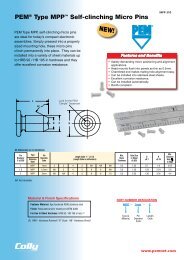
FASTENERS <strong>FOR</strong> USE <strong>WITH</strong> <strong>PC</strong> <strong>BOARDS</strong><br />
No matter how sophisticated or advanced, electronic components must be attached reliably and securely if<br />
they are to deliver optimum performance. We offer several fastener products for use with <strong>PC</strong> boards to satisfy<br />
component-to-board, board-to-board, and board-to-chassis attachment needs.<br />
Concerns about potential damage to <strong>PC</strong> boards due to improper secondary installation operations have prompted<br />
our latest innovative solution, ReelFast ® surface mount fasteners. These fasteners mount on <strong>PC</strong> boards in<br />
the same manner and at the same time as other surface mount components prior to the automated reflow solder<br />
process. The fasteners simply become another board component. The fasteners are provided on tape and reel<br />
compatible with existing SMT automated installation equipment. The benefits of using ReelFast ® SMT fasteners<br />
are: faster assembly; reduced scrap; reduced handling; and reduced risk of board damage that may occur when<br />
fasteners are improperly installed with off-line equipment.<br />
Broaching fasteners can also offer practical alternatives to “loose” hardware. They install permanently in all<br />
types of <strong>PC</strong> boards, as well as aluminum, acrylic, casting and polycarbonate components. A broaching fastener<br />
is a knurled-shank fastening device that can be pressed into a hole to provide a strong threaded or unthreaded<br />
attachment point in non-metal materials. Specially formed axial grooves around the shank of the fastener “broach”<br />
or cut into the material, creating a firm, interference-type fit resistant to rotation. Broach/flare-mount standoffs<br />
(Type KFB3) offer greater pullout performance.<br />
NUTS AND SPACERS/STANDOFFS<br />
Type SMTSO - ReelFast ® surface mount nuts and standoffs are available threaded and unthreaded. SEE PAGE 4<br />
Type KF2 and KFS2 - Broaching nuts, internally threaded for mounting on <strong>PC</strong> boards. SEE PAGE 5<br />
Type KFE and KFSE - Broaching standoffs, threaded or unthreaded for stacking or spacing. SEE PAGE 6<br />
Type KFB3 - Broach/flare-mount standoffs with greater pullout performance. SEE PAGE 6<br />
Type KSSB - Broaching, SNAP-TOP ® standoffs feature a spring action to hold <strong>PC</strong> board securely without screws or threaded<br />
hardware. SEE PAGE 7<br />
STUDS<br />
Type KFH - Threaded broaching studs for use as solderable connectors or as permanently mounted studs on <strong>PC</strong> boards. SEE<br />
PAGE 8<br />
CAPTIVE PANEL SCREWS<br />
ReelFast ® surface mount captive panel screws. SEE PAGE 9<br />
Type PFK - Broaching panel fastener assemblies for mounting on <strong>PC</strong> boards. SEE PAGE 10<br />
RIGHT ANGLE FASTENERS<br />
Type SMTRA - ReelFast ® R’ANGLE ® surface mount fasteners provide strong re-usable threads at right angles to <strong>PC</strong> boards. SEE<br />
PAGE 11<br />
SHEET JOINING FASTENERS<br />
Type SFK - SpotFast ® clinch/broach mount fasteners for joining metal to <strong>PC</strong>B/plastic panels. SEE PAGE 12<br />
Material and Finish Specifications. SEE PAGE 13<br />
Installation. SEE PAGES 14-15<br />
Performance Data. SEE PAGES 16-17<br />
Other fasteners for use with <strong>PC</strong> boards. SEE PAGE 18<br />
QUICK REFERENCE CHART<br />
PEM<br />
Fastener Page<br />
Type No.<br />
FASTENERS <strong>FOR</strong> USE <strong>WITH</strong> <strong>PC</strong> <strong>BOARDS</strong><br />
Mounting Types<br />
Primary Use<br />
Broach/ Clinch/ Right<br />
Broach Flare Surface Broach Spacer/ Snap Captive Color Angle Sheet<br />
Mount Mount Mount Mount Nut Standoff Attachment Stud Screw Coding Attachment Joining<br />
Broaching and broach/flare types are designed for unplated thru-hole applications. If used in plated thru-hole<br />
applications, the stresses involved can damage the plating, push out the plating entirely, or break any traces<br />
inside the board that might be connected to the plated hole. Increasing the mounting hole size +.005” to +.008”<br />
/+0.13 to +0.2 may relieve these conditions. In non-plated thru-holes this will also help when delamination,<br />
measeling or crazing is evident after installation. When none of the above can be tolerated, we recommend<br />
type SMTSO (solder-mount) type fasteners.<br />
General recommendations for “Keep Out” areas are the same as our “Min. Distance Hole C/L to Edge”<br />
dimensions stated in the dimensional charts of our bulletin.<br />
K-2 PennEngineering • www.pemnet.com PennEngineering • www.pemnet.com K-3<br />
SMTSO<br />
Nut/Spacer/Standoff<br />
KF2/KFS2<br />
Nut<br />
KFE/KFSE<br />
Spacer/Standoff<br />
KFB3<br />
Standoff<br />
KSSB<br />
Standoff<br />
KFH<br />
Stud<br />
SMTPF<br />
Assembly<br />
PFK<br />
Captive Screw<br />
SMTRA<br />
Right Angle<br />
SFK<br />
Sheet Joining<br />
4 • • •<br />
5 • •<br />
6 • •<br />
6 • •<br />
7 • • •<br />
8 • •<br />
9 • • •<br />
10 • •<br />
11 • •<br />
12 • • •
TYPE SMTSO ReelFast ® SURFACE MOUNT STANDOFFS<br />
All dimensions are in millimeters.<br />
METRIC<br />
NUTS AND SPACERS/STANDOFFS NUTS AND SPACERS/STANDOFFS<br />
Packaged on 13” recyclable reels. Tape width is 24mm. Supplied with polyimide patch for vacuum pick up.<br />
Reels conform to EIA-481.<br />
E<br />
C<br />
A<br />
L<br />
Stencil Masking Examples<br />
Thread Thru Thread or Min. ØH Hole Size ØD<br />
Length Code “L” ±0.13<br />
Size x Hole Thru Hole Sheet A C E In Sheet Min. Solder<br />
(Length code in millimeters)<br />
Pitch +0.10 –0.08 Type Code Thickness Max. Max. ±0.13 +0.08 Pad<br />
m2 x 0.4 — SmTSO m2 2 3 4 6 8 10 1.53 1.53 3.6 5.56 3.73 6.2<br />
m2.5 x 0.45 — SmTSO m25 2 3 4 6 8 10 1.53 1.53 4.09 5.56 4.22 6.2<br />
m3 x 0.5 — SmTSO m3 2 3 4 6 8 10 1.53 1.53 4.09 5.56 4.22 6.2<br />
m3.5 x 0.6 — SmTSO m35 2 3 4 6 8 10 1.53 1.53 5.28 7.14 5.41 7.77<br />
m4 x 0.7 — SmTSO m4 2 3 4 6 8 10 1.53 1.53 6.22 8.74 6.35 9.37<br />
— 3.6 SmTSO 3.6 2 3 4 6 8 10 1.53 1.53 5.28 7.14 5.41 7.77<br />
— 4.2 SmTSO 4.2 2 3 4 6 8 10 1.53 1.53 6.22 8.74 6.35 9.37<br />
NUMBER OF PARTS PER REEL / PITCH (MM) <strong>FOR</strong> EACH SIZE<br />
Thread/Thru-Hole Length Code<br />
Size 2 3 4 6 8 10 12<br />
m2, m25, m3, m35, 3.6 1500 / 12 1000 / 12 900 / 12 650 / 12 375 / 16 300 / 16 —<br />
m4, 4.2 1100 / 16 800 / 16 675 / 16 500 / 16 375 / 16 300 / 16 —<br />
ØD<br />
ØH<br />
Solder<br />
Pad<br />
Plated through<br />
hole not required.<br />
PART NUMBER DESIGNATION<br />
SMTSO – M3 – 6 ET<br />
Type<br />
Thread or<br />
Thru Hole<br />
Code<br />
Length<br />
Code<br />
Finish<br />
Code<br />
TYPES KF2 AND KFS2 BROACHING NUTS<br />
All dimensions are in millimeters.<br />
K-4 PennEngineering • www.pemnet.com PennEngineering • www.pemnet.com K-5<br />
METRIC<br />
Thread<br />
Type<br />
Size x Thread<br />
Pitch<br />
Carbon Stainless Code<br />
Steel Steel<br />
PART NUMBER DESIGNATION<br />
KF2 – M3 – ET<br />
Type and Thread<br />
material Code<br />
KF = carbon steel<br />
KFS = stainless steel<br />
A<br />
(Shank)<br />
Max.<br />
Finish<br />
Code<br />
Min.<br />
Sheet<br />
Thickness<br />
Hole Size<br />
In Sheet<br />
+0.08<br />
C E T<br />
±0.08 ±0.13 ±0.13<br />
m2 x 0.4 KF2 KFS2 m2 1.53 1.53 3.73 4.19 5.56 1.5 4.2<br />
m2.5 x 0.45 KF2 KFS2 m2.5 1.53 1.53 4.22 4.68 5.56 1.5 4.4<br />
m3 x 0.5 KF2 KFS2 m3 1.53 1.53 4.22 4.68 5.56 1.5 4.4<br />
m4 x 0.7 KF2 KFS2 m4 1.53 1.53 6.4 6.86 8.74 2 6.4<br />
m5 x 0.8 KF2 KFS2 m5 1.53 1.53 6.9 7.37 9.53 3 7.1<br />
E<br />
C<br />
A T<br />
Min. Dist.<br />
HoleC/L<br />
To Edge
TYPES KFE AND KFSE BROACHING STANDOFFS<br />
All dimensions are in millimeters.<br />
METRIC METRIC<br />
Thru Type Thread<br />
A Min. Hole Size Min.<br />
Thread Hole or Thru<br />
Length “L” ±0.13 (Shank) Sheet In Sheet C E Dist.<br />
Size x +0.10 Carbon Stainless Hole (Length Code is in millimeters) Max. Thick- +0.08 ±0.08 ±0.13 HoleC/L<br />
Pitch –0.08 Steel Steel Code ness To Edge<br />
m3 x 0.5 (2) KFe KFSe m3 3 4 6 8 10 12 14 16 1.53 1.53 4.22 4.68 5.56 4.4<br />
(2) 3.6 KFe KFSe 3.6 3 4 6 8 10 12 14 16 1.53 1.53 5.41 5.87 7.14 5.5<br />
(2) 4.2 KFe KFSe 4.2 3 4 6 8 10 12 14 16 1.53 1.53 6.4 6.86 8.74 7.1<br />
“F” minimum Thread Length (Where Applicable) Full 9.5 ± 0.4<br />
TYPE KFB3 BROACH/FLARE-MOUNT STANDOFFS<br />
All dimensions are in millimeters.<br />
Hole Size Min.<br />
Thread Thread Length “L” ±0.13<br />
A in Sheet Dist.<br />
Size x Type Code (Shank) Sheet +0.13 B C E K P Hole C/L<br />
Pitch<br />
(Length Code is in millimeters)<br />
Max. Thickness –0.03 ±0.08 Max. ±0.13 ±0.08 ±0.25 To<br />
Edge<br />
m3 x 0.5 KFB3 m3 2 3 4 6 8 10 12 14 16 2.29 1.27-1.65 4.22 3.23 4.2 5.56 4.55 1 4.33<br />
m4 x 0.7 KFB3 m4 2 3 4 6 8 10 12 14 16 2.29 1.27-1.65 6.4 5.23 6.33 8.74 6.68 1 6.36<br />
“F” min. Thread Length<br />
(Where Applicable)<br />
PART NUMBER DESIGNATION<br />
KFE – M3 – 12 ET<br />
Type and<br />
material<br />
KFe = carbon steel<br />
KFSe = stainless steel<br />
Thread<br />
or Thru<br />
Hole<br />
Code<br />
Length<br />
Code<br />
PART NUMBER DESIGNATION<br />
KFB3 – M3 – 12 ET<br />
Type and<br />
material<br />
Full 9.5 ±0.4<br />
(1) Blind at shank end with .375” minimum thread length from head end.<br />
(2) Not applicable. NA - Not Available.<br />
NUTS AND SPACERS/STANDOFFS NUTS AND SPACERS/STANDOFFS<br />
Thread<br />
Code<br />
Length<br />
Code<br />
Finish<br />
Code<br />
Finish<br />
Code<br />
C<br />
E A L<br />
F<br />
K C B<br />
E A L<br />
P<br />
C<br />
A L<br />
F<br />
TYPE KSSB BROACHING SNAP-TOP ® STANDOFFS<br />
All dimensions are in millimeters.<br />
K-6 PennEngineering • www.pemnet.com PennEngineering • www.pemnet.com K-7<br />
METRIC METRIC<br />
Type<br />
Top Board<br />
Mounting<br />
Hole<br />
Diameter<br />
Code<br />
Length “L” ±0.13<br />
(Length Code is in millimeters)<br />
B<br />
±0.13<br />
C<br />
±0.08<br />
H<br />
±0.13<br />
P<br />
±0.13<br />
T<br />
±0.13<br />
KSSB 4mm 8 10 12 14 16 18 20 22 25 4.8 5.74 6.35 3.58 0.51<br />
TYPE KSSB APPLICATION DATA<br />
All dimensions are in millimeters.<br />
PART NUMBER DESIGNATION<br />
KSSB – 4mm – 12<br />
Type and<br />
material<br />
Top Board<br />
mounting<br />
Hole<br />
Diameter<br />
Code<br />
Mounting Hole A<br />
Mounting Hole B<br />
Length<br />
Code<br />
PANEL 1 (Bottom) PANEL 2 (Top)<br />
Type Bottom Mounting Edge Location Top Mounting Edge<br />
Hole B Material Hardness Thickness Distance Tolerance Hole A Material Hardness Thickness Distance<br />
+0.08 Max. Min. C 1 Min. Max. +0.08 Max. Range C 2 Min.<br />
KSSB 5.4 <strong>PC</strong> Board HRB 65 1.25 5.6 ±0.13 4 <strong>PC</strong> Board No Limit 1 - 1.8 2.5<br />
or metal<br />
H<br />
Location<br />
Tolerance<br />
B<br />
Edge<br />
C 2<br />
Edge<br />
C 1<br />
P<br />
L<br />
PANEL 2 (TOP)<br />
PANEL 1 (BOTTOM)<br />
C<br />
T
TYPE KFH BROACHING STUDS<br />
All dimensions are in millimeters.<br />
METRIC<br />
PART NUMBER DESIGNATION<br />
KFH – M3 – 8 ET<br />
Type and<br />
material<br />
Thread<br />
Code<br />
Length<br />
Code<br />
STUDS<br />
Finish<br />
Code<br />
H<br />
L<br />
S T<br />
Hole Max. Min.<br />
Thread Thread Length “L” ±0.25<br />
A Min. Size in Hole Dist.<br />
Size x Type Code (Length Code is in millimeters)<br />
(Shank) Sheet Sheet Size in H S T HoleC/L<br />
Pitch Max. Thickness +0.08 Attached ±0.25 Max. ±0.13 To<br />
Parts Edge<br />
m3 x 0.5 KFH m3 6 8 10 12 15 18 1.65 1.53 3 3.7 4.58 2.3 0.51 3.8<br />
m4 x 0.7 KFH m4 6 8 10 12 15 18 1.65 1.53 4.2 4.8 5.74 2.3 0.51 5.1<br />
m5 x 0.8 KFH m5 6 8 10 12 15 18 1.65 1.53 5 5.8 6.6 2.3 0.51 5.3<br />
A<br />
ReelFast ® SURFACE MOUNT CAPTIVE PANEL SCREWS<br />
All dimensions are in millimeters.<br />
Available with six-lobe<br />
recess on special order.<br />
PART NUMBER DESIGNATION<br />
<strong>FOR</strong> SCREW<br />
PSHP – M3 – 0 L 001<br />
PART NUMBER DESIGNATION<br />
<strong>FOR</strong> RETAINER<br />
SMTPR – 6 – 1 ET<br />
Stencil Masking Examples<br />
K-8 PennEngineering • www.pemnet.com PennEngineering • www.pemnet.com K-9<br />
METRIC<br />
Spring action of<br />
plastic “fingers”<br />
holds screw<br />
in retracted<br />
position.<br />
When Assembled<br />
P<br />
PSHP<br />
SMTPR<br />
T 2<br />
Patented.<br />
Screw Part Number Assembly Dimensions Screw Dimensions Retainer Dimensions<br />
Thread Screw Retainer Total A Min.<br />
Size x Thread Length Part G P T 1 T 2 Radial C 1 E 1 L T (Shank) Sheet B C E R<br />
Pitch Type Code Code Number ± 0.64 ± 0.64 Nom. Nom. Float ±0.25 ±0.25 ±0.38 Nom. Max. Thick. ±0.08 Max. Nom. ±0.13<br />
0<br />
4.78 0<br />
m3 x 0.5 PSHP m3 SmTPR-6-1 12.14 16.41 .38 11.18 13.77 12.95 16.84 1.53 1.53 4.24 6.33 9.53 8.26<br />
1 6.3 .66 14.48 18.36<br />
m3.5 x 0.6 PSHP m3.5<br />
<strong>PC</strong> Board<br />
COLOR CAPABILITIES <strong>FOR</strong> TYPE PSHP SCREW<br />
The colors shown here (codes #002 thru #007) are non-stocked<br />
standards and available on special order. Since actual cap colors may<br />
vary slightly from those shown here, we recommend that you request<br />
samples for color verification. If you require a custom color or you need<br />
a “color matched” cap, please contact us.<br />
Std. Black #001 Red #002 Orange #003 Yellow #004<br />
Green #005 Blue #006 Violet #007<br />
Non-flammable UL 94-V0 plastic caps are available on special order.<br />
CAPTIVE PANEL SCREWS<br />
T 1<br />
G<br />
0<br />
4.78 0<br />
SmTPR-6-1 12.14 16.41 .51 11.18 13.77 12.95 16.84 1.53 1.53 4.24 6.33 9.53 8.26<br />
1 6.3 .66 14.48 18.36<br />
Type<br />
Type<br />
A<br />
E<br />
Thread<br />
Code<br />
Retainer<br />
Size<br />
RETAINER - Packaged on 13” recyclable reels of 465 pieces.<br />
Tape width is 24mm. Supplied with Kapton ® patch for vacuum<br />
pick up. Reels conform to EIA-481.<br />
SCREW - Packaged in bags. Retainers and screws are sold<br />
separately.<br />
Four dimples on<br />
head designate<br />
metric thread.<br />
Metal Phillips Recess<br />
M3 = #1<br />
M3.5 = #2<br />
Length<br />
Code<br />
R<br />
Cap<br />
Style<br />
(Lobed)<br />
Shank<br />
Code<br />
10.06mm<br />
Min.<br />
Color<br />
Code<br />
(Standard<br />
Black)<br />
Finish<br />
Code<br />
C 1<br />
C B E 1<br />
L<br />
T<br />
Solder<br />
Pad<br />
Plated through<br />
hole not required.<br />
6.35mm +0.08
TYPE PFK BROACHING<br />
CAPTIVE PANEL SCREWS<br />
All dimensions are in millimeters.<br />
METRIC<br />
PART NUMBER DESIGNATION<br />
PFK – M3 – 62<br />
Type and<br />
material<br />
Thread<br />
Code<br />
CAPTIVE PANEL SCREWS RIGHT ANGLE FASTENERS<br />
Screw<br />
Length<br />
Code<br />
Diagonal knurl<br />
identifies metric<br />
thread sizes<br />
Thread Thread Screw A Min. Hole Size C E G H P T 1 T 2 Min. Dist.<br />
Size x Type Code Length (Shank) Sheet In Sheet ±0.08 +0.4 ±0.4 ±0.13 Nom. Max. Nom. Hole CL<br />
Pitch Code Max. Thickness +0.08 –0.13 (2) To Edge<br />
40 6.4 0<br />
m3 x 0.5 PFK m3 62 1.53 1.53 6.75 7.19 7.87 9.5 1.83 3.2 9.15 13.72 5.1<br />
84 12.7 6.4<br />
*Retaining rings are plastic with normal 120°C temperature limit. (2) Screw may protrude 0.13mm beyond nominal dimensions.<br />
T 2<br />
P<br />
C<br />
A<br />
T 1<br />
G<br />
E<br />
H<br />
Look for the<br />
PEM trademark<br />
- a blue plastic<br />
retaining ring.*<br />
ReelFast ® SURFACE MOUNT R’ANGLE ® FASTENERS<br />
K-10 PennEngineering • www.pemnet.com PennEngineering • www.pemnet.com K-11<br />
Patented.<br />
All dimensions are in millimeters.<br />
METRIC METRIC<br />
Min. Hole<br />
Thread Thread Height Length Length Sheet Size A B C D Height G J K N P S P T<br />
Size x Type Code Code Code L Thick- In Sheet ±0.15 ±0.15 ±0.15 ±0.15 F ±0.15 Nom. Nom. Max. Max. ±0.08 Nom.<br />
Pitch ±0.13 ness +0.08 ±0.15<br />
m2 x 0.4 SmTRA m2 6 5 5 1 1.35 5.5 1 1.5 3.5 6 8.4 0.5 0.75 1.22 1 4 2.65<br />
m2.5 x 0.45 SmTRA m25 6 5 5 1 1.35 5.5 1 1.5 3.5 6 8.4 0.5 0.75 1.22 1 4 2.65<br />
m3 x 0.5 SmTRA m3 7 5 5 1 1.35 6.35 1.25 1.65 4 7 9.75 0.5 0.75 1.22 1 4.75 3.2<br />
m4 x 0.7 SmTRA m4 9 7 7 1 1.35 9.53 1.25 1.65 6.35 9 13.1 0.5 0.75 1.22 1 7.9 4.8<br />
Thread Pad Width Pad Length Hole Spacing Hole Size<br />
Code P A P L S H In Sheet<br />
Min. Min. ±0.05 +0.08<br />
m2 6.62 4.57 4 1.35<br />
m25 6.62 4.57 4 1.35<br />
m3 7.47 4.57 4.75 1.35<br />
m4 10.65 6.57 7.9 1.35<br />
PART NUMBER DESIGNATION<br />
SMTRA – M3 – 7 – 5 ET<br />
Type<br />
Thread<br />
Code<br />
Height<br />
Code<br />
Length<br />
Code<br />
Finish<br />
Code<br />
P A<br />
Solder Pad<br />
P<br />
Can be flush<br />
to edge. Plated<br />
through hole not<br />
required.<br />
S H<br />
G<br />
J<br />
Stencil Masking Examples<br />
P L<br />
K<br />
N<br />
Grooves<br />
identify<br />
unified<br />
thread<br />
F<br />
T<br />
D<br />
S P<br />
A<br />
Part Parts Pitch Tape Width<br />
Number Per Reel (mm) (mm)<br />
SmTRAm2-6-5 375 16 24<br />
SmTRAm25-6-5 375 16 24<br />
SmTRAm3-7-5 300 16 24<br />
SmTRAm4-9-7 200 20 32<br />
B<br />
L<br />
C
TYPE SFK SpotFast ® CLINCH/BROACH MOUNT FASTENERS<br />
Patented.<br />
Metal<br />
Plastic<br />
(1) Fastener will provide flush application at minimum sheet thickness.<br />
Can be used as a single flush-mounted<br />
pivot point. For more information, please<br />
contact our Applications Engineering<br />
Department.<br />
SHEET JOINING FASTENERS<br />
L<br />
Panel 1 Panel 2<br />
Type Thickness Min. Dist<br />
and Thickness Thickness Mounting Hole Min. Mounting Hole C 1 C 2 E L Hole C/L<br />
Size Code ±0.08mm +0.08mm (1) +0.08mm Max. ±0.08mm Max. Max. To Edge<br />
C 2<br />
mm mm mm mm mm mm mm mm mm<br />
SFK-3 0.8 0.8 3 1.6 2.5 2.98 2.9 3.53 2.31 3<br />
SFK-3 1.0 1 3 1.6 2.5 2.98 2.9 3.76 2.51 3<br />
SFK-3 1.2 1.2 3 1.6 2.5 2.98 2.9 3.76 2.72 3<br />
SFK-3 1.6 1.6 3 1.6 2.5 2.98 2.9 3.76 3.12 3<br />
SFK-5 0.8 0.8 5 1.6 4.5 4.98 4.9 5.56 2.31 5.1<br />
SFK-5 1.0 1 5 1.6 4.5 4.98 4.9 5.56 2.51 5.1<br />
SFK-5 1.2 1.2 5 1.6 4.5 4.98 4.9 5.56 2.72 5.1<br />
SFK-5 1.6 1.6 5 1.6 4.5 4.98 4.9 5.56 3.12 5.1<br />
C 1<br />
Panel 1<br />
Panel 2<br />
E<br />
Metal<br />
<strong>PC</strong>B/plastic<br />
Type SFK joining metal to <strong>PC</strong>B/plastic.<br />
PART NUMBER DESIGNATION<br />
SFK – 3 – 0.8 – ZI<br />
Type<br />
Panel 1<br />
mounting<br />
Hole Code<br />
Thickness<br />
Code<br />
Finish<br />
Code<br />
MATERIAL AND FINISH SPECIFICATIONS<br />
Threads (1) Fastener Materials Standard Finishes Optional Finishes For Use in Sheet Hardness: (3)<br />
Electro-Plated Electro-Plated<br />
Bright Matte Tin ASTM<br />
Internal, External, Tin ASTM B 545, Class A<br />
ASME ASME 300 Passivated B 545, Class B With Clear<br />
B1.1 2B/ B1.1 2A/ Series CDA-510 and/or With Clear Preservative HRB 70 / HRB 65 / HRB 60 / HRB 55 / HRB 50 /<br />
ASME ASME Carbon Stainless Phosphor CDA-353 7075-T6 Tested Per Preservative No Coating, Black HB 125 HB 116 HB 107 HB 83 HB 82 <strong>PC</strong><br />
Type B1.13M 6H B1.13M 6g Steel Steel Bronze Brass Aluminum ASTM A380 Coating Finish Annealed Nitride or Less or Less or Less or Less or Less Board<br />
KF2 • • • • • •<br />
KFS2 • • • • •<br />
KFe • • • • • •<br />
KFSE • • • • •<br />
KFB3 • • • • • •<br />
KSSB • • • •<br />
KFH • • • • • •<br />
PFK • • • • • •<br />
Part Number Codes For Finishes None eT X DT BN<br />
For Use In<br />
Threads (1) Fastener Materials Standard Finishes (2) Optional Finish (2) Sheet Hardness: (3)<br />
Electro-Plated Electro-Plated<br />
Bright Matte Tin ASTM<br />
Internal, External, ABS Tin ASTM Bright B 545, Class A<br />
ASME ASME Temp. B 545, Class A Nickel With Clear<br />
B1.1 2B/ B1.1 2A/ Limit Zinc Plated With Clear Over Preservative HRB 80 /<br />
ASME ASME Carbon 200˚ F Zinc 5µm, Preservative Copper Coating, HB 150 <strong>PC</strong><br />
Type B1.13M 6H B1.13M 6g Steel 93˚ C Diecast Colorless Coating Flash Annealed or less Board<br />
SMTSO • • • • •<br />
SMTRA • • • (4) • (4) •<br />
SMTPR • • • •<br />
(1) For plated studs, Class 2A/6g, the maximum major and pitch diameter, after plating, may equal basic sizes and can be gauged to Class 3A/6h,<br />
per ASME B1.1 (see notes at end of table C-1) and ASME B1.13M, Section 8, Paragraph 8.2.<br />
(2) See PEM Technical Support section of our web site for related plating standards and specifications.<br />
(3) HRB - Hardness Rockwell “B” Scale. HB - Hardness Brinell.<br />
(4) Optimal solderability life noted on packaging.<br />
K-12 PennEngineering • www.pemnet.com PennEngineering • www.pemnet.com K-13<br />
PSHP<br />
Cap •<br />
Screw • • •<br />
SFK • • • •<br />
Part Number Codes For Finishes ZI eT CN DT
For Types KF2, KFS2, KFE, KFSE, and PFK<br />
ANVIL<br />
PUNCH<br />
D<br />
Type KSSB<br />
L +<br />
5.1 mm Min.<br />
ANVIL<br />
INSTALLATION<br />
1. Prepare properly sized mounting hole in board.<br />
G<br />
2. Place fastener into the anvil hole and place the mounting<br />
PUNCH<br />
hole over the shank of the fastener as shown in drawing.<br />
3. With punch and anvil surfaces parallel, apply squeezing<br />
force until shoulder contacts the board. ANVIL<br />
ANVIL<br />
Part D G<br />
Number +0.08mm Min.<br />
PFK-m3-40 4.5mm 6.4mm<br />
PFK-m3-62 4.5mm 9.5mm<br />
PFK-m3-84 4.5mm 12.7mm<br />
For Type KFB3 (1)<br />
PUNCH<br />
D<br />
Type KFH<br />
L Min.<br />
(1) PennEngineering manufactures and stocks the installation tooling for the KFB3.<br />
Types KF2, KFS2,<br />
KFE, KFSE<br />
For Types KSSB and KFH<br />
Type PFK<br />
1. Prepare properly sized mounting hole in board.<br />
2. Place fastener into mounting hole as shown in<br />
drawing.<br />
3. With punch and anvil surfaces parallel, apply<br />
squeezing force until head contacts the board.<br />
1. Punch or drill properly sized round mounting hole in board.<br />
2. Place fastener into the anvil hole and place the mounting hole over the shank of the fastener<br />
as shown in diagram to the left.<br />
3. Using a punch flaring tool and a recessed anvil, apply squeezing force until the shoulder of<br />
the fastener contacts the board. As the fastener seats itself in the proper position, the punch<br />
tool will flare the extended portion of the shank outward to complete the installation. The<br />
combination of broaching and flaring provides high pushout performance.<br />
Thread Length<br />
Anvil<br />
Punch<br />
Code Code (Flaring Tool)<br />
m3 -2 975201213300<br />
m3 -3 to -6 975200846300<br />
m3 -8 to -10 975200847300 975201231400<br />
m3 -12 to -14 975201222300<br />
m3 -14 to -16 975200848300<br />
m4 -2 975201216300<br />
m4 -3 to -6 975201217300<br />
m4 -8 to -10 975201218300 975201221400<br />
m4 -12 to -14 975201220300<br />
m4 -14 to -16 975201219300<br />
Part D<br />
Number +0.08mm<br />
KFH-m3-L 3.1mm<br />
KFH-m4-L 4.1mm<br />
KFH-m5-L 5.1mm<br />
KSSB-4mm-L 5.49mm<br />
PUNCH<br />
D<br />
BE<strong>FOR</strong>E<br />
AFTER<br />
ANVIL<br />
Type KFB3<br />
PUNCH<br />
For Type SFK<br />
INSTALLATION<br />
Step 1. Prepare properly sized mounting hole in both panels.<br />
Step 2. Using only Panel 1, with the punch and anvil surfaces parallel,<br />
apply squeezing force until the fastener is flush with the top of<br />
Panel 1.<br />
Step 3. Place Panel 2 over fastener and apply squeezing force.<br />
ANVIL DIMENSIONS<br />
Size<br />
C<br />
±0.13 Punch Anvil<br />
(mm) Part No. Part No.*<br />
SFK-3 3.05 975200048 970200229300<br />
SFK-5 5.05 975200048 970200020300<br />
* Part number for anvil used in Step 2<br />
Panel 1 Metal<br />
K-14 PennEngineering • www.pemnet.com PennEngineering • www.pemnet.com K-15<br />
Punch<br />
NOTE: Fastener can be installed in both sheets at once when metal panel is adequately soft<br />
compared to the non-metal panel. E-mail techsupport@pemnet.com for more information.<br />
For SMT Nuts and Standoffs<br />
Solder paste applied<br />
to pad on <strong>PC</strong>B.<br />
Polymide patch applied here for<br />
vacuum pick up.<br />
Solder fastener in place<br />
using standard surface<br />
mount techniques.<br />
For SMT Captive Panel Screws<br />
Solder paste applied to<br />
pad on <strong>PC</strong>B.<br />
Polymide patch applied<br />
here for vacuum pick up.<br />
Solder fastener in place<br />
using standard surface<br />
mount techniques.<br />
Anvil<br />
C<br />
Step 2<br />
For SMT R’ANGLE ® Fasteners<br />
Solder paste applied<br />
to pad on <strong>PC</strong>B.<br />
Flat top for vacuum pick up.<br />
Solder fastener in place<br />
using standard surface<br />
mount techniques.<br />
Punch<br />
Panel 2 <strong>PC</strong>B/plastic<br />
Panel 1 Metal<br />
Anvil<br />
Screw snapped in place.<br />
Step 3<br />
Undercut to accept<br />
solder fillet and<br />
permit flush to edge<br />
installation.
METRIC METRIC<br />
Type<br />
PER<strong>FOR</strong>MANCE DATA (1) PER<strong>FOR</strong>MANCE DATA (1)<br />
ReelFast ® SMT product performance is dependent upon application variables. We will be happy to provide samples for you<br />
to install. If required, we can also test your installed hardware and provide you with specific performance data.<br />
TYPES KF2/KFS2, KFE/KFSE, KFB3, KFH, AND PFK BROACHING AND BROACH/FLARE MOUNT FASTENERS<br />
Thread Max. Nut Test Sheet Thickness Pushout<br />
Tightening Torque &<br />
Installation<br />
Code<br />
(N)<br />
(N•m) Test Sheet Material<br />
(kN)<br />
(2)<br />
(1) The values reported are averages when all installation specifications and procedures are followed. Variations in mounting hole size,<br />
sheet material, and installation procedure will affect this data. Performance testing of this product in your application is recommended.<br />
We will be happy to provide samples for this purpose or perform the installation for you.<br />
(2) These are typical values for parts installed in drilled mounting holes. Punched mounting holes yield values approximately 15% less.<br />
(3) Not applicable.<br />
(4) See Application Data drawing on page K-7.<br />
(5) 1 Mil Cu, .5 Mil Sn/Pb plated thru-hole.<br />
Panel 1 (1.5 mm FR-4 Fiberglass) (4) Panel 2 (Removable) (4)<br />
Torque-out<br />
(N•m)<br />
KF2 m3 (3) 1.5 mm FR-4 Fiberglass 2.2 290 1.7<br />
KFS2<br />
KFe m4 (3) 1.5 mm FR-4 Fiberglass 2.2 420 3.4<br />
KFSe m5 (3) 1.5 mm FR-4 Fiberglass 2.9 440 4.5<br />
KFB3<br />
m3<br />
m4<br />
(3)<br />
(3)<br />
1.5 mm FR-4 Fiberglass<br />
1.5 mm FR-4 Fiberglass<br />
4.4<br />
6<br />
560<br />
680<br />
2.03<br />
3.2<br />
m3 0.45 1.5 mm FR-4 Fiberglass 1.8 285 0.79<br />
KFH m4 1.6 1.5 mm FR-4 Fiberglass 1.8 355 1.8<br />
m5 2.1 1.5 mm FR-4 Fiberglass 1.8 400 1.92<br />
PFK m3 (3) 1.5 mm FR-4 Fiberglass 1.1 245 (3)<br />
TYPE KSSB BROACHING SNAP-TOP ® STANDOFFS<br />
Type Installation Pushout Max. First On Min. First Off Min. 15th Off<br />
(kN) (N) Force (N) Force (N) Force (N)<br />
KSSB 2.2 484 57.7 13.3 4.4<br />
PEMSERTER ® PRESSES<br />
For best results we recommend using a PEMSERTER ® press for installation<br />
of PEM broaching fasteners. For more information on our line of presses call<br />
1-800-523-5321 or check our web site.<br />
TYPE SFK SpotFast ® CLINCH/BROACH MOUNT FASTENERS<br />
Installation into Panel 1 Installation into Panel 2<br />
Pushout of Panel 2 (3)<br />
Type and Thickness Cold-rolled Steel FR-4 Fiberglass<br />
Size Code<br />
kN kN N<br />
SFK-3 0.8 6.2 1.8 200<br />
SFK-3 1.0 8 1.8 200<br />
SFK-3 1.2 8.9 1.8 200<br />
SFK-3 1.6 10.2 1.8 200<br />
SFK-5 0.8 11.1 1.8 400<br />
SFK-5 1.0 13.5 1.8 400<br />
SFK-5 1.2 15.6 1.8 400<br />
SFK-5 1.6 17.8 1.8 400<br />
(1) The values reported are averages when all installation specifications and procedures are followed. Variations in mounting hole size,<br />
sheet material, and installation procedure will affect this data. Performance testing of this product in your application is recommended.<br />
We will be happy to provide samples for this purpose or perform the installation for you.<br />
(2) In most applications, pullout strength of the SFK fastener in Panel 1 exceeds pushout strength of Panel 2.<br />
K-16 PennEngineering • www.pemnet.com PennEngineering • www.pemnet.com K-17
OTHER FASTENERS <strong>FOR</strong> CONSIDERATION TO USE <strong>WITH</strong> <strong>PC</strong> <strong>BOARDS</strong> PEM ® TRADEMARKS<br />
TYPE PF11MW FLOATING CAPTIVE PANEL SCREWS<br />
(See PEM ® Bulletin PF)<br />
Unique flare mount feature allow fasteners to “float” in mounting hole.<br />
• Compensates for mating thread misalignment.<br />
• Installs into any panel material.<br />
• Appropriate for close center-line-to-edge applications.<br />
• Color coded knobs available.<br />
TYPE PF11MF FLARE-MOUNTED CAPTIVE PANEL SCREWS<br />
(See PEM ® Bulletin PF)<br />
• Appropriate for close centerline-to-edge applications.<br />
• Doesn’t require high installation force.<br />
• Installs into any panel material.<br />
• Installs flush on back side of panel.<br />
• Color coded knobs available.<br />
TYPE SOAG AND SOSG GROUNDING STANDOFFS<br />
(See PEM ® Bulletin SO)<br />
• Designed for clinching into steel or aluminum chassis.<br />
• “Gripping teeth” on opposite side of standoff firmly contact mating <strong>PC</strong> Board.<br />
TYPE SKC KEYHOLE ® STANDOFFS<br />
(See PEM ® Bulletin SK)<br />
• Clinch feature mounts fastener permanently into metal sheet.<br />
• Allows for quick attachement and detachment of <strong>PC</strong> Board.<br />
• Head is flush or sub-flush in metal sheet.<br />
• Makes horizontal or vertical component mounting possible.<br />
TYPE SSA, SSC, AND SSS SNAP-TOP ® STANDOFFS<br />
(See PEM ® Bulletin SSA)<br />
• Spring action holds <strong>PC</strong> Boards and subassemblies securely, while<br />
allowing for quick removal.<br />
• Screws and other threaded hardware are eliminated.<br />
Can install<br />
into <strong>PC</strong><br />
Board,<br />
plastic<br />
or metal<br />
Can install<br />
into <strong>PC</strong><br />
Board,<br />
plastic<br />
or metal<br />
<strong>PC</strong> Board<br />
or plastic<br />
Metal<br />
<strong>PC</strong> Board<br />
or plastic<br />
Metal<br />
<strong>PC</strong> Board<br />
or plastic<br />
Metal<br />
For more information on these and other PEM products, visit our PEMNET Resource Center at www.pemnet.com<br />
To be sure that you are getting genuine PEM ® brand fasteners,<br />
look for our “dimple”, or “two groove” registered trademarks.<br />
K-18 PennEngineering • www.pemnet.com PennEngineering • www.pemnet.com K-19
RoHS compliance information can be found on our website.<br />
© 2010 PennEngineering.<br />
K-20<br />
FASTENERS <strong>FOR</strong> USE <strong>WITH</strong> <strong>PC</strong> <strong>BOARDS</strong><br />
Specifications subject to change without notice.<br />
Check our website for the most current version of this bulletin.