Design-in Guide for Xtreme drivers low wattage - Philips Lighting
Design-in Guide for Xtreme drivers low wattage - Philips Lighting
Design-in Guide for Xtreme drivers low wattage - Philips Lighting

You also want an ePaper? Increase the reach of your titles
YUMPU automatically turns print PDFs into web optimized ePapers that Google loves.
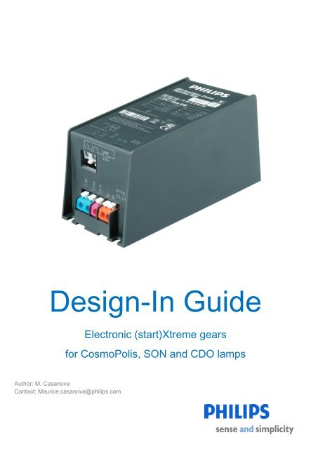
<strong>Design</strong>-In <strong>Guide</strong><br />
Electronic (start)<strong>Xtreme</strong> gears<br />
<strong>for</strong> CosmoPolis, SON and CDO lamps<br />
Author: M. Casanova<br />
Contact: Maurice.casanova@philips.com
Table of Contents<br />
General <strong>in</strong><strong>for</strong>mation ......................................................................................................................................................... 4<br />
1.1 Introduction ...................................................................................................................................................... 4<br />
1.2 Version management ....................................................................................................................................... 4<br />
1.3 Available <strong>Xtreme</strong> and start<strong>Xtreme</strong> gears ......................................................................................................... 5<br />
2 <strong>Design</strong><strong>in</strong>g-<strong>in</strong> Low Wattage <strong>Xtreme</strong> systems ................................................................................................................ 6<br />
2.1 Dimensions of <strong>Philips</strong> <strong>Xtreme</strong> and start<strong>Xtreme</strong> gears ..................................................................................... 6<br />
2.2 Ma<strong>in</strong>s properties .............................................................................................................................................. 8<br />
2.3 Ma<strong>in</strong>s behaviour ............................................................................................................................................... 9<br />
2.4 Other ma<strong>in</strong>s properties .................................................................................................................................. 10<br />
2.5 Connections ................................................................................................................................................... 10<br />
2.6 Lamp connection............................................................................................................................................ 10<br />
3.1 Factors affect<strong>in</strong>g lifetime ................................................................................................................................ 11<br />
3.2 Def<strong>in</strong>itions ...................................................................................................................................................... 11<br />
3.3 Temperature ................................................................................................................................................... 11<br />
3.4 Tc temperature on Low Wattage <strong>Xtreme</strong> gear ............................................................................................... 11<br />
3.5 Recommendations <strong>for</strong> thermal design-<strong>in</strong> ....................................................................................................... 12<br />
3.6 Thermal guard ................................................................................................................................................ 12<br />
3.7 EMC recommendations ................................................................................................................................. 12<br />
3.8 Remote lamp operation ................................................................................................................................. 13<br />
3.9 Lightn<strong>in</strong>g strike protection .............................................................................................................................. 13<br />
4 Fus<strong>in</strong>g Low Wattage <strong>Xtreme</strong> gear .............................................................................................................................. 16<br />
5 Class I and Class II applications ................................................................................................................................. 17<br />
Class I .................................................................................................................................................................... 17<br />
Class II ................................................................................................................................................................... 17<br />
5.1 Compliance to Class I/ Class II with maximum per<strong>for</strong>mance on EMC .......................................................... 17<br />
6 Operat<strong>in</strong>g <strong>in</strong> abnormal conditions ............................................................................................................................... 18<br />
6.1 End-of-life behaviour of <strong>Philips</strong> <strong>Xtreme</strong> and start<strong>Xtreme</strong> systems ................................................................ 18<br />
2
End-of-life causes .................................................................................................................................................. 18<br />
6.2 End-of-lamp behaviour .................................................................................................................................. 18<br />
6.3 Lamp-gear comb<strong>in</strong>ation mismatch................................................................................................................. 19<br />
7. Dimm<strong>in</strong>g functionality of Low Wattage <strong>Xtreme</strong> .......................................................................................................... 20<br />
8 Disclaimer ................................................................................................................................................................... 26<br />
Appendix 1 ..................................................................................................................................................................... 28<br />
How to use DynaVision <strong>Xtreme</strong> gear with L<strong>in</strong>e Switch. ................................................................................................. 28<br />
1.1 Introduction .................................................................................................................................................... 28<br />
13-12-2010: Version 0.1 ............................................................................................................................................ 28<br />
Appendix 2 ..................................................................................................................................................................... 30<br />
How to switch from standard DynaVision gear to DynaVision <strong>Xtreme</strong> gear ................................................................. 30<br />
2.4 Mechanical outl<strong>in</strong>e .................................................................................................................................................. 30<br />
2.6 Benefits of <strong>Xtreme</strong> lamp driver ................................................................................................................................ 31<br />
2.7 For more <strong>in</strong><strong>for</strong>mation ............................................................................................................................................... 31<br />
Appendix 3 ..................................................................................................................................................................... 32<br />
DynaVision Dali <strong>Xtreme</strong> - Programmable Drivers ......................................................................................................... 32<br />
Appendix 4 ..................................................................................................................................................................... 37<br />
Overview of dimm<strong>in</strong>g HID system.................................................................................................................................. 37<br />
3
General <strong>in</strong><strong>for</strong>mation<br />
1.1 Introduction<br />
Thank you <strong>for</strong> choos<strong>in</strong>g <strong>Philips</strong> <strong>Xtreme</strong> and start<strong>Xtreme</strong> gears.<br />
<strong>Xtreme</strong> gears have been specially developed <strong>for</strong> outdoor applications with long lifetime and high reliability as the key<br />
specifications. The electronic driver is designed <strong>for</strong> lamp types CPO/CDO/SON and can there<strong>for</strong>e be used <strong>in</strong> a wide<br />
range of applications:<br />
Decorative floodlight<strong>in</strong>g of architecture, monuments, etc.<br />
Decorative light<strong>in</strong>g of (large) city centres and shopp<strong>in</strong>g areas.<br />
Major and m<strong>in</strong>or roads.<br />
The electronic gear converts AC ma<strong>in</strong>s voltage by means of an AC/AC converter <strong>in</strong>to a <strong>low</strong>-frequency square<br />
wave lamp current. The electronic gear provides means to ignite and control the lamp. Ma<strong>in</strong>s and lamp power is<br />
<strong>in</strong>dependent of fluctuations with<strong>in</strong> the per<strong>for</strong>mance ma<strong>in</strong>s voltage range. The electronic gear is compliant with all<br />
relevant lamp specifications. The product has been developed to be easily designed-<strong>in</strong> <strong>in</strong>to Class I and Class II<br />
fixtures.<br />
1.2 Version management<br />
V 0.3 F<strong>in</strong>al Version<br />
4
1.3 Available <strong>Xtreme</strong> and start<strong>Xtreme</strong> gears<br />
At the date of release of this document the fol<strong>low</strong><strong>in</strong>g gears <strong>in</strong>corporat<strong>in</strong>g <strong>Philips</strong> <strong>Xtreme</strong> technology are available:<br />
Product name<br />
<strong>Philips</strong> HID-PV Xt 45 /S COSMOPOLIS-TW<br />
<strong>Philips</strong> HID-PV Xt 60 /S COSMOPOLIS-TW<br />
<strong>Philips</strong> HID-PV Xt 90 /S COSMOPOLIS-TW<br />
<strong>Philips</strong> HID-PV Xt 140 /S COSMOPOLIS-TW<br />
<strong>Philips</strong> HID-DV LS6 60 /S COSMOPOLIS-TW<br />
<strong>Philips</strong> HID-DV LS6 90 /S COSMOPOLIS-TW<br />
<strong>Philips</strong> HID-DV LS6 140 /S COSMOPOLIS-TW<br />
<strong>Philips</strong> HID-DV LS8 60 /S COSMOPOLIS-TW<br />
<strong>Philips</strong> HID-DV LS8 90 /S COSMOPOLIS-TW<br />
<strong>Philips</strong> HID-DV LS8 140 /S COSMOPOLIS-TW<br />
<strong>Philips</strong> HID-DV LS10 60 /S COSMOPOLIS-TW<br />
<strong>Philips</strong> HID-DV LS10 90 /S COSMOPOLIS-TW<br />
<strong>Philips</strong> HID-DV LS10 140 /S COSMOPOLIS-TW<br />
<strong>Philips</strong> HID-PV sXt 45 /S COSMOPOLIS 208-277V<br />
<strong>Philips</strong> HID-PV sXt 60 /S COSMOPOLIS 208-277V<br />
<strong>Philips</strong> HID-PV sXt 90 /S COSMOPOLIS 208-277V<br />
<strong>Philips</strong> HID-PV sXt 140 /S COSMOPOLIS 208-277V<br />
<strong>Philips</strong> HID-DV sXt 60 COSMOPOLIS / 0-6-60%<br />
<strong>Philips</strong> HID-DV sXt 90 COSMOPOLIS / 0-6-60%<br />
<strong>Philips</strong> HID-DV sXt 140 COSMOPOLIS / 0-6-60%<br />
<strong>Philips</strong> HID-DV sXt 60 COSMOPOLIS / 2-6-60%<br />
<strong>Philips</strong> HID-DV sXt 90 COSMOPOLIS / 2-6-60%<br />
<strong>Philips</strong> HID-DV sXt 140 COSMOPOLIS / 2-6-60%<br />
<strong>Philips</strong> HID-DV DALI Xt 45 /S COSMOPOLIS 208-277V<br />
<strong>Philips</strong> HID-DV DALI Xt 60 /S COSMOPOLIS 208-277V<br />
<strong>Philips</strong> HID-DV DALI Xt 90 /S COSMOPOLIS 208-277V<br />
<strong>Philips</strong> HID-DV DALI Xt 140 /S COSMOPOLIS 208-277V<br />
<strong>Philips</strong> HID-DV DALI Xt 50 SON<br />
<strong>Philips</strong> HID-DV DALI Xt 70 SON<br />
<strong>Philips</strong> HID-DV DALI Xt 100 SON<br />
<strong>Philips</strong> HID-DV DALI Xt 150 SON<br />
<strong>Philips</strong> HID-DV DALI Xt 50 /S CDO 208-277V<br />
<strong>Philips</strong> HID-DV DALI Xt 70/S CDO 208-277V<br />
<strong>Philips</strong> HID-DV DALI Xt 100 /S CDO 208-277V<br />
<strong>Philips</strong> HID-DV DALI Xt 150 /S CDO 208-277V<br />
5
2 <strong>Design</strong><strong>in</strong>g-<strong>in</strong> Low Wattage <strong>Xtreme</strong> systems<br />
2.1 Dimensions of <strong>Philips</strong> <strong>Xtreme</strong> and start<strong>Xtreme</strong> gears<br />
Figure 1.<br />
All four screws are required <strong>for</strong> correct <strong>in</strong>stallation of the gear (<strong>for</strong> reasons of vibration/cool<strong>in</strong>g)<br />
Dimensions accord<strong>in</strong>g to Figure 1. For the fol<strong>low</strong><strong>in</strong>g products:<br />
A B C<br />
<strong>Philips</strong> HID-PV Xt 45 /S COSMOPOLIS-TW 135mm 65mm 65mm<br />
<strong>Philips</strong> HID-PV Xt 60 /S COSMOPOLIS-TW 135mm 65mm 65mm<br />
<strong>Philips</strong> HID-DV LS6,8,10 60 /S COSMOPOLIS-<br />
TW<br />
135mm 65mm 65mm<br />
6
Figure 2.<br />
All four screws are required <strong>for</strong> correct <strong>in</strong>stallation of the gear (<strong>for</strong> reasons of vibration/cool<strong>in</strong>g)<br />
Dimensions accord<strong>in</strong>g to Figure 2. For the fol<strong>low</strong><strong>in</strong>g products:<br />
A B C<br />
<strong>Philips</strong> HID-PV Xt 90 /S COSMOPOLIS-TW 150mm 65mm 65mm<br />
<strong>Philips</strong> HID-PV Xt 140 /S COSMOPOLIS-TW 150mm 65mm 65mm<br />
<strong>Philips</strong> HID-DV LS6,8,10 90 /S COSMOPOLIS-TW 150mm 65mm 65mm<br />
<strong>Philips</strong> HID-DV LS6,8,10 140 /S COSMOPOLIS-TW 150mm 65mm 65mm<br />
<strong>Philips</strong> HID-DV sXt …. 150mm 65mm 65mm<br />
<strong>Philips</strong> HID-DV DALI Xt …… 150mm 65mm 65mm<br />
7
2.2 Ma<strong>in</strong>s properties<br />
The new DynaVision gears have a wide operat<strong>in</strong>g voltage per<strong>for</strong>mance range (198-254V), With<strong>in</strong> this range the<br />
electronic gear provides an almost constant power output (± 3%). This is favourable <strong>for</strong> lamp life and energy<br />
consumption (no overpower situation possible).<br />
If the ma<strong>in</strong>s voltage falls be<strong>low</strong> this specified per<strong>for</strong>mance range of the gear (see gear specification), the gear<br />
operates the lamp at a <strong>low</strong>er power. If the ma<strong>in</strong>s voltage drops be<strong>low</strong> 160V or rises above 320V, the gear shuts<br />
down.<br />
In Figure 3, the lamp power supplied by the electronic gear is shown <strong>in</strong> green as a function of ma<strong>in</strong>s voltage.<br />
Figure 3<br />
Ma<strong>in</strong>s voltage range, Pma<strong>in</strong>s_MAX [W] @ Rsub_lamp with Pla = nom.<br />
208V – 277V<br />
Nom<strong>in</strong>al output power 45W 50W 60W 70W 90W 100W 140W 150W<br />
Nom<strong>in</strong>al <strong>in</strong>put power 51W 56W 67W 78W 98W 106W 153W 160W<br />
Table 1<br />
8
2.3 Ma<strong>in</strong>s behaviour<br />
The absolute ma<strong>in</strong>s voltage range is specified as shown be<strong>low</strong>. If the ma<strong>in</strong>s voltage is too <strong>low</strong>, the gear will dim the<br />
lamp to 50% power so as to protect it aga<strong>in</strong>st too high an <strong>in</strong>put current. If the ma<strong>in</strong>s voltage drops be<strong>low</strong> the<br />
m<strong>in</strong>imum, the gear will shut down the lamp.<br />
This behaviour is represented <strong>in</strong> Figure 4:<br />
Figure 4<br />
2.4 Inrush current<br />
Test conditions: Vma<strong>in</strong>s = 230V<br />
Un: 208V - 277V<br />
fn: 50Hz / 60Hz<br />
M<strong>in</strong> Max<br />
Per<strong>for</strong>mance <strong>in</strong>put voltage range (Vper<strong>for</strong>mance) 187V 305V<br />
Per<strong>for</strong>mance <strong>in</strong>put frequency range 47.5Hz 63Hz<br />
Operational/safety <strong>in</strong>put voltage range 160V 305V<br />
Operational/safety <strong>in</strong>put frequency range 45Hz 66Hz<br />
v_<strong>in</strong>put_<strong>low</strong>_OFF 150V<br />
v_<strong>in</strong>put_<strong>low</strong>_ON 172V See<br />
v_<strong>in</strong>put_high_ON 310V Figure 4<br />
v_<strong>in</strong>put_high_OFF 320V<br />
Per<strong>for</strong>mance ma<strong>in</strong>s frequency range 47.5Hz 63Hz<br />
Operational/safety ma<strong>in</strong>s voltage range 160V 264V<br />
Operational/safety ma<strong>in</strong>s frequency range 45Hz 66Hz<br />
Table 2<br />
fma<strong>in</strong>s = 50Hz<br />
Zma<strong>in</strong>s_nom= Rma<strong>in</strong>s_nom + Lma<strong>in</strong>s_nom<br />
Rma<strong>in</strong>s_nom= 0.4Ω<br />
Lma<strong>in</strong>s_nom= 0.8mH<br />
9
Inrush Current @ 230V 45W 50W 60W 70W 90W 100W 140W 150W<br />
Ima<strong>in</strong>s –peak 28A 28A 28A 28A 52A 52A 52A 52A<br />
Ima<strong>in</strong>s -pulse time (µs) 420µs 420µs 420µs 420µs 470µs 470µs 470µs 470µs<br />
"number " 11 11 11 11 5 5 5 5<br />
Table 3<br />
2.4 Other ma<strong>in</strong>s properties<br />
The earth leakage current will be smaller than 0.7mAp.<br />
<strong>Xtreme</strong> gear can withstand 320V <strong>for</strong> 48 hours, which <strong>in</strong> most cases is sufficient to survive a loose Neutral l<strong>in</strong>e.<br />
Such high ma<strong>in</strong>s voltages adversely affect gear lifetime.<br />
2.5 Connections<br />
Connectors are „push-<strong>in</strong> contacts‟ suitable <strong>for</strong> 0.5 to 2.5mm 2 solid or stranded wir<strong>in</strong>g. When us<strong>in</strong>g stranded wires<br />
the contacts should be pushed <strong>in</strong> us<strong>in</strong>g the release button. However, ferules are advised when stranded wire is<br />
used. The wire can be released by press<strong>in</strong>g the release button and pull<strong>in</strong>g the wire. The ma<strong>in</strong>s connections are L<br />
and N-<strong>in</strong>different. Lamp connections 1 and 2 are suitable <strong>for</strong> handl<strong>in</strong>g 4.4kV (symmetric) pulses. The strip length of<br />
all wires is 10 to 11mm.<br />
Connector colour Colour<br />
Lamp 1: Grey<br />
Lamp 2: Grey<br />
Ma<strong>in</strong>s <strong>in</strong>put (Neutral):** Black<br />
Ma<strong>in</strong>s <strong>in</strong>put (L<strong>in</strong>e):** White<br />
Dali ( + ) * Blue<br />
Dali ( - ) * Blue<br />
Functional earth P<strong>in</strong>k<br />
* Not present on sXt<br />
** Orange ma<strong>in</strong>s <strong>in</strong>put connector still used <strong>in</strong> Hid–PV Xt 45/60/90 and 140/S CPO<br />
Table 4<br />
2.6 Lamp connection<br />
The <strong>in</strong>terconnection between gear and lamp has to be designed to withstand the ignition voltage. For optimal surge<br />
protection this <strong>in</strong>terconnection has to withstand 8kV <strong>in</strong> respect of earth/fixture.<br />
DALI XT PV XT sXT<br />
10
3.1 Factors affect<strong>in</strong>g lifetime<br />
The temperature of the electronics is an important parameter <strong>for</strong> the system‟s lifetime and reliability. Dur<strong>in</strong>g the<br />
design stage everyth<strong>in</strong>g possible is done to keep the component temperature as <strong>low</strong> as possible. but the design of<br />
the fixture and its ability to guide the heat out of the fixture are very important. Lifetime is based on one switch<strong>in</strong>g<br />
cycle per day; if more switch<strong>in</strong>g cycles are used this will have a negative effect on the lifetime of the gear.<br />
3.2 Def<strong>in</strong>itions<br />
Gear temperature: temperature measured at the Tc po<strong>in</strong>t of the gear.<br />
Gear ambient temperature: temperature <strong>in</strong>side the fixture around the gear.<br />
Fixture ambient temperature: temperature outside the fixture.<br />
Figure 5<br />
3.3 Temperature<br />
The gear is designed to be cooled at the mount<strong>in</strong>g surface. There is no po<strong>in</strong>t <strong>in</strong> cool<strong>in</strong>g down the Tc po<strong>in</strong>t because<br />
this po<strong>in</strong>t is a temperature reference measurement po<strong>in</strong>t. The temperature measured at this po<strong>in</strong>t is only valid if the<br />
gear is mounted <strong>in</strong> the way that <strong>Philips</strong> designed it. If the gear has to be mounted <strong>in</strong> a different way to that<br />
described, the <strong>Philips</strong> representative should be contacted.<br />
3.4 Tc temperature on Low Wattage <strong>Xtreme</strong> gear<br />
Tc is specified at 80°C on the label of <strong>Xtreme</strong> gears. At this temperature the lifetime of 80,000 hours with 90%<br />
survivors is achieved. At 90°C the thermal protection will switch off the gear. The gear will start try<strong>in</strong>g to reignite the<br />
lamp when the gear cools down to 80°C.<br />
Example:<br />
If <strong>in</strong> the application the Tc po<strong>in</strong>t is 80ºC (=Tc at which the lifetime spec of 80,000 hours with 90% survivors is<br />
achieved <strong>for</strong> CosmoWhite (s)<strong>Xtreme</strong> gear), then operat<strong>in</strong>g or even stor<strong>in</strong>g the gear at temperatures above 80°C<br />
will shorten the lifetime of the product. We there<strong>for</strong>e strongly advise that all measures be taken to avoid this<br />
possibility.<br />
Gear temperature<br />
Gear ambient temperature<br />
Figure 6<br />
11
3.5 Recommendations <strong>for</strong> thermal design-<strong>in</strong><br />
Ensure good and direct thermal contact between the gear and the coldest po<strong>in</strong>t on the fixture. The Low<br />
Wattage <strong>Xtreme</strong> gear is designed to comply with all the requirements <strong>for</strong> Class 1 and Class 2 applications,<br />
so direct contact with the metal parts of the fixture are al<strong>low</strong>ed.<br />
The Low Wattage <strong>Xtreme</strong> gear conta<strong>in</strong>s heat-produc<strong>in</strong>g components <strong>in</strong> the <strong>low</strong>er part of the gear, so<br />
cool<strong>in</strong>g via the bottom is required <strong>for</strong> best results.<br />
Shield the heat emitted by the lamp and reflector. The best way of do<strong>in</strong>g this is by means of a two-chamber<br />
solution.<br />
In larger fixtures <strong>in</strong>ternal convection can be used <strong>for</strong> cool<strong>in</strong>g, or special measures can be taken to transport<br />
heat away from the gear by means of airf<strong>low</strong>.<br />
Note: If the Tc temperature limit is reached be<strong>for</strong>e the maximum ambient temperature mentioned on the label is<br />
reached, the temperature at the Tc po<strong>in</strong>t is the limit<strong>in</strong>g factor <strong>in</strong> the application.<br />
3.6 Thermal guard<br />
If the gear temperature exceeds the maximum Tcase, 92±2°C, the thermal protection mechanism will start to dim the<br />
lamp power. For the COSMOPOLIS the lamp power will be reduced to 60% (50% light) and <strong>for</strong> SON it will be<br />
reduced to 35% (20% light). The gear will be switched off immediately when Tcase reaches 95±2°C. If the<br />
temperature drops be<strong>low</strong> Tcase 92±2°C with<strong>in</strong> 25 m<strong>in</strong>utes, the gear will return to full light level.<br />
If the Tcase falls be<strong>low</strong> 80±2°C, the gear will return to the previous value. Ignition is possible from -30ºC upwards.<br />
At very <strong>low</strong> temperatures it may take slightly longer to ignite the lamp.<br />
CPO<br />
SON<br />
CDO<br />
{70% light}<br />
3.7 EMC recommendations<br />
{70% light}<br />
{50% light}<br />
{50% light}<br />
COSMOPOLIS, SON and CDO (s)<strong>Xtreme</strong> gears operate the lamp us<strong>in</strong>g a <strong>low</strong>-frequency square wave.<br />
When design<strong>in</strong>g-<strong>in</strong> the gear <strong>in</strong>to the fixture the guidel<strong>in</strong>es be<strong>low</strong> can be useful <strong>for</strong> optimis<strong>in</strong>g EMI per<strong>for</strong>mance.<br />
1 Keep the ma<strong>in</strong>s wires (L and N) close together.<br />
2 <strong>Guide</strong> the ma<strong>in</strong>s wires immediately away from the gear.<br />
3 Preferably do not guide the wires along or on top of the gear.<br />
4 Keep the lamp wires close together and as short as possible. Figure 7<br />
5 Do not put the lamp wires close to the ma<strong>in</strong>s wires.<br />
This is shown schematically <strong>in</strong> Figure 7.<br />
12
6 For optimal EMI behaviour the large metal parts on the fixture (e.g. bottom plate, etc.) must always be<br />
connected to the earth contact of the gear, irrespective of whether it is Class I or 2.<br />
Connection of the earth term<strong>in</strong>al to the metal parts of the fixture should be kept as short as possible.<br />
Note: It is recommended that an EMC filter should be used <strong>in</strong> order to provide sufficient design-<strong>in</strong> marg<strong>in</strong><br />
concern<strong>in</strong>g EMC per<strong>for</strong>mance <strong>in</strong> case a comb<strong>in</strong>ation of CDO 50W gear and a CDO 50W lamp is used.<br />
3.8 Remote lamp operation<br />
Remote operation is the term used <strong>for</strong> outdoor applications where the gear is not <strong>in</strong>corporated <strong>in</strong> the fixture, but,<br />
<strong>for</strong> <strong>in</strong>stance, <strong>in</strong> the pole.<br />
Two technical aspects determ<strong>in</strong>e whether a remote application is possible. First of all the ignition voltage peak is<br />
<strong>in</strong>fluenced by the cable properties. This means that the peak voltage is flattened by the cable capacity. Depend<strong>in</strong>g on<br />
the <strong>in</strong>sulation material, some part of the ignition energy may even be absorbed by the cable. In general the cable<br />
capacity has a major <strong>in</strong>fluence. (s)<strong>Xtreme</strong> gear is capable of driv<strong>in</strong>g a cable capacity of up to 1nF. For an average<br />
cable type with a capacity of 100 pF/m this means that remote lamp operation with 10 metres of lamp cable is<br />
feasible.<br />
A second po<strong>in</strong>t to be aware of is the stray capacitance of the lamp conductors to the environment. Composite or<br />
wooden poles have the advantage of hav<strong>in</strong>g a <strong>low</strong> spread<strong>in</strong>g capacity. Alum<strong>in</strong>ium or steel poles will pick up more<br />
noise from the lamp cables. This disturbance has to be redirected to the gear by a short connection from the metal<br />
pole to the functional earth term<strong>in</strong>al on the gear. For remote gear<strong>in</strong>g, screened lamp cables are not recommended.<br />
To reduce the EM radiation it is recommended that a cable should be used <strong>for</strong> remote gear<strong>in</strong>g <strong>in</strong>stead of two<br />
separate wires.<br />
Note: If pole-mounted, the gear should always be fitted with the connectors po<strong>in</strong>t<strong>in</strong>g down. This prevents moisture<br />
from enter<strong>in</strong>g the connector block.<br />
3.9 Lightn<strong>in</strong>g strike protection<br />
<strong>Xtreme</strong> gear is provided with a lightn<strong>in</strong>g strike protection circuit at its ma<strong>in</strong>s entrance. sXt gears do not have this<br />
extended <strong>for</strong>m of lightn<strong>in</strong>g strike protection. They should not be used <strong>in</strong> areas prone to lightn<strong>in</strong>g strike or <strong>in</strong> regions<br />
with regular thunderstorm activities.<br />
For those applications the extra robustness of the Xt gear is needed. The protection circuit is capable of absorb<strong>in</strong>g<br />
at least ten times a common mode surge of 10kV/5kA (def<strong>in</strong>ed <strong>in</strong> EN61000-4-5 as a bi-wave surge).The protection<br />
circuit gives a substantial improvement <strong>in</strong> the survival rate after an <strong>in</strong>direct lightn<strong>in</strong>g strike. Absorption of the current<br />
will limit the surge voltage <strong>in</strong> amplitude and duration and is there<strong>for</strong>e crucial to the robustness of the product.<br />
To make sure that the lightn<strong>in</strong>g strike protection system works as <strong>in</strong>tended, the fol<strong>low</strong><strong>in</strong>g guidel<strong>in</strong>es <strong>for</strong> the fixture<br />
have to be obeyed:<br />
The distance from the lamp contacts to any metal part connected to the earth term<strong>in</strong>al of the gear must be<br />
>8mm and preferably >10mm.<br />
The lamp wires must have the classification „double <strong>in</strong>sulated‟ or „re<strong>in</strong><strong>for</strong>ced <strong>in</strong>sulation‟<br />
13
This is the case <strong>for</strong> both Class 1 and Class 2 fixtures. If a „double <strong>in</strong>sulated‟ or „re<strong>in</strong><strong>for</strong>ced <strong>in</strong>sulation‟ lamp wire is<br />
not used, an additional <strong>in</strong>sulation sleeve must be used to provide sufficient <strong>in</strong>sulation.<br />
The surge caused by the lightn<strong>in</strong>g strike will raise the voltage of the whole system: ma<strong>in</strong>s supply, gear, wir<strong>in</strong>g and<br />
lamp. Dur<strong>in</strong>g this high voltage surge the level can reach values of up to 8kV. No component of the system may break<br />
down until the protection circuit has diverted this surge to the gear‟s earth term<strong>in</strong>al, otherwise this breakdown can<br />
result <strong>in</strong> permanent damage. This means that m<strong>in</strong>imum distances of 8mm are required.<br />
The protection circuit will divert the surge current to the gear‟s functional earth term<strong>in</strong>al. In a Class I application this<br />
contact is not only connected to metal structures attached to the pole/lfixture, but also to safety earth. It is important<br />
that this current can f<strong>low</strong> as directly back to earth as possible. For this reason the gear‟s earth contact must be<br />
connected to large metal parts on the fixture and if possible also to the metal pole.<br />
Please note that large metal parts on the fixture, such as the bottom plate, must always be connected to the<br />
gear‟s earth contact, regardless of whether it is Class I or 2. This is needed <strong>for</strong> EMC and optimal lightn<strong>in</strong>g strike<br />
protection.<br />
In<strong>for</strong>mation <strong>for</strong> <strong>in</strong>stallers: If an earth cable with metal armour is used, the lightn<strong>in</strong>g protection can be improved by<br />
connect<strong>in</strong>g this armour to the metal pole.<br />
14
Metal pole<br />
Concrete pole<br />
Wooden pole<br />
15
4 Fus<strong>in</strong>g Low Wattage <strong>Xtreme</strong> gear<br />
Dur<strong>in</strong>g surges on the ma<strong>in</strong>s network due to lightn<strong>in</strong>g strikes, overvoltage is limited by deriv<strong>in</strong>g a current between<br />
l<strong>in</strong>e and neutral or from l<strong>in</strong>e and neutral to earth. This current can have a typical wave <strong>for</strong>m of 8/20µs. The<br />
protection <strong>in</strong>side the Low Wattage Xt gear can handle currents of up to 5kA. To make maximum use of this<br />
protection, fuses <strong>in</strong> front of the product have to withstand the surges, otherwise the fuse will b<strong>low</strong> or the MCB will<br />
trip. A m<strong>in</strong>imum value of 350A 2 s <strong>for</strong> melt<strong>in</strong>g fuses is there<strong>for</strong>e required.<br />
A 16-amp gG type often has values exceed<strong>in</strong>g 350A 2 s. Us<strong>in</strong>g fuses exceed<strong>in</strong>g 16 amps is not recommended. In<br />
the event of a failure of the surge protection <strong>in</strong>side the gear, this external fuse limits the current. It is very rare <strong>for</strong> a<br />
failure to occur. This is only possible <strong>in</strong> the case of recurrent stress<strong>in</strong>g of the overvoltage protection.<br />
For the same reason C (or B) type MCBs with a value of 16 amps have to be used.<br />
The fuse or MCB can be mounted <strong>in</strong> the pole or <strong>in</strong> a separate gearbox. Low Wattage <strong>Xtreme</strong> gear is not <strong>in</strong>tended<br />
to be used directly on a ma<strong>in</strong>s supply fused with values above 16 amps. If the ma<strong>in</strong> fuse has a value exceed<strong>in</strong>g 16<br />
amps, the gears have still to be protected by local 16-amp fuses.<br />
Us<strong>in</strong>g 10 or 6-amp fuses can result <strong>in</strong> unwanted tripp<strong>in</strong>g dur<strong>in</strong>g surges. In some cases, however, a 16-amp fuse<br />
cannot be used and a smaller fuse must be chosen as an alternative. This is the case if the ma<strong>in</strong>s fuse has a value<br />
of 16 amps and a local fuse is needed.<br />
4.1 Fus<strong>in</strong>g s<strong>Xtreme</strong> gear<br />
As sXt gear has no lightn<strong>in</strong>g strike protection, it can be fused normally. The nom<strong>in</strong>al operat<strong>in</strong>g current and the<br />
<strong>in</strong>rush current determ<strong>in</strong>e the m<strong>in</strong>imum required value.<br />
For a s<strong>in</strong>gle 45, 60, 90 and 140W sXt gear a 2-amp melt<strong>in</strong>g fuse is recommended. A s<strong>in</strong>gle 45 or 60W sXt gear can<br />
also be protected with a 2-amp MCB.<br />
However, <strong>for</strong> a 90 or 140W sXt gear a 4-amp MCB is needed due to the higher <strong>in</strong>rush current.<br />
Maximum number of gears related to <strong>in</strong>rush current beh<strong>in</strong>d a<br />
fuse @ 230V ma<strong>in</strong>s<br />
gG type fuse I²t value COSMOPOLIS<br />
45/60<br />
COSMOPOLIS<br />
90/140<br />
SON<br />
50/70<br />
SON<br />
100/150<br />
CDO<br />
50/70<br />
10A 120 17 9 17 9 17 9<br />
16A 370 25 16 25 16 25 16<br />
20A 670 40 22 40 22 40 22<br />
25A 1200 53 30 53 30 53 30<br />
32A 2200 72 40 72 40 72 40<br />
Table 6<br />
CDO<br />
100/150<br />
16
5 Class I and Class II applications<br />
(s)<strong>Xtreme</strong> gears are compliant with Class I and Class II applications.<br />
Look<strong>in</strong>g from the ma<strong>in</strong>s side, the differences between Class I and Class II are as fol<strong>low</strong>s: In a Class I application<br />
the ma<strong>in</strong>s always has a safety earth conductor. All metal parts that can become live <strong>in</strong> a fault condition are<br />
connected to safety earth. Class II equipment has no protective earth term<strong>in</strong>al (PE). In Class II applications safety<br />
is guaranteed by double or re<strong>in</strong><strong>for</strong>ced <strong>in</strong>sulation of active conductors.<br />
Class I<br />
In Class I applications all touchable metal parts have to be connected to safety earth. This prevents the parts from<br />
becom<strong>in</strong>g live <strong>in</strong> the event of a failure. First of all the voltage is limited to a <strong>low</strong>, safe level. After a short time, the<br />
fuse protect<strong>in</strong>g the ma<strong>in</strong>s will b<strong>low</strong> or the MCB will trip. Low Wattage Xt gear has a functional earth connector (FE).<br />
This connector is p<strong>in</strong>k <strong>in</strong> colour to dist<strong>in</strong>guish it from a PE connector, which is often green or green/yel<strong>low</strong>. The<br />
functional earth term<strong>in</strong>al has to be connected to the metal structure <strong>for</strong> EMC and surge voltage protection reasons.<br />
By do<strong>in</strong>g so, the functional earth of the gear is connected to safety earth. But the connector on the gear still has<br />
only a functional purpose and is not safety-related.<br />
Class II<br />
In Class II applications no safety earth is present, so a s<strong>in</strong>gle fault can never cause touchable metal parts to<br />
become live. The circuitry <strong>in</strong>side the gear provides an <strong>in</strong>sulation value that meets Class II specifications.<br />
Connect<strong>in</strong>g the functional earth term<strong>in</strong>al to the metal structure <strong>for</strong> EMC and surge voltage protection reasons will<br />
not violate Class II regulations. The earth term<strong>in</strong>al of the gear has only a functional earth purpose and must be<br />
connected to a large metal part to withstand lightn<strong>in</strong>g strikes. The Low Wattage Xt-gear‟s hous<strong>in</strong>g meets Class II<br />
specifications, except <strong>for</strong> the mechanical/electrical connection of wires. The OEM is responsible <strong>for</strong> the strip length<br />
and connection of wires.<br />
5.1 Compliance to Class I/ Class II with maximum per<strong>for</strong>mance on EMC<br />
By fol<strong>low</strong><strong>in</strong>g the advice be<strong>low</strong>, the (s)Xt gear will comply to Class I or II regulations and will have maximum<br />
per<strong>for</strong>mance on EMC and also surge voltage protection (Xt gear). The robustness of the Xt gear can only be<br />
guaranteed if the fol<strong>low</strong><strong>in</strong>g measures are taken:<br />
The distance from bare ma<strong>in</strong>s conductor parts to any metal part should be at least 8mm and preferably<br />
10mm.<br />
The distance from bare lamp circuit parts to any metal part should be at least 8mm and preferably 10mm.<br />
All wir<strong>in</strong>g should be of the double or re<strong>in</strong><strong>for</strong>ced <strong>in</strong>sulation type.<br />
All metal parts <strong>in</strong> the fixture should be connected to the gear‟s functional earth term<strong>in</strong>al, regardless of<br />
whether the application is Class I or Class II.<br />
Putt<strong>in</strong>g a sleeve around the lamp wires can provide extra <strong>in</strong>sulation <strong>in</strong> the event of surge voltages and<br />
keeps the conductors together <strong>for</strong> EMC at the same time.<br />
The dotted l<strong>in</strong>e (see Figure 8) shows the difference between Class I and Class II.<br />
17
Figure 8<br />
6 Operat<strong>in</strong>g <strong>in</strong> abnormal conditions<br />
6.1 End-of-life behaviour of <strong>Philips</strong> <strong>Xtreme</strong> and start<strong>Xtreme</strong> systems<br />
End-of-life causes<br />
The reasons why COSMOPOLIS, CDO and SON lamps may stop function<strong>in</strong>g after their specified lifetime are<br />
similar to the mechanisms <strong>for</strong> most HID lamps.<br />
Due to chemical reactions between the arc tube fill<strong>in</strong>g and the PCA of the tube, the tube will become leaky. The hot<br />
gases will f<strong>low</strong> through this leak <strong>in</strong>to the outer bulb, noticeable as a weak discharge <strong>in</strong> the outer bulb. In pr<strong>in</strong>ciple, it<br />
cannot be excluded that the PCA will break and hot PCA parts may cause a rupture of the COSMOPOLIS, CDO<br />
and SON lamps or outer bulb (“non-passive failure”). However, limited conta<strong>in</strong>ment safety test<strong>in</strong>g has not shown<br />
any “non-passive failures” with COSMOPOLIS and CDO lamps. For SON lamps this risk will be even less and can<br />
be disregarded.<br />
If the arc tube of a COSMOPOLIS, CDO or SON lamp becomes leaky, the lamp stops function<strong>in</strong>g. However, <strong>in</strong><br />
some cases the lamp cont<strong>in</strong>ues burn<strong>in</strong>g <strong>for</strong> a few hundred hours with a very different colour be<strong>for</strong>e it eventually<br />
stops completely. Conversely, when a lamp operates with a very different colour, this might be an <strong>in</strong>dication of the<br />
arc tube be<strong>in</strong>g leaky. SON lamps will not change colour.<br />
The lamp voltage of COSMOPOLIS and CDO lamps and the voltage of SON lamps can rise too much to be<br />
susta<strong>in</strong>ed by the gear. This voltage rise can be caused by a change <strong>in</strong> the chemical composition dur<strong>in</strong>g lifetime or<br />
by electrodes wear<strong>in</strong>g out. If a lamp voltage becomes too high, the lamp will stop work<strong>in</strong>g.<br />
6.2 End-of-lamp behaviour<br />
When the arc tube becomes leaky and the fill gas f<strong>low</strong>s <strong>in</strong>to the outer bulb, a g<strong>low</strong> discharge could appear around<br />
the metal parts <strong>in</strong> the outer bulb.<br />
The g<strong>low</strong> discharge is not harmful to any part of the system because the g<strong>low</strong> effects are limited <strong>in</strong> time by a tim<strong>in</strong>g<br />
function <strong>in</strong> the electronic gear that switches off the circuit after 20 m<strong>in</strong>utes <strong>in</strong> the event of a leaky lamp. However, it<br />
is advisable to replace end-of-life lamps as soon as possible.<br />
18
Over time the lamp voltage will <strong>in</strong>crease and at some po<strong>in</strong>t it will reach too high a value: when this occurs the gear<br />
will switch off the system. This status will be reset after the ma<strong>in</strong>s has been switched off and on aga<strong>in</strong> to prevent<br />
disturb<strong>in</strong>g cycl<strong>in</strong>g effects (lamps switch<strong>in</strong>g on and off cont<strong>in</strong>uously).<br />
6.3 Lamp-gear comb<strong>in</strong>ation mismatch<br />
<strong>Philips</strong><br />
CosmoWhite<br />
45W lamp<br />
<strong>Philips</strong><br />
CosmoWhite<br />
60W lamp<br />
<strong>Philips</strong><br />
CosmoWhite<br />
90W lamp<br />
<strong>Philips</strong><br />
CosmoWhite<br />
140W lamp<br />
Table 7<br />
<strong>Philips</strong><br />
SON 50W<br />
lamp<br />
<strong>Philips</strong><br />
SON 70W<br />
lamp<br />
<strong>Philips</strong><br />
SON 100W<br />
lamp<br />
<strong>Philips</strong><br />
SON 150W<br />
lamp<br />
Table 8<br />
<strong>Philips</strong> CosmoPolis<br />
45W gear<br />
<strong>Philips</strong> CosmoPolis 60W<br />
gear<br />
Ok Stable lamp operation at<br />
Stable lamp<br />
operation<br />
at 45w<br />
Stable lamp<br />
operation at 45W,<br />
but greenish colour<br />
appearance (power<br />
too <strong>low</strong>).<br />
Lamp ext<strong>in</strong>guish<strong>in</strong>g<br />
is possible.<br />
Stable lamp<br />
operation at 45W,<br />
but greenish colour<br />
appearance (power<br />
too <strong>low</strong>).<br />
Lamp ext<strong>in</strong>guish<strong>in</strong>g<br />
is possible.<br />
<strong>Philips</strong> Xt SON<br />
50W gear<br />
60W (overpower!)<br />
Lifetime of lamp will be<br />
reduced.<br />
<strong>Philips</strong> CosmoPolis 90W<br />
gear<br />
Stable lamp operation at 90W<br />
(overpower!)<br />
Lifetime of lamp will be<br />
reduced.<br />
Ok Stable lamp operation at 90W<br />
Stable lamp operation at<br />
60W<br />
Stable lamp operation at<br />
60W, but greenish colour<br />
appearance (power too <strong>low</strong>).<br />
Lamp ext<strong>in</strong>guish<strong>in</strong>g is<br />
possible.<br />
<strong>Philips</strong> Xt SON<br />
70W gear<br />
Ok Stable lamp operation<br />
Stable lamp<br />
operation at 50W<br />
Stable lamp<br />
operation at 50W<br />
Stable lamp<br />
operation at 50W<br />
(power too <strong>low</strong>).<br />
Lamp ext<strong>in</strong>guish<strong>in</strong>g<br />
is possible.<br />
at 70W (overpower!)<br />
Lifetime of lamp will<br />
be reduced.<br />
(overpower!)<br />
Lifetime of lamp will be<br />
reduced.<br />
<strong>Philips</strong> CosmoPolis<br />
140W gear<br />
Stable lamp operation at 140W<br />
(overpower!)<br />
Lifetime of lamp will be reduced.<br />
Stable lamp operation at 140W.<br />
Lifetime of lamp will be reduced<br />
drastically. Ext<strong>in</strong>guish<strong>in</strong>g is<br />
possible.<br />
Ok Stable lamp operation at 140W<br />
Stable lamp operation at 90W. Ok<br />
<strong>Philips</strong> Xt SON<br />
100W gear<br />
Stable lamp operation at<br />
100W (overpower!)<br />
Lifetime of lamp will be<br />
reduced drastically.<br />
Ext<strong>in</strong>guish<strong>in</strong>g is possible.<br />
Ok Stable lamp operation at<br />
Stable lamp operation<br />
at 70W<br />
Stable lamp operation<br />
at 70W<br />
100W (overpower!)<br />
Lifetime of lamp will be<br />
reduced.<br />
(overpower!).<br />
Lifetime of lamp will be reduced.<br />
<strong>Philips</strong> Xt SON<br />
150W gear<br />
Stable lamp operation at 150W<br />
(overpower!)<br />
Lifetime of lamp will be reduced<br />
drastically. Ext<strong>in</strong>guish<strong>in</strong>g is<br />
possible.<br />
Stable lamp operation at 150W.<br />
Lifetime of lamp will be reduced<br />
drastically. Ext<strong>in</strong>guish<strong>in</strong>g is<br />
possible.<br />
Ok Stable lamp operation at 150W<br />
Stable lamp operation at<br />
100W<br />
(overpower!).<br />
Lifetime of lamp will be reduced.<br />
Ok<br />
19
<strong>Philips</strong><br />
CDO 50W<br />
lamp<br />
<strong>Philips</strong><br />
CDO 70W<br />
lamp<br />
<strong>Philips</strong><br />
CDO 100W<br />
lamp<br />
<strong>Philips</strong><br />
CDO 150W<br />
lamp<br />
Table 9<br />
<strong>Philips</strong> Xt CDO<br />
50W gear<br />
<strong>Philips</strong> Xt CDO<br />
70W gear<br />
Ok Stable lamp operation at<br />
Stable lamp operation<br />
at 50W<br />
Stable lamp operation at<br />
50W, but greenish colour<br />
appearance (power too<br />
<strong>low</strong>).<br />
Lamp ext<strong>in</strong>guish<strong>in</strong>g is<br />
possible.<br />
Stable lamp operation at<br />
50W, but greenish colour<br />
appearance (power too<br />
<strong>low</strong>).<br />
Lamp ext<strong>in</strong>guish<strong>in</strong>g is<br />
possible.<br />
70W (overpower!)<br />
Lifetime of lamp will be<br />
reduced.<br />
<strong>Philips</strong> Xt CDO<br />
100W gear<br />
Stable lamp operation at<br />
100W (overpower!)<br />
Lifetime of lamp will be<br />
reduced.<br />
Ok Stable lamp operation at<br />
Stable lamp operation at<br />
70W<br />
Stable lamp operation at<br />
70W, but greenish colour<br />
appearance (power too<br />
<strong>low</strong>).<br />
Lamp ext<strong>in</strong>guish<strong>in</strong>g is<br />
possible.<br />
Tables 7, 8 and 9: Effects of possible comb<strong>in</strong>ations<br />
100W (overpower!)<br />
Lifetime of lamp will be<br />
reduced.<br />
<strong>Philips</strong> Xt CDO<br />
150W gear<br />
Stable lamp operation at<br />
150W (overpower!)<br />
Lifetime of lamp will be<br />
reduced.<br />
Stable lamp operation at<br />
150W. Lifetime of lamp will<br />
be reduced drastically.<br />
Ext<strong>in</strong>guish<strong>in</strong>g is possible.<br />
Ok Stable lamp operation at<br />
Stable lamp operation at<br />
100W.<br />
150W (overpower!).<br />
Lifetime of lamp will be<br />
reduced.<br />
Note: It is strongly advised that an EMC filter should be used <strong>in</strong> order to provide sufficient design-<strong>in</strong> marg<strong>in</strong><br />
concern<strong>in</strong>g EMC per<strong>for</strong>mance <strong>in</strong> case a comb<strong>in</strong>ation of CDO 50W gear and a CDO 50W lamp is used. Please<br />
contact your <strong>Philips</strong> salesperson <strong>for</strong> more <strong>in</strong>fo on what sort of filters should be used <strong>for</strong> these circumstances.<br />
Interchang<strong>in</strong>g SON, CPO and CDO lamps is not likely to occur because of different lamp holders.<br />
Especially dur<strong>in</strong>g re-lamp<strong>in</strong>g this will not occur.<br />
The OEM should take care that the right gear is built <strong>in</strong>to the fixture.<br />
7. Dimm<strong>in</strong>g functionality of Low Wattage <strong>Xtreme</strong><br />
The dimm<strong>in</strong>g functionality is enabled by DALI. The DALI functionality complies with the HID Standard Commands<br />
IEC 62386-203. The DALI standard is described <strong>in</strong> the fol<strong>low</strong><strong>in</strong>g DALI documents:<br />
General requirements – System, part [101];<br />
General requirements – Control gear, part [102];<br />
Particular requirements <strong>for</strong> control gear – Discharge lamps (exclud<strong>in</strong>g fluorescent lamps) (device<br />
type 2), part [203];<br />
This design-<strong>in</strong> document will not discuss any of the above documents. To get access to the above documents they<br />
must be ordered from the DALI consortium (www.dali-ag.org).<br />
The DALI <strong>in</strong>put has the fol<strong>low</strong><strong>in</strong>g electrical properties:<br />
Ok<br />
20
Insulation: basic <strong>in</strong>sulation IEC 61347-2-3 clause 15<br />
Current consumption: ≤ 2mA<br />
Input voltage: ≤ 250Vac (transient protected)<br />
Control signall<strong>in</strong>g: DALI to IEC 62386<br />
Lightn<strong>in</strong>g protection 10kV/5kA<br />
COSMOPOLIS lamps cannot be dimmed dur<strong>in</strong>g run-up. Often this will cause unstable lamp operation, result<strong>in</strong>g <strong>in</strong><br />
lamps be<strong>in</strong>g ext<strong>in</strong>guished. For this reason dimm<strong>in</strong>g is blocked by the gear dur<strong>in</strong>g the run-up time of COSMOPOLIS<br />
lamps. SON lamps can be dimmed immediately. This means that SON Low Wattage <strong>Xtreme</strong> gear will immediately<br />
run up the lamp to the desired dimmed level. Table 10 <strong>in</strong>dicates typical values when chang<strong>in</strong>g from full-power<br />
mode to reduced-power mode (dimm<strong>in</strong>g):<br />
Fade-up/down tim<strong>in</strong>gs (typical values) when chang<strong>in</strong>g from full-power mode to reduced-power mode (dimm<strong>in</strong>g )<br />
Item Description CP0 Son CD0 Unit<br />
Fade-down<br />
rate<br />
45W 60W 90W 140W 50W 70W 100W 150W 50W 70W 100W 150W<br />
Power dim percentage 67% 60% 60% 60% 60% 40% 35% 35% 75% 75% 60% 60%<br />
DALI / light dim percentage 55% 50% 50% 50% 50% 25% 20% 20% 70% 70% 50% 50%<br />
Time between full power and<br />
reduced power<br />
Fade-up rate Time between reduced power<br />
and full power<br />
Dim delay Time after ignition phase<br />
be<strong>for</strong>e the driver can be<br />
dimmed<br />
80 90 90 90 35 60 70 70 56 56 90 90 sec<br />
6 6 6 6 4 5 5 5 5 5 6 6 sec<br />
300 300 300 300 0 0 0 0 300 300 300 300 sec<br />
Table 10<br />
21
Arc power as a function of Dali steps <strong>for</strong> Son, CPO and CDO:<br />
Figure 9<br />
Figure 10<br />
Figure 11<br />
22
Power consumption with nom<strong>in</strong>al lamp under dimm<strong>in</strong>g conditions.<br />
DALI<br />
level<br />
Light<br />
level<br />
Ma<strong>in</strong>s<br />
voltage<br />
range<br />
(208V-<br />
277V)<br />
HID-DV DALI Xt ---/S COSMOPOLIS 208-277V<br />
Input<br />
power<br />
Output<br />
power<br />
Power [W] @ dimm<strong>in</strong>g level<br />
Input<br />
power<br />
Output<br />
power<br />
Input<br />
power<br />
Output<br />
power<br />
Input<br />
power<br />
Output<br />
power 45W 60W 90W 140W<br />
Output<br />
power<br />
254 100% 100% 51W 45W 67W 60W 98W 90W 153W 140W<br />
240 69% 75% - - 50.5W 45W - - - -<br />
234 55% 66% 35W 30W - - - - - -<br />
228 50% 60% n.a . n.a. 41W 36W 59W 54W 92W 84W<br />
Table 11<br />
DALI<br />
scale<br />
Light<br />
level<br />
[100%]<br />
Ma<strong>in</strong>s<br />
voltage<br />
range<br />
(208V-<br />
277V)<br />
Input<br />
power<br />
DV DALI Xt *** SON<br />
Output<br />
power<br />
Input<br />
power<br />
Power [W] @ dimm<strong>in</strong>g level<br />
Output<br />
power<br />
Input<br />
power<br />
Output<br />
power<br />
Input<br />
power<br />
Output<br />
power 50W 70W 98W 147W<br />
Output<br />
power<br />
254 100% 100% 56W 50W 78W 70W 106W 98W 160W 147W<br />
228 50% 60% 35W 30W - - - - - -<br />
208 29% 43% n.a.. n.a. 35W 30W - - - -<br />
193 19% 35% n.a.. n.a. n.a.. n.a. 40W 34W 59W 52W<br />
Table 12<br />
DV LS sXt *** COSMOPOLIS / *-6-60%<br />
Ma<strong>in</strong>s<br />
voltage<br />
range<br />
(208V-<br />
277V)<br />
Input<br />
power<br />
Power [W] @ (LumiStep) dimm<strong>in</strong>g level<br />
Output<br />
power<br />
Input<br />
power<br />
Output<br />
power<br />
Input<br />
power<br />
Output<br />
power<br />
Light level Output<br />
[100%] power 60W 90W 140W<br />
100% 100% 67W 60W 98W 90W 153W 140W<br />
50% 60% 41W 36W 59W 54W 92W 84W<br />
Table 13<br />
23
DALI scale<br />
Table 14<br />
Light level<br />
[100%]<br />
Ma<strong>in</strong>s voltage<br />
range (208V-<br />
277V)<br />
DV DALI Xt *** CDO<br />
Input<br />
power<br />
Output<br />
power<br />
Power [W] @ dimm<strong>in</strong>g level<br />
Input<br />
power<br />
Output<br />
power<br />
Input<br />
power<br />
Output<br />
power<br />
Input<br />
power<br />
Output power 50W 73W 100W 147W<br />
Output<br />
power<br />
254 100% 100% 56W 50W 81W 73W 108W 100W 160W 147W<br />
240 68% 75% 42W 37W 61W 55W<br />
228 50% 60% 67W 60W 96W 88W<br />
Outdoor (Son CDO CosmoPolis) will convert to light level with conversation between light power as given <strong>in</strong> figure<br />
be<strong>low</strong>.<br />
For each lamp type a m<strong>in</strong>imum power level has been def<strong>in</strong>ed and will not be changed.<br />
Figure 12<br />
The lamp can be switched off with a DALI command and the gear will go <strong>in</strong>to standby mode..In this standby mode<br />
the nom<strong>in</strong>al standby power losses are 800mW +/- 10%.<br />
24
Warn<strong>in</strong>gs<br />
DO NOT CONNECT THE OUTPUT TERMINAL TO THE INPUT VOLTAGE<br />
DO NOT SHORTCIRCUIT THE OUTPUT TERMINAL TO EARTH<br />
DISCONNECT INPUT VOLTAGE BEFORE INSTALLING OR REPLACING<br />
POWER MUST BE RESET AFTER REPLACING LAMP<br />
TO PREVENT WATER TRAPS, DO NOT MOUNT THE CONNECTORS POINTING UPWARDS<br />
DISPOSE OF ANY REPLACED BALLASTS AND LAMPS PROPERLY<br />
FUNCTIONAL EARTH TERMINAL MEETS DOUBLE INSULATION REQUIREMENT<br />
ALWAYS CONNECT THE EARTH TERMINAL TO ENABLE THE LIGHTNING STRIKE<br />
PROTECTION<br />
DO NOT! PERFORM COMBINED (SIMULTANEOUS) FUNCTIONAL TEST AND INSULATION<br />
TEST OF THE GEAR WITH REVERSED LAMPS AND MAINS WIRING. IT CAN CAUSE<br />
SEVERE SITUATIONS<br />
25
8 Disclaimer<br />
<strong>Philips</strong> will per<strong>for</strong>m the test<strong>in</strong>g of the fixture to high standards of workmanship. The tests are carried out with<br />
reference to the EN/IEC standards, if any, which are regarded by <strong>Philips</strong> as be<strong>in</strong>g of major importance <strong>for</strong> the<br />
application of the lamp gear and the lamp with<strong>in</strong> the fixture <strong>for</strong> horticultural applications.<br />
The design-<strong>in</strong> report regard<strong>in</strong>g the test<strong>in</strong>g of the fixture provided by <strong>Philips</strong> is not an official test<strong>in</strong>g certificate, and<br />
cannot be regarded as a document <strong>for</strong> official release of the fixture. The OEM is liable <strong>for</strong> the official test<strong>in</strong>g by a<br />
certified test body and all mark<strong>in</strong>gs, such as CE and ENEC marks, on the fixture assembly.<br />
The design-<strong>in</strong> report is <strong>for</strong> <strong>in</strong><strong>for</strong>mation purposes only and may conta<strong>in</strong> recommendations <strong>for</strong> detect<strong>in</strong>g weak po<strong>in</strong>ts <strong>in</strong><br />
the design of the system (lamp – lamp gear – fixture), if any.<br />
Specifically mentioned materials and/or tools from third parties are only <strong>in</strong>dicative: other equivalent equipment may<br />
be used but it is recommended that you contact <strong>Philips</strong> <strong>for</strong> verification.<br />
<strong>Philips</strong> will not be liable <strong>for</strong> un<strong>for</strong>eseen <strong>in</strong>teractions of the proposed solutions when applied <strong>in</strong> the fixtures or<br />
applications us<strong>in</strong>g these fixtures. <strong>Philips</strong> has not <strong>in</strong>vestigated whether the recommendations are or will <strong>in</strong> the future<br />
be <strong>in</strong> conflict with exist<strong>in</strong>g patents or any other <strong>in</strong>tellectual property right. <strong>Philips</strong> does not warrant that its<br />
recommendations are technically or commercially the best options. S<strong>in</strong>ce the tests are only per<strong>for</strong>med on one<br />
particular fixture provided by the customer, it will be treated as a prototype. This means that there is no statistical<br />
evidence regard<strong>in</strong>g later production quality and per<strong>for</strong>mance of the lamp – lamp gear – fixture system. As <strong>Philips</strong><br />
does not have control over manufactur<strong>in</strong>g of the fixtures, <strong>Philips</strong> cannot be held liable <strong>for</strong> the fixture assembly. <strong>Philips</strong><br />
will not accept claims <strong>for</strong> any damage caused by implement<strong>in</strong>g the recommendations.<br />
No warranty whatsoever may be claimed by the OEM with regard to the content and/or quality of the design-<strong>in</strong> report<br />
or any other advice, or the conclusions and/or recommendations <strong>in</strong> the design-<strong>in</strong> report or any other document, either<br />
express or implied, and <strong>Philips</strong> expressly disclaims any implied warranties of any k<strong>in</strong>d, <strong>in</strong>clud<strong>in</strong>g without limitation any<br />
warranties of satisfactory quality, fitness <strong>for</strong> a particular purpose or non-<strong>in</strong>fr<strong>in</strong>gement and any warranties regard<strong>in</strong>g<br />
the design-<strong>in</strong> report or any other advice or the use of the results of any activity per<strong>for</strong>med while test<strong>in</strong>g the fixture with<br />
respect to its correctness, quality, accuracy, completeness, reliability, per<strong>for</strong>mance or otherwise. The OEM expressly<br />
agrees that test design-<strong>in</strong> reports are provided by <strong>Philips</strong> on an „as is‟ basis and an „as available‟ basis at customer‟s<br />
sole risk and expense.<br />
<strong>Philips</strong> shall not be liable <strong>for</strong> any lost profits or lost sav<strong>in</strong>gs, <strong>in</strong>direct, <strong>in</strong>cidental, punitive, special, or consequential<br />
damages whether or not such damages are based on tort, warranty, contract, or any other legal theory – even if<br />
<strong>Philips</strong> has been advised, or is aware, of the possibility of such damages. The OEM must br<strong>in</strong>g any claim <strong>for</strong><br />
damages with<strong>in</strong> n<strong>in</strong>ety (90) days of the day of the event giv<strong>in</strong>g rise to any such claim, and all lawsuits relative to any<br />
such claim must be filed with<strong>in</strong> one (1) year of the date of the claim. Any claims that have been brought or filed <strong>in</strong><br />
conflict with the preced<strong>in</strong>g sentence are null and void.<br />
26
Appendix<br />
1. How to use DynaVision <strong>Xtreme</strong> gear with L<strong>in</strong>e Switch<br />
2. How to switch from standard DV gear to DV Xt gear<br />
3. Programm<strong>in</strong>g DynaVision Dali Xt<br />
4. Overview of Dimm<strong>in</strong>g HID system<br />
27
Appendix 1<br />
How to use DynaVision <strong>Xtreme</strong> gear with L<strong>in</strong>e Switch.<br />
1.1 Introduction<br />
This document describes how to replace the exist<strong>in</strong>g analog systems that have electromagnetic or HID DynaVision 1-<br />
10V by an HID DynaVision DALI <strong>Xtreme</strong> lamp driver.<br />
1.2 Version management<br />
13-12-2010: Version 0.1<br />
Initial document<br />
1.3 Present situation<br />
At this moment it is possible to dim a SON or CDO-TT/ET lamp by switch<strong>in</strong>g a second power l<strong>in</strong>e <strong>in</strong> the <strong>in</strong>stallation.<br />
The pictures be<strong>low</strong> show which configurations are available:<br />
1. <strong>for</strong> high-pressure sodium on electromagnetic ballast:<br />
2. <strong>for</strong> high-pressure sodium and master colour on electronic lamp driver:<br />
1.4 How to use a DynaVision <strong>Xtreme</strong> lamp driver <strong>in</strong>stead<br />
The DALI <strong>in</strong>put of the DynaVision <strong>Xtreme</strong> lamp driver can be directly connected to the L<strong>in</strong>e Switch after the lamp<br />
driver has been configured regard<strong>in</strong>g how to respond to this pilot signal.<br />
28
The dim level and fade time are variable and must be configured be<strong>for</strong>e <strong>in</strong>stallation.<br />
The DynaVision <strong>Xtreme</strong> DALI lamp driver is available <strong>for</strong> SON, CDO and CPO.<br />
1.5 L<strong>in</strong>e Switch Technical Requirements<br />
The wir<strong>in</strong>g to the dim <strong>in</strong>put of an <strong>Xtreme</strong> DALI lamp driver must fulfil at least the fol<strong>low</strong><strong>in</strong>g requirements:<br />
1.6 Benefits<br />
Suitable <strong>for</strong> ma<strong>in</strong>s voltage (<strong>in</strong>sulation); copper diameter is not critical because it is a signal l<strong>in</strong>e and the<br />
runn<strong>in</strong>g current can be neglected.<br />
The total cable length of the pilot l<strong>in</strong>e may not exceed 56 metres per lamp driver (so <strong>for</strong> 10 lamp <strong>drivers</strong> 560<br />
metres of cable is the maximum). This is the length of the cable from lamp driver to lamp driver, so the<br />
cables <strong>in</strong> the lamp posts (if the lamp driver is mounted <strong>in</strong>side the lum<strong>in</strong>aire) have to be <strong>in</strong>cluded. For<br />
example: if 8-metre lamp posts are used, with a gap of 40 metres <strong>in</strong> between, the cable length used is just on<br />
specification (2x8 + 40 = 56 metres to get from one lamp driver to the next).<br />
If longer cables are be<strong>in</strong>g used, a parallel capacitor of 2uF has to be added to avoid residual voltage on the<br />
pilot l<strong>in</strong>e when switched off, to which the ballast could respond wrongly.<br />
Reduction of used components<br />
Less wir<strong>in</strong>g complexity<br />
Adjustable dim level and fade times<br />
Also available <strong>for</strong> CPO<br />
1.7 For more <strong>in</strong><strong>for</strong>mation<br />
Please contact your local sales representative.<br />
Check OEM application guide <strong>for</strong> general <strong>in</strong><strong>for</strong>mation about electronic gear<br />
Visit our website: http://download.p4c.philips.com/l4bt/3/334083/334083_ffs_aen.pdf<br />
29
Appendix 2<br />
How to switch from standard DynaVision gear to DynaVision <strong>Xtreme</strong> gear<br />
2.1 Introduction<br />
This document describes the problems you will face when replac<strong>in</strong>g exist<strong>in</strong>g HID PV and DV electronic lamp <strong>drivers</strong><br />
by an HID PrimaVision or DynaVision DALI <strong>Xtreme</strong> lamp driver.<br />
2.2 Version management<br />
8-2-2011: Version 0.1<br />
Initial document<br />
2.3 Present situation<br />
<strong>Philips</strong> is currently phased over from HID PrimaVision and DynaVision electronic lamp <strong>drivers</strong> (also known as<br />
„GEN3‟) to HID PrimaVision and DynaVision DALI <strong>Xtreme</strong> lamp <strong>drivers</strong>. Electrically, this will be a m<strong>in</strong>or issue, but<br />
<strong>for</strong> systems that previously used a stepless 1-10V dim signal there is no alternative available. If the 1-10V dim signal<br />
was generated by an SDU 01/11, please see application note: „How to use DynaVision <strong>Xtreme</strong> ballast with L<strong>in</strong>e<br />
Switch‟.<br />
2.4 Mechanical outl<strong>in</strong>e<br />
The height and footpr<strong>in</strong>t of the <strong>Xtreme</strong> lamp driver are different to the PrimaVision / DynaVision non-<strong>Xtreme</strong> lamp<br />
driver.<br />
See pictures be<strong>low</strong> <strong>for</strong> the differences<br />
<strong>Philips</strong> HID-PV / DV <strong>Philips</strong> HID-PV / DV <strong>Xtreme</strong><br />
A 90mm 65mm Width<br />
B 70mm 47mm Spac<strong>in</strong>g between mount<strong>in</strong>g holes<br />
C 4.5mm 5mm Diameter of mount<strong>in</strong>g hole<br />
D 40mm 65mm Height<br />
E 150mm 150mm Length<br />
F 134mm 135mm Distance between mount<strong>in</strong>g holes<br />
The ma<strong>in</strong> differences are the height and width of the new <strong>Xtreme</strong> lamp driver.<br />
30
The length (and distance between the mount<strong>in</strong>g holes <strong>in</strong> the longitud<strong>in</strong>al direction) is approximately as it was be<strong>for</strong>e.<br />
2.5 Application temperature difference<br />
The present HID PrimaVision and DynaVision lamp driver has a T-case max of 100°C and a T-case life of 90°C. This<br />
means that at T-case = 90°C the lifetime will be 50,000 hours (90% survivors), and the lamp driver will switch off as<br />
soon as T-case exceeds 100°C.<br />
The new HID PrimaVision and DynaVision <strong>Xtreme</strong> lamp driver has a T-case life and max of 80°C. This means that at<br />
T-case = 80°C the lifetime will be up to 80,000 hours 1 (90% survivors; 1 cycle per 12 hrs.) and the lamp driver will<br />
switch off as soon as T-case exceeds 92 (+/-2)°C.<br />
2.6 Benefits of <strong>Xtreme</strong> lamp driver<br />
Longer lifetime.<br />
Robust topology with lightn<strong>in</strong>g protection.<br />
Less wir<strong>in</strong>g complexity (<strong>in</strong> the case of, say, L<strong>in</strong>e Switch dimm<strong>in</strong>g)<br />
2.7 For more <strong>in</strong><strong>for</strong>mation<br />
Please contact your local sales representative.<br />
See the <strong>Xtreme</strong> video: http://www.light<strong>in</strong>g.philips.co.uk/subsites/oem/product_pages/cosmopolis_movie.wpd<br />
Check OEM application guide <strong>for</strong> general <strong>in</strong><strong>for</strong>mation about electronic gear.<br />
Visit our website: http://download.p4c.philips.com/l4bt/3/334083/334083_ffs_aen.pdf<br />
1 depends on lamp driver version<br />
31
Appendix 3<br />
DynaVision Dali <strong>Xtreme</strong> - Programmable Drivers<br />
DynaVision DALI <strong>drivers</strong> can now be programmed us<strong>in</strong>g:<br />
the DALI programmer<br />
the DynaVisionPC tool<br />
Please contact your <strong>Philips</strong> person to get either of these.<br />
3.1.1 Features available <strong>for</strong> programm<strong>in</strong>g<br />
The DynaVisionPC tool can be used to customise various driver coord<strong>in</strong>ates:<br />
Enable / disable Dynadimmer<br />
Enable / disable L<strong>in</strong>e Switch<br />
Change lamp type (SON or CPO types)<br />
3.1.2 The Dynadimmer functionality<br />
The Dynadimmer is a functionality available <strong>in</strong> all DynaVision DALI Xt <strong>drivers</strong>. It al<strong>low</strong>s <strong>drivers</strong> to dim accord<strong>in</strong>g to<br />
a programmable dimm<strong>in</strong>g schedule. The Dynadimmer dimm<strong>in</strong>g schedule is flexible: up to five dimm<strong>in</strong>g levels and<br />
five time periods. Easy-to-operate PC-based software and programm<strong>in</strong>g equipment enable users to re-<br />
program the dim times and dim levels as and when they wish.<br />
3.1.3 The L<strong>in</strong>e Switch functionality<br />
The L<strong>in</strong>e Switch is a functionality available <strong>in</strong> all DynaVision DALI Xt <strong>drivers</strong>. It can be enabled and programmed<br />
us<strong>in</strong>g the DALI programm<strong>in</strong>g tool. It is a simple dimm<strong>in</strong>g solution that enables the end user to control the dimm<strong>in</strong>g<br />
schedule from a distance. The trigger <strong>for</strong> the functionality is the <strong>in</strong>troduction of ma<strong>in</strong>s V <strong>in</strong>to the Dali l<strong>in</strong>es. The<br />
dimm<strong>in</strong>g level is limited to the lamp‟s m<strong>in</strong>imum dimm<strong>in</strong>g levels (see Appendix 4).<br />
3.1.4 Installation of software and <strong>drivers</strong><br />
Install the DynaVision.exe file (the DynaVisionPC tool) – double-click on the setup file. Connect the USB port of the<br />
DALI Programmer to your computer - al<strong>low</strong> W<strong>in</strong>dows to search <strong>for</strong> the <strong>in</strong>terface <strong>drivers</strong> on the Internet.<br />
Note Once everyth<strong>in</strong>g is <strong>in</strong>stalled correctly, a red LED should come on (under the plastic hous<strong>in</strong>g).<br />
Connect<strong>in</strong>g the driver<br />
Connect the DV DALI Xt driver to the DALI Programmer us<strong>in</strong>g two wires – connect<strong>in</strong>g a lamp is only necessary <strong>for</strong><br />
demo purposes. Connect the driver to the ma<strong>in</strong>s.<br />
32
Start<strong>in</strong>g the PC Tool<br />
After <strong>in</strong>stallation you will f<strong>in</strong>d a help file <strong>in</strong> C:\Program Files\<strong>Philips</strong>\DynaVision <strong>Xtreme</strong>\Help. Fol<strong>low</strong> the steps as<br />
described <strong>in</strong> the help manual to set up the connection to the <strong>in</strong>terface.<br />
Check<strong>in</strong>g the connection<br />
When all the connections have been made, go to the Diagnostics tab and click on the READ button. The screen will<br />
fill with data read out from the driver.<br />
One of the most common problems is the selection of the COM port or the production date of the driver (>1036)<br />
Select<strong>in</strong>g the correct COM<br />
•Go to Tools -> Preferences<br />
•On the Interface tab choose “DaliAdaptor” and click on “Sett<strong>in</strong>gs”<br />
•Choose USB DynaVision<br />
33
•From the COM port list choose the port with the highest number*<br />
*Sometimes this is not the correct COM. To discover the correct one, see the last page of this appendix.<br />
3.2.1Programm<strong>in</strong>g the DynaDimmer functionality<br />
1.<br />
2.<br />
3.<br />
4.<br />
5.<br />
6.<br />
34
1.<br />
3.2.2 Programm<strong>in</strong>g the L<strong>in</strong>e Switch functionality<br />
3.2.3 Chang<strong>in</strong>g lamp type<br />
2. 3.<br />
35
Chang<strong>in</strong>g the lamp sett<strong>in</strong>gs of the DynaVision DALI <strong>drivers</strong><br />
Category Driver Cosmo CDMe CDO+ SON<br />
1 45-70 45 W<br />
60W<br />
You<br />
can change the lamp coord<strong>in</strong>ate of your driver <strong>in</strong>to any of the lamp types from the same category. E.g. change<br />
a DV DALI Xt45W CPO driver <strong>in</strong>to an DV DALI Xt50W SON.<br />
Important Note<br />
Always check the status of the functionalities of the HID Dynavision <strong>Xtreme</strong> lamp driver (<strong>for</strong> example the<br />
Dynadimmer functionality, the lamp sett<strong>in</strong>gs, etc) and ensure the necessary configuration thereof, all <strong>in</strong><br />
accordance with the Dynavision XT programmer manual, the <strong>Xtreme</strong> design-<strong>in</strong> guide and the <strong>in</strong>tended use,<br />
be<strong>for</strong>e connect<strong>in</strong>g to a lamp or mak<strong>in</strong>g any other use of the lamp driver. <strong>Philips</strong> does not accept any<br />
responsibility or liability <strong>for</strong> any defects or damages caused by disregard<strong>in</strong>g this Dynavision XT programmer<br />
manual or the <strong>Xtreme</strong> design-<strong>in</strong> guide.<br />
50W<br />
70W<br />
50W<br />
70W<br />
2 90-100 90W 100W 100W<br />
3 140-150 140W 150W 150W<br />
4 210-250 210W 210W 250W 250W<br />
36
Appendix 4<br />
Overview of dimm<strong>in</strong>g HID system<br />
SON lamps can be dimmed on EM and EL systems. CDO, CDMe and CPO lamps can be dimmed on<br />
EL only!<br />
The optimal method of dimm<strong>in</strong>g is with electronics.<br />
Please al<strong>low</strong> 2-5 m<strong>in</strong>utes <strong>for</strong> any system to dim down from 100% to the m<strong>in</strong>imum (al<strong>low</strong>ed) level<br />
EL high-frequency dimm<strong>in</strong>g could <strong>in</strong>troduce resonance <strong>in</strong>to the discharge arc, which could result <strong>in</strong> a<br />
disruptive end-of-lamplife, and is there<strong>for</strong>e not recommended.<br />
<strong>Philips</strong> can offer an electronic dimmable driver <strong>for</strong> all new outdoor HID lamps.<br />
• The new CDO lamps can be dimmed us<strong>in</strong>g <strong>Philips</strong> <strong>Xtreme</strong> <strong>drivers</strong>.<br />
• CDO lamps cannot be dimmed <strong>in</strong> comb<strong>in</strong>ation with EM gear.<br />
Dim level/ lamp type<br />
SON<br />
CDO<br />
CPO<br />
Dimm<strong>in</strong>g<br />
Method<br />
M<strong>in</strong> dim level Ra Tc Lifetime (5%) Ma<strong>in</strong>tenance Time<br />
Types Power Light 100% M<strong>in</strong> 100% M<strong>in</strong> 100% Max Max dimmed<br />
to dim<br />
level<br />
level<br />
dimmed<br />
50% of life<br />
50% of life<br />
Elect 50W 60% 50% 20 8.000 >70% 4 m<strong>in</strong><br />
Elect 45W 66% 55% 65 60 2.800 2.800 16.000 16.000 80% 2 m<strong>in</strong><br />
Elect 60W 60% 50% 65 60 2.800 2.800 16.000 16.000 80% 2 m<strong>in</strong><br />
Elect 90W 60% 50% 65 60 2.800 2.800 16.000 16.000 80% 2 m<strong>in</strong><br />
Elect 140W 60% 50% 65 60 2.800 2.800 16.000 16.000 80% 2 m<strong>in</strong><br />
Elect 210W 60% 50% 90 80 3.000 3.000 16.000 16.000 80% 2 m<strong>in</strong><br />
Note: It is strongly recommended that an EMC filter should be used <strong>in</strong> order to provide sufficient design-<strong>in</strong> marg<strong>in</strong><br />
concern<strong>in</strong>g EMC per<strong>for</strong>mance <strong>in</strong> case a comb<strong>in</strong>ation of CDO 50W gear and a CDO 50W lamp is used. Please<br />
contact your <strong>Philips</strong> salesperson <strong>for</strong> more <strong>in</strong>fo on what sort of filters should be used <strong>for</strong> these circumstances.<br />
37