UNI 1+2_E - Gann Mess
UNI 1+2_E - Gann Mess
UNI 1+2_E - Gann Mess
- TAGS
- gann
- mess
- www.gann.de

Create successful ePaper yourself
Turn your PDF publications into a flip-book with our unique Google optimized e-Paper software.
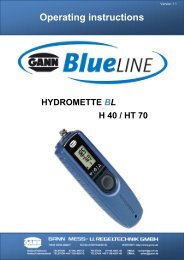
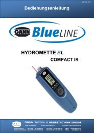
GANN HYDROMETTE <strong>UNI</strong> 1 + <strong>UNI</strong> 2<br />
Operating instructions
All copyrights reserved<br />
Reproduction of this manual, also in part, by print, copying or any other procedure<br />
is not permitted unless approved in writing by GANN <strong>Mess</strong>- u. Regeltechnik GmbH.<br />
This manual has been most carefully composed. The manufacturer and/or supplier<br />
assumes no liability, however, for possible misprints or errors.<br />
Copyright by GANN <strong>Mess</strong>- u. Regeltechnik GmbH.<br />
Stuttgart, Federal Republic of Germany<br />
2
Technical Specifications - Hydromette <strong>UNI</strong> 1<br />
(1) MS Connection Socket for connection of temperature probes PT 100,<br />
all active electrodes and infrared sensor IR 40<br />
(2) LCD Readout for all measurements<br />
(3) Selector Switch »position M«<br />
for measurements using the following active electrodes:<br />
MH 34 for moisture measurements on coniferous<br />
wood in the range between 40 and 200 % m.c.<br />
MB 35 for non-destructive moisture measurements of<br />
concrete surfaces<br />
B 50 for non-destructive moisture measurements of set<br />
inorganic construction materials (concrete, cement floor-<br />
ing, etc.)<br />
RF-T 28 for air humidity measurements,<br />
RF-T 31 for air humidity measurements,<br />
RF-T 32 for air humidity measurements,<br />
IR 40 for surface temperature measurements with infrared<br />
sensor,<br />
»position 200°«<br />
for temperature measurements up to 200 °C with elec -<br />
trodes RF-T 28, RF-T 31, RF-T 32 and temperature pro-<br />
bes PT 100,<br />
4
»position 600°«<br />
for temperature measurements up to 600 °C using<br />
temperature probes PT 100,<br />
»position Batt«<br />
(4) Measuring Key ON/OFF<br />
Battery Check<br />
for battery check.<br />
Set selector switch (3) to position »Batt« and press measuring key (4). The reading displayed<br />
should be higher than 7.5 digits. If it is 7.5 digits or lower, the battery is exhausted and should be<br />
replaced or recharged if a rechargeable battery is being used. The cover of the battery<br />
compartment can be lifted by means of a coin inserted into the slot. It is recommendable to replace<br />
or recharge the battery once the reading of the battery check is below 8 digits.<br />
Power Source<br />
The meter is fitted, as standard, with a 9 V dry battery IEC 6 F 22 or IEC 6 LF 22.<br />
It is recommended to use alkali-mangan batteries.<br />
A rechargeable nickel-cadmium battery can be fitted (optional accessory). It can be recharged from<br />
any A.C. lighting supply socket by means of the charging unit supplied with this special battery.<br />
Calibration<br />
The meter is fitted with an electronic setting device, making manual calibration or adjustment<br />
unnecessary.<br />
5
Measuring ranges<br />
Wood Moisture, position »M«: 40 - 200 % m.c. on coniferous wood using active<br />
electrode MH 34<br />
Structural Moisture, position »M«: 0 - 199 digits non-destructive measurement<br />
with active electrode B 50/B60<br />
0,3 - 8,5 % of dry weight with active electrode<br />
B 50 and conversion table<br />
1 - 8 % of dry weight with active electrode<br />
MB 35 on non-destructive surface<br />
measurement of concrete<br />
Air Humidity, position »M«: 7 - 98 % R.H. with live electrodes RF-T 28,<br />
RF-T 31, RF-T 32 and RF-T 36<br />
Temperature 1, position »200°«: -200 - +200 °C with temperature probes PT 100<br />
Temperature 2, position »600°«: -200 - +600 °C with temperature probes PT 100<br />
Temperature 3, position »M«: -20,0 - +200 °Cwith infrared sensor IR 40.<br />
If the measured value exceeds the measuring capacity, the figure »1« appears on the left side of<br />
the display screen (2).<br />
Dimensions<br />
Plastic casing: Length 140 mm x Width 90 mm x Height 42/50 mm.<br />
Weight: about 220 g without accessory.<br />
6
Technical Specifications - Hydromette <strong>UNI</strong> 2<br />
(1) BNC Connection Socket for connection of electrodes designed for testing set build-<br />
ing materials according to the resistance method<br />
(2) MS Connection Socket for connection of temperature probes PT 100, all active<br />
electrodes and infrared sensor IR 40<br />
(3) LCD Readout for all measurements<br />
(4) Selector Switch »position B«<br />
for measurement of set building materials according to the<br />
resistance measuring method<br />
»position M«<br />
for measurements using the following active electrodes:<br />
MH 34 for moisture measurements on coniferous wood in<br />
the range between 40 and 200 % m.c.<br />
MB 35 for non-destructive moisture measurements of<br />
concrete surfaces<br />
B 50/B 60 for non-destructive moisture measurements of<br />
set inorganic construction materials (concrete, cement<br />
flooring, etc.)<br />
»position M«<br />
RF-T 28 for air humidity measurements,<br />
RF-T 31 for air humidity measurements,<br />
8
»position M«<br />
RF-T 32 for air humidity measurements,<br />
RF-T 36 for air humidity measurements,<br />
IR 40 for surface temperature measurements with infrared<br />
sensor,<br />
»position 200°«<br />
for temperature measurements up to 200 °C with elec -<br />
trodes RF-T 28, RF-T 31, RF-T 32, RF-T 36 and<br />
temperature probes PT 100,<br />
»position 600°«<br />
for temperature measurements up to 600 °C using pro bes<br />
PT 100,<br />
»position Batt«<br />
(5) Measuring Key ON/OFF<br />
Battery Check<br />
for battery check.<br />
Set selector switch (4) to position »Batt« and press measuring key (5). The reading displayed<br />
should be higher than 7.5 digits. If it is 7.5 digits or lower, the battery is exhausted and should be<br />
replaced or recharged if a rechargeable battery is being used. The cover of the battery<br />
compartment can be lifted by means of a coin inserted into the slot.<br />
It is recommendable to replace or recharge the battery once the reading of the battery check is<br />
below 8 digits.<br />
9
Power Source<br />
The meter is fitted, as standard, with a 9 V dry battery IEC 6 F 22 or IEC 6 LF 22. It is<br />
recommended to use alkali-mangan batteries. A rechargeable nickel-cadmium battery can be fitted<br />
(optional accessory). It can be recharged from any A.C. lighting supply socket by means of the<br />
charging unit supplied with this special battery.<br />
Calibration<br />
The meter is fitted with an electronic setting device, making manual calibration or adjustment<br />
unnecessary.<br />
Measuring ranges<br />
Structural Moisture, position »B«: 0 - 80 digits with graphs for converting read<br />
ings into percent of moisture for<br />
various building materials<br />
Structural Moisture, position »M«: 0 - 199 digits non-destructive measurement<br />
with active electrode B 50/B60<br />
0,3 - 8,5 % of dry weight with live electrode<br />
B 50 and conversion table<br />
1 - 8 % of dry weight with live electrode<br />
MB 35 on non-destructive surface<br />
measurement of concrete<br />
Wood Moisture, position »M«: 40 - 200 % for measurement on coniferous<br />
wood using the active electrode<br />
MH 34<br />
Air Humidity, position »M«: 7 - 98 % R.H. with active electrodes RF-T 28,<br />
RF-T 31, RF-T 32 and RF-T 36<br />
10
Temperature 1, position »200°«: -200 - +200 °C with temperature probes PT 100<br />
Temperature 2, position »600°«: -200 - +600 °C with temperature probes PT 100<br />
Temperature 3, position »M«: -20,0 - +200 °Cwith infrared sensor IR 40.<br />
If the measured value exceeds the measuring capacity, the figure »1« appears on the left side of<br />
the display screen (3).<br />
Dimensions<br />
Plastic casing: Length 140 mm x Width 90 mm x Height 42/50 mm.<br />
Weight: about 220 g without accessory.<br />
General instructions for <strong>UNI</strong> 1 and <strong>UNI</strong> 2<br />
Admissible ambient temperatures<br />
Storage: 5 to 40 °C; temporarily -10 to 60 °C<br />
Operation: 0 to 50 °C, short term -10 to 60 °C not c ondensing<br />
The meter including accessory must not be stored or used in aggressive air or air contaminated by<br />
solvents.<br />
General Remark<br />
The instructions for use of the meter and of the electrodes should be carefully observed to avoid<br />
measuring errors which may occur when trying to simplify the measuring procedure.<br />
Warning<br />
Make sure in any case prior to drilling holes for measuring probes or before driving electrode pins<br />
into walls, ceilings or floors that this happens away from power lines, water pipings or other supply<br />
pipes.<br />
11
Measuring Electrodes and Other Accessory<br />
Active electrode MH 34 (Ref.No. 3350)<br />
with integrated measuring circuit, for measurement of high moisture<br />
contents in coniferous wood, specially in case of water-borne storage<br />
and pre-sorting of freshly cut timber for kiln drying.<br />
Measuring range: 40 to 200 % m.c.<br />
12
Active electrode B 50 (Ref. No. 3750)<br />
with integrated measuring circuit, designed for non-destructive<br />
location of moisture concentration in construction materials and<br />
moisture distribution in walls, ceilings and floors.<br />
It works according to a patented measuring procedure and generates a<br />
concentrated high frequency field with substantial penetration depth.<br />
Measuring range: 0 to 199 digits, classification by table,<br />
0.3 to 8.5 % of dry weight, conversion into % of<br />
moisture by table.<br />
0.3 to 6.5 % CM, conversion by table according<br />
to material tested.<br />
13
Active electrode B 60 (Ref. No. 3760)<br />
with integrated measuring circuit, designed for non-destructive<br />
location of moisture concentration in construction materials and<br />
moisture distribution in walls, ceilings and floors.<br />
It works according to a patented measuring procedure and<br />
generates a concentrated high frequency field with substantial<br />
penetration depth.<br />
With built-in limit value selector and acoustic signal generator.<br />
Setting range: 20 to 140 digits.<br />
Measuring ranges: 0 to 199 digits by table.<br />
0.3 to 8.5 % of dry weight conversion by<br />
table according to material tested.<br />
0.3 to 6.5 % CM, conversion by table<br />
according to material tested.<br />
14
Active electrode MB 35 (Ref. No. 3770)<br />
with integrated measuring circuit, designed for surface measure-<br />
ment of concrete, in particular prior to coating or gluing.<br />
Measuring range: 1 to 8 % m.c. of dry weight according to oven<br />
test, direct display, no conversion table required.<br />
Test Standard (Ref. No. 6073)<br />
for checking the active electrode MB 35.<br />
15
Special electrode RF-T 28 (Ref.No. 3155)<br />
with integrated measuring circuit, for measurement of air humidity<br />
and air temperature, complete with connection cable.<br />
Measuring range: 7 to 98 % R.H. and -10 to +80 °C<br />
Response time: about 20 seconds for 90 % of the humidity<br />
difference at an ambient temperature of 20 °C,<br />
or about 120 seconds for 90 % of temperature<br />
variation.<br />
Filter Cap (Ref. No. 3156)<br />
of sintered bronze for use with electrode RF-T 28 in dust laden<br />
air or at high air speed.<br />
16
Special electrode RF-T 31<br />
for measurement of atmospheric moisture, water activity value or<br />
equilibrium moisture in bulk materials and solid substances, e.g.<br />
brickwork and other building materials.<br />
Measuring range: 7 to 98 % R.H.<br />
-10 to +80 °C.<br />
Sensor tube: dia. 10 mm<br />
Sintered filter tip 32 mm long.<br />
Insertion length 250 mm (Ref. No. 3131)<br />
Insertion length 500 mm (Ref. No. 3132)<br />
Bore hole adapter<br />
with closing plug, for use with plug-in sensor RF-T 31 for equilibrium<br />
moisture measurement in brick-work or building materials.<br />
For bore holes up to 150 mm in depth (Ref. No. 5615)<br />
For bore holes up to 250 mm in depth (Ref. No. 5625)<br />
For bore holes up to 500 mm in depth (Ref. No. 5650)<br />
17
Blade Sensor RF-T 32<br />
for measurement of atmospheric humidity, water activity value and<br />
equilibrium moisture in paper, leather, textile and tobacco stores, etc.<br />
Measuring range: 7 to 98 % R.H.<br />
-10 to +80 °C.<br />
Flat elliptical probe abt. 10 x 4 mm.<br />
Insertion length 250 mm (Ref. No. 3133)<br />
Insertion length 500 mm (Ref. No. 3134)<br />
Sensor Check<br />
Test and calibrating box for<br />
Probe RF-T 28 (Ref. No. 5728)<br />
Probe RF-T 31 (Ref. No. 5731)<br />
Probe RF-T 32 (Ref. No. 5732)<br />
Test and Calibrating Fluid<br />
for checking and recalibrating all electrodes type RF-T.<br />
Package of 5 ampoules of test fluid for sensor check, including<br />
absorbing fleece, sufficient for 5 tests or recalibrations.<br />
SCF 30 for the range of 10 to 50 % R.H. (Ref. No. 5753)<br />
SCF 70 for the range of 50 to 90 % R.H. (Ref. No. 5757)<br />
SCF 90 for the range of 80 to 98 % R.H. (Ref. No. 5759)<br />
18
Special electrode RF-T 36 (Ref. No. 3136)<br />
for measurement of air humidity and air temperature, water activity<br />
value or equilibrium moisture in rooms, warehouses or solid<br />
substances (e.g. concrete, subflooring, masonry, etc.)<br />
Measuring Range: 5 to 98 % R.H.<br />
-5 to +60 °C<br />
Dimensions: 82 x 80 x 55 mm<br />
Sensor tube: length 55 mm, dia. 12 mm<br />
19
Infrared Surface Temperature Sensor IR 40<br />
(Ref. No. 3150)<br />
Contactless temperature measurement from -20 to +199.9 °C,<br />
resolution 0.1 °C, emissivity permanently set at 9 5 %, ratio of<br />
measured area to distance 2.5:1 (Ø 45 mm at a distance of<br />
100 mm), sensor length 185 mm x 36 x 33 mm, coiled cable<br />
320/1200 mm.<br />
An ideal sensor for detection of heat bridges, determination of<br />
the dew point temperature, measurement of live, moving or vi-<br />
brating components as well as measurement of components<br />
with low heat capacity, e.g. wood, glass, insulating materials,<br />
for location of the position of the heating tubes of a floor heat-<br />
ing, etc.<br />
Matt-black stickers IR 30/E 95 (Ref. No. 5833)<br />
Measurement spot 30 mm Ø, emissivity 95 %, e.g. for meas-<br />
urement of metallic surfaces.<br />
20
Pt 100 Temperature Probes<br />
Temperature Probe ET 10 (Ref. No. 3165)<br />
Robust stick-in temperature probe for solid and bulk materials<br />
and liquids, measuring range -50 to +250 °C .<br />
Temperature Probe TT 40 (Ref. No. 3180).<br />
Robust immersion and combustion gas temperature probe with<br />
long sensor tube, measuring range -50 to +350 °C<br />
Temperature Probe LT 20 (Ref. No. 3190)<br />
Quick responding air/gas temperature probe with long sensor<br />
tube, measuring range -20 to +200 °C.<br />
Temperature Probe TT 30 (Ref. No. 3185)<br />
Robust immersion and combustion gas temperature probe with<br />
short sensor tube, measuring range -50 to +350 °C.<br />
Temperature Probe ET 50 (Ref. No. 3160)<br />
Quick responding air/gas temperature probe for soft solid sub-<br />
stances, bulk materials and fluids, measuring range -50 to 250 °C.<br />
Temperature Probe OTW 90 (Ref. No. 3175)<br />
Angled special surface temperature probe, e.g. for veneer<br />
presses, etc., measuring range -50 to +250 °C.<br />
Temperature Probe OT 100 (Ref. No. 3170)<br />
Spring loaded, low mass surface temperature probe, e.g. for<br />
wall surfaces, etc., measuring range -50 to +250 °C.<br />
21
Silicone Heat Conducting Paste (Ref. No. 5500)<br />
To improve heat transmission on rough surfaces or where there<br />
are contact problems. Unconditionally recommended with OT 100.<br />
Flexible Temperature Probes with Teflon insulated connection<br />
cable, for solid and bulk materials as well as liquids up to 120 °C.<br />
FT 2 with Teflon cable 2 m long<br />
(Ref. No. 3195)<br />
FT 5 with Teflon cable 5 m long<br />
(Ref. No. 3196)<br />
FT 10 with Teflon cable 10 m long<br />
(Ref. No. 3197)<br />
FT 20 with Teflon cable 20 m long<br />
(Ref. No. 3198)<br />
22
Use of Active Electrode MH 34<br />
for measurement of high moisture contents (above 40 % m.c.) in coniferous wood<br />
The active electrode MH 34 has been developed specially for measurement of very high moisture<br />
contents in coniferous wood (pine, fir, spruce). It is suitable particularly for pre-sorting freshly cut<br />
timber for kiln drying and for monitoring water-borne borne storage.<br />
The measuring range extends from 40 to 199 % m.c. and the reading is displayed direct in per<br />
cents of moisture. Moisture values below 40 % m.c. are beyond the measuring capacity of this<br />
special electrode and readings below 40 % m.c. should, therefore, be disregarded. For<br />
measurements in the range below 40 % m.c. the electrodes M 18 and M 20 should be used.<br />
The active electrode MH 34 is equipped and also adjusted to pins 23 mm in length, and the<br />
readings obtained represent the average moisture content of those section of the board or piece of<br />
wood penetrated by the pins. We do not recommend using longer or shorter pins as this will affect<br />
the accuracy of reading.<br />
Press, or drive cautiously, both pins into the wood to be measured until both cap nuts touch it.<br />
Connect electrode to the meter socket (1) (<strong>UNI</strong> 1) or (2) (<strong>UNI</strong> 2) and set selector switch (3) (<strong>UNI</strong> 1)<br />
or (4) (<strong>UNI</strong> 2) to position »M«. Then press measuring key (4) (<strong>UNI</strong> 1) or (5) (<strong>UNI</strong> 2) and read result<br />
in per cent of moisture.<br />
When withdrawing the electrode, the pins can be loosened by slight sideways rocking movements<br />
across the grain. The cap nuts should be tightened by means of a spanner prior to a series of<br />
measurements.<br />
23
Instructions For Non-Destructive Measurement of the Moisture Con-<br />
tent of Building Materials Using the Electrodes MB 35 and B 50/B 60<br />
Set selector switch (3) (<strong>UNI</strong> 1) or (4) (<strong>UNI</strong> 2) to position »M«.<br />
Connect electrode to meter socket (1) (<strong>UNI</strong> 1) or (2) (<strong>UNI</strong> 2) and apply it as described hereinafter.<br />
Press measuring key (4) (<strong>UNI</strong> 1) or (5) (<strong>UNI</strong> 2) and read result displayed by LCD readout (2)<br />
(<strong>UNI</strong> 1) or (3) (<strong>UNI</strong> 2).<br />
Active Electrode MB 35<br />
The active electrode MB 35 has specially been developed for surface moisture measurement on<br />
concrete and sub-floorings and are suitable particularly for moisture checks prior to coating or<br />
gluing. The measuring range extends from 1.0 to 8.0 % of dry weight (according to oven test). The<br />
reading is displayed direct in per cent of moisture.<br />
The electrode is fitted, as standard equipment, with the surface measuring caps M 20-OF 15 with<br />
elastic contact pads of conductive plastic material. The pads are glued on their support which in<br />
turn are screwed on the electrode handle. Make sure that the measuring caps are properly<br />
screwed down. Exchange the elastic measuring pads in case of wear or damage. Fix the new pads<br />
on the support plate by means of a commercially available instant adhesive on cyanate basis.<br />
Use of active electrode MB 35<br />
Connect electrode to the meter and press the measuring pads firmly on the concrete. Press<br />
measuring key and read off result in per cent of dry weight. The surface of the concrete should be<br />
cleaned from dust and separating agents or other contaminations to ensure correct measuring<br />
results.<br />
24
Active Electrode B 50 und B 60<br />
The active electrodes B 50 and B 60 are dielectric moisture sensor with integrated circuitry. It is<br />
intended specifically for determining moisture absorption and moisture distribution in building<br />
materials such as for example brickwork, concrete, screed, wood, insulating materials, etc.<br />
The basis of measurement is the dielectric constant measurement method. Between the ball<br />
electrode and the material to be measured with which it comes into contact, a measurement field is<br />
set up, which is affected by the density of the building material to be measured and its moisture<br />
content. If the density of the material is constant, changes in the capacity field can be matched to a<br />
change in the moisture content of the material being measured.<br />
The measuring range extends from 0 to 199 digits, i.e. the displayed values are relative values.<br />
They indicate the distinction between dry and moist building material. The higher the measured<br />
value, the higher the moisture content of the material being measured. Drawing conclusions about<br />
the actual moisture content in per cent from the relative measured is only permissible in the case of<br />
a normal drying process.<br />
The bulk density of the building material to be measured is in this case a factor of influence which<br />
has to be taken into account. High bulk densities lead to higher displayed values, independently of<br />
the moisture content.<br />
Use of active electrode B 50 and B 60<br />
In order to avoid influencing of the measurement result by the hand of the operator, the electrode<br />
should only be held by its lower half during checking and measurement. The upper half of the<br />
electrode must remain free.<br />
25
Special feature of the active electrode B 60<br />
The active electrode B 60 is equipped with a selector switch to set a limit value.<br />
It allows in conjunction with the also incorporated acoustic signal generator judgement of the tested<br />
building material without direct sight on the LCD readout.<br />
Whenever the readings exceed the preset limit value, a whistle signal sounds.<br />
In the range between 30 and 70 digits, the signal tolerance is ± 2 digits, and in the range between<br />
80 and 140 digits ± 3 digits.<br />
26
Checking<br />
Unless it is permanently fixed, push the ball rod into the socket on the top of the electrode and<br />
connect the cable to the measuring instrument. Hold the electrode in the air and press the<br />
measuring key of the measuring instrument. It must display a value between -5.0 and 5.0 digits. If it<br />
fails to display an admissible value, increase or, as the case may be, reduce the reading by slightly<br />
turning the potentiometer located behind an opening in the upper half of the grey plastic handle of<br />
the active electrode by means of a small screwdriver.<br />
Measurement<br />
Press the measuring key of the moisture meter and bring the electrode ball into contact with the<br />
surface to be tested. The electrode ball must be in firm contact with the material. As far as possible<br />
the electrode should be held perpendicularly to the surface being measured. In corners<br />
measurement is only possible up to a distance of approx. 4 - 5 cm from the edge. The list below is<br />
intended to serve as a guide to the displayed values to be expected in practice and their<br />
classification:<br />
Wood dry 25 - 40 digits<br />
moist 80 - 140 digits<br />
Living area dry 25 - 40 digits<br />
brickwork moist 100 - 150 digits<br />
Basement brickwork dry 60 - 80 digits<br />
moist 100 - 150 digits<br />
Depending on the bulk density, displays of more than 130 digits would indicate the presence of free<br />
water. In the case of covered metal parts (reinforcing steel, pipes, ducting, plaster supporting strips,<br />
etc.) even if the environment is otherwise dry the display jumps to approximately 80 digits (if the<br />
27
covering is very thin, even higher). This should be taken into account when assessing the<br />
displayed values.<br />
Density<br />
(specific wt.)<br />
of the<br />
building<br />
material<br />
kg/m³<br />
up to 600<br />
600 -1200<br />
1200 -1800<br />
above 1800<br />
Display Values (Digits) in Relation to the Material Bulk Density<br />
Corresponding Relative Air Humidity<br />
30 ⎯⎯-⎯ 50 ⎯⎯⎯⎯ 70 ⎯⎯⎯⎯⎯ 80 ⎯⎯⎯⎯⎯ 90 ⎯⎯⎯⎯ 95 ⎯⎯⎯⎯ 100<br />
very<br />
dry<br />
10 - 20<br />
20 - 30<br />
20 - 40<br />
30 - 50<br />
normal<br />
dry<br />
20 - 40<br />
30 - 50<br />
40 - 60<br />
50 - 70<br />
Display in Digits<br />
semi<br />
dry<br />
40 - 60<br />
50 - 70<br />
60 - 80<br />
70 - 90<br />
28<br />
moist<br />
60 - 90<br />
70 - 100<br />
80 - 100<br />
90 - 120<br />
very<br />
moist<br />
90 - 110<br />
100 - 120<br />
110 -130<br />
120 - 140<br />
wet<br />
more than<br />
100<br />
more than<br />
120<br />
more than<br />
130<br />
more than<br />
140
Display (Digits)<br />
Cement<br />
mortar<br />
Anhydrite<br />
screed<br />
Concrete<br />
B 15, B 25,<br />
B 35<br />
Cement<br />
mortar<br />
Lime<br />
mortar<br />
Lime-cement<br />
plaster<br />
mixture<br />
Gypsum<br />
plaster<br />
weight<br />
%<br />
weight<br />
%<br />
weight<br />
%<br />
weight<br />
%<br />
weight<br />
%<br />
weight<br />
%<br />
weight<br />
%<br />
Display Values (Digits) in Percents of Weight<br />
40 50 60 70 80 90 100 110 120 130<br />
1.8 2.2 2.7 3.2 3.6 4.1 4.5 5.0 5.5 5.9<br />
0.1 0.3 0.6 1.0 1.4 1.8 2.2 2.5 2.9 3.3<br />
1.3 1.9 2.5 3.2 3.8 4.4 5.0 5.6 6.2<br />
1.8 2.7 3.5 4.6 6.0 7.0 7.8<br />
0.6 2.0 3.3 4.5<br />
2.2 3.6 5.0 6.4 7.8 9.2 10.6 11.0<br />
0.3 0.5 1.0 2.0 3.5 6.5 10.0<br />
29
Readings in digits depending on the moisture in weight per cent. The displayed values are guide<br />
values. They refer to a depth of 1.5 to 3 cm in the case of a measurement on the surface and a<br />
normal drying process. Weight percentages are according to an oven test at 105 °C, for gypsum<br />
and anhydrite binders at 40 °C.<br />
Note<br />
The references and tables concerning permissible or customary moisture proportions in practice<br />
contained in the Operating Instructions and the general definitions have been taken from the<br />
specialist literature. No guarantee of correctness can therefore be given. The conclusions each<br />
user may draw for his own purposes from the measurement results are based on the individual<br />
circumstances and the knowledge he has gained from his professional activities.<br />
30
Instructions for Moisture Measurement in Building Materials on the Basis of<br />
the Measurement of the Relative Air Humidity<br />
using the active electrodes RF-T 31 and RF-T 36<br />
Set selector switch (3) (<strong>UNI</strong> 1) or (4) (<strong>UNI</strong> 2) to position »M«.<br />
Connect selected active electrode to the meter socket (1) (<strong>UNI</strong> 1) or (2) (<strong>UNI</strong> 2).<br />
Press measuring key (4) (<strong>UNI</strong> 1) or (5) (<strong>UNI</strong> 2) and read off result displayed (in % R.H.) by the LCD<br />
readout (2) (<strong>UNI</strong> 1) or (3) (<strong>UNI</strong> 2).<br />
Technical specifications<br />
Measuring range: 5 to 98 % R.H. for short periods.<br />
For continuous or long period measurements in<br />
the range above 80 % R.H., a special calibra-<br />
tion is required for the measuring sensors.<br />
Admissible operating temperature -10 °C to +60 °C f or short periods,<br />
for the meter and the electrodes: 0 °C to +50 °C for long periods.<br />
Admissible ambient conditions<br />
for the storage of the meter -10 °C to +60 °C for short periods<br />
and the electrodes: 5 °C to +40 °C for long per iods.<br />
5 % to 98 % R.H. for short periods *)<br />
35 % to 70 % R.H. for long periods *)<br />
*) not condensing<br />
31
Measurement of the Relative Air Humidity /<br />
Water Activity in Building Materials<br />
This method is usually used for depth measurements in old buildings (sandstone, rough stone, wet<br />
walls with efflorescence, etc.) where measurements based on the resistance measurement method<br />
give no reproducible results. For this purpose the active electrode RF-T 31 with special tube<br />
lengths of 250 and 500 mm is used. In the case of measurements over a longer period at several<br />
points or at various depths, the drilled holes should be secured and closed by means of a masonry<br />
sleeve / bore hole adapter.<br />
The method of measuring the relative air humidity / equilibration moisture in screeds is chiefly used<br />
in Great Britain and the Scandinavian countries. The active electrode RF-T 36 has been specially<br />
developed for this. Compared with non-destructive measurement or resistance measurement it is<br />
however very time-consuming and required relatively large holes. Reliability for the floor layer/<br />
finisher is but on the other hand very good, if it is possible to wait for moisture balance (relative air<br />
humidity of the surroundings equal to that of the hole). This method also increases reliability in<br />
cases where there is not adequate information concerning the composition of the screed.<br />
Use of the active electrode RF-T 31<br />
For deep measurements in building materials by means of the relative air humidity, in addition to<br />
the probe with a sensing tube length of 250 or 500 mm a bore hole adapter consisting of a masonry<br />
sleeve of 150, 250 or 500 mm length should be used.<br />
32
For the measurement a blind hole of 16 mm diameter should be drilled down to the required<br />
measuring depth. It is important to use a sharp drill, with a high number of impacts and low speed.<br />
If the hole should heat up strongly it is necessary to wait for temperature equalization (30 - 60<br />
minutes) before taking the measurement. The hole should be cleared of dust (by blowing). Then<br />
the hole adapter should be introduced as far as the end of the hole, pressed in and at the same<br />
time turned to the right. The adapter should be tightened to such an extent that the entire screw<br />
thread sits firmly in the brickwork, concrete, etc. Then the closure rod for sealing or the electrode<br />
RF-T 31 should be inserted.<br />
The moisture balance in the hole is achieved when temperature equalization exists (the same<br />
temperature in the hole, adapter and sensor tube) after approximately 30 minutes. Then the<br />
measurement value can be read off and assessed by means of the following graph.<br />
Use of the active electrode RF-T 36<br />
For the measurement a blind hole of 12 - 14 mm diameter and minimum 25 mm and maximum 50<br />
mm deep must be drilled. The depth of drilling depends on the required measurement depth or<br />
thickness of the screed. Blow the hole clear of dust and wait for temperature equalization. Push the<br />
piece of foam enclosed on to the electrode tube of the probe and adjust the distance and to seal it,<br />
then introduce it into the hole.<br />
The moisture balance in the hole is achieved when temperature equalization exists (the same<br />
temperature in the hole, adapter and sensor tube) after approximately 30 minutes. Then the<br />
measurement value can be read off and assessed by means of the following graph.<br />
33
Damage to the Sensor<br />
The sensor can be rendered irreparable as a result of various mechanical or environmental<br />
influences. These include in particular:<br />
- direct contact between the sensor and the fingers,<br />
- direct contact with solid or adhesive materials or objects,<br />
- measurement in atmospheres containing solvents, oil vapours and other high proportions of<br />
armful substances.<br />
Measuring Errors<br />
Measurements below 20 % relative humidity and above 80 % relative humidity should be avoided<br />
over a long period as far as possible. In order to make exceeding the measuring range particularly<br />
easy to recognize, above 98 % relative humidity a »1« appears on the left hand side of the display<br />
instead of the measured value. Other measured value distortions can occur as a result of screening<br />
with parts of the body (e.g. the hand) or blowing or speaking/breathing in the direction of the<br />
sensor.<br />
Note<br />
The sensor is not designed for continuous measurements above 80 % relative humidity. If<br />
continuous measurements have to be made in extreme regions special adjustments should be<br />
made by means of sensorcheck and a calibration liquid.<br />
35
Instructions for Air Humidity Measurement<br />
using the active electrodes RF-T 28, RF-T 31, RF-T 32 and RF-T 36<br />
Set selector switch (3) (<strong>UNI</strong> 1) or (4) (<strong>UNI</strong> 2) to position »M«.<br />
Connect electrode to the meter socket (1) (<strong>UNI</strong> 1) or (2) (<strong>UNI</strong> 2).<br />
Press measuring key (4) (<strong>UNI</strong> 1) or (5) (<strong>UNI</strong> 2) and read off result displayed (in % R.H.)<br />
by the LCD readout (2) (<strong>UNI</strong> 1) or (3) (<strong>UNI</strong> 2).<br />
Technical Specifications<br />
Measuring range: 5 to 98 % R.H. for short periods.<br />
For continuous or long period measurements in<br />
the range above 80 % R.H., a special calibra-<br />
tion is required for the measuring sensors.<br />
Admissible operating temperature -10 °C to +60 °C f or short periods,<br />
for the meter and the electrodes: 0 °C to +50 °C for long periods.<br />
Admissible ambient conditions<br />
for the storage of the meter -10 °C to +60 °C for short periods<br />
and the electrodes: 5 °C to +40 °C for long per iods.<br />
5 % to 98 % R.H. for short periods *)<br />
35 % to 70 % R.H. for long periods *)<br />
*) not condensing<br />
36
Use of the active electrode RF-T 28<br />
Hold the electrode in the air or fasten it at the desired measurement site and start the measuring<br />
process. For particularly precise measurements, especially below the usual room temperature (abt.<br />
20 °C) or if there are substantial temperature diff erences between the electrode or meter and their<br />
surroundings, they should be exposed to the ambient atmosphere for approx. 10 - 15 minutes until<br />
temperature equalization. The sensor adapts itself to the surrounding atmosphere even in the<br />
switched-off condition.<br />
Response time of the air humidity sensor<br />
The response time of the sensor is very short so even gently moving air (generated by a slightly<br />
opened door or a window being not tight) may affect the reading. This is why no absolute standstill<br />
of the value displayed can be achieved unless the sensor is installed in an airtight box.<br />
The response time of the sensor in gently moving air is as follows for ambient temperatures from<br />
20 °C to 25 °C<br />
for 90 % of the humidity difference, approx. 20 seconds,<br />
for 95 % of the humidity difference, approx. 30 seconds.<br />
The adjustment time in still air or at very low air movement can be reduced by moving or turning<br />
the electrode (ventilating the sensor).<br />
Filter cap for electrode RF-T 28<br />
For measurements in dust laden air, at emission of harmful substances or at high air speed, a<br />
sintered filter cap can be fitted after removal of the protection cap with venting slots. For protection<br />
of the sintered filter, fix then the plastic cap again.<br />
If the filter becomes dirty it can be washed in residue-free cleaning liquid and/or blown from inside<br />
outwards with compressed air. With the sintered filter inserted, the response time will be<br />
considerably prolonged.<br />
37
Use of the active electrode RF-T 31<br />
The sensor RF-T 31 can be supplied with insertion length of 250 or 500 mm and is mainly used for<br />
measuring the relative air humidity or the AW value in places difficult of access, in air ducts, in bulk<br />
materials or, in combination with a special adapter, in solid substances (e.g. brickwork, concrete,<br />
etc.).<br />
Hold the electrode at the point of measurement in the air or insert it or attach it at the required point<br />
with a fixture and start the measurement process. For particularly precise measurements, in<br />
particular at temperatures below usual room temperature (abt. 20 °C) or when there are<br />
considerable temperature differences between the actual temperature of the electrode or of the<br />
measuring instrument and that of the surrounding atmosphere, the instrument with its electrode<br />
should be exposed to the ambient climate for approximately 10 to 15 minutes or until temperature<br />
equalization.<br />
Here too, the sensor adapts itself to the surrounding atmosphere without being switched on. If it<br />
becomes dirty, the sintered filter cap can be washed in residue free cleaning liquid and/or blown<br />
from inside outwards with compressed air.<br />
Response time of the air humidity sensor RF-T 31<br />
The response time is delayed by the sintered filter cap. In exceptional cases it can be unscrewed.<br />
However, if this is done the danger of damage to the sensor is increased considerably. The<br />
response time of the air humidity sensor in moving air, with an ambient temperature of 20 to 25 °C<br />
is<br />
- for 90 % of the moisture difference without filter approx. 20 sec., with filter approx. 5 min., and<br />
- for 95 % of the moisture difference without filter approx. 30 sec., with filter approx. 15 min.<br />
38
Use of the active electrode RF-T 32<br />
The sensor RF-T 32 is available with insertion lengths of 250 and 500 mm and is mainly used for<br />
measuring the relative air humidity or the AW value in places difficult of access or in stacks of<br />
paper, leather, textile, tobacco, etc.<br />
Hold the electrode at the point of measurement in the air or place it at the required point and start<br />
the measurement process. For particularly precise measurements, in particular at temperatures<br />
below usual room temperature (abt. 20 °C) or when t here are considerable temperature differences<br />
between the actual temperature of the electrode or of the measuring instrument and that of the<br />
surrounding atmosphere, the instrument with its electrode should be exposed to the surrounding<br />
atmosphere for approximately 10 to 15 minutes or until temperature equalization. The sensor<br />
adapts<br />
itself to the surrounding atmosphere even if it is switched off.<br />
Note<br />
If it becomes dirty, the filter cloth inserted cannot be washed in cleaning liquids and /or blown clear<br />
with compressed air from inside to outside. Therefore its use in dusty media should be avoided.<br />
Cleaning should only be carried out from outside using a soft brush.<br />
Response time of the air humidity sensor RF-T 32<br />
The response time is delayed by the filter cloth and the metal tube. The response time of the air<br />
humidity sensor in moving air, with an ambient temperature of 20 to 25 °C is:<br />
- approx. 3 minutes for 90 % of the humidity difference, and<br />
- approx. 10 minutes for 95 % of the humidity difference.<br />
39
Use of the active electrode RF-T 36<br />
The electrode RF-T 36 was developed among other things for semi-stationary (electrode remains<br />
at the measuring point - display unit is mobile when in use) air humidity and air temperature<br />
measurement in interiors, storage bays, etc.<br />
Attach the electrode at the measuring location or at the required point and start the measuring<br />
process. For particularly precise measurements, in particular at temperatures below room<br />
temperature (abt. 20 °C) or if there are significan t temperature differences between the<br />
temperature of the electrode itself and that of the surrounding atmosphere (measurement<br />
immediately after assembly) the electrode should be exposed to the surrounding atmosphere for<br />
approximately 10 to 15 minutes or until temperature equalization. The sensor adapts itself to the<br />
surrounding atmosphere even while being switched-off.<br />
Response time of the air humidity sensor RF-T 36<br />
The response time is delayed by the filter cap. In exceptional cases it can be unscrewed.<br />
However, if this is done the danger of damage to the sensor is increased considerably.<br />
The response time of the air humidity sensor in moving air, with an ambient temperature<br />
of 20 to 25 °C is:<br />
- approx. 20 sec. for 90 % of the humidity difference without filter or<br />
- approx. 3 min. with filter, and<br />
- approx. 30 sec. for 95 % of the humidity difference without filter, or approx. 10 min. with filter.<br />
40
Note<br />
If it becomes dirty, the inserted filter cloth can only be washed in distilled water and/or blown clear<br />
with slight excess pressure from inside outwards. Therefore its use in very dusty media should be<br />
avoided. Preferably the cleaning should be carried out from outside using a soft brush.<br />
41
Air<br />
temperature<br />
°C<br />
Synoptical table of dew point temperatures<br />
as dictated by the air temperature and air relative humidity<br />
Dew point temperature in °C at an air relative humi dity of<br />
30 %<br />
°C<br />
40 %<br />
°C<br />
50 %<br />
°C<br />
60 %<br />
°C<br />
42<br />
70 %<br />
°C<br />
80 %<br />
°C<br />
90 %<br />
°C<br />
Saturation moisture<br />
= quantity of water<br />
in g/m³<br />
+30 10,5 14,9 18,5 21,2 24,2 26,4 28,5 30,4<br />
+28 8,7 13,1 16,7 19,5 22,0 24,2 26,2 27,2<br />
+26 7,1 11,3 14,9 17,6 19,8 22,3 24,2 24,4<br />
+24 5,4 9,5 13,0 15,8 18,2 20,3 22,2 21,8<br />
+22 3,6 7,7 11,1 13,9 16,3 18,4 20,3 19,4<br />
+20 1,9 6,0 9,3 12,0 14,3 16,5 18,3 17,3<br />
+18 0,2 4,2 7,4 10,1 12,4 14,5 16,3 15,4<br />
+16 -1,5 2,4 5,6 8,2 10,5 12,5 14,3 13,6<br />
+14 -3,3 -0,6 3,8 6,4 8,6 10,6 12,4 12,1<br />
+12 -5,0 -1,2 1,9 4,3 6,6 8,5 10,3 10,7<br />
+10 -6,7 -2,9 0,1 2,6 4,8 6,7 8,4 9,4<br />
+8 -8,5 -4,8 -1,6 0,7 2,9 4,8 6,4 8,3<br />
+6 -10,3 -6,6 -3,2 -1,0 0,9 2,8 4,4 7,3<br />
+4 -12,0 -8,5 -4,8 -2,7 -0,9 0,8 2,4 6,4<br />
+2 -13,7 -10,2 -6,5 -4,3 -2,5 -0,8 0,6 5,6<br />
0 -15,4 -12,0 -8,1 -5,6 -3,8 -2,3 -0,9 4,8
Test and Calibrating Instructions for the Relative Humidity Circuitry<br />
of the Electrodes RF-T 28, 31 and 32 Using the Sensorcheck<br />
General Comments<br />
In general one has to differentiate between a test, a possibly necessary re-calibration and a special<br />
calibration for continuous measurement of more than 80 % humidity. Three test and calibrating<br />
liquids are available for the ranges of 10 to 50 %, 50 to 90 % and 80 to 98 %. The latter liquid is<br />
intended for special calibration of the high humidity range and is not to be used for general test or<br />
calibrating purposes. For testing or calibration of the standard moisture range, the liquid SCF 70 is<br />
to be employed.<br />
During testing or calibration, the electrode, the sensorcheck and the liquid must be of the same<br />
temperature. This temperature must be maintained throughout the procedure. Changes of<br />
temperature may be caused by a draft, by breathing or blowing or by holding the electrode tube,<br />
the sensorcheck or the liquid-ampoule in one's hand. Wrapping these components in Styropor or<br />
similar insulating material is recommended.<br />
Please follow the instructions stated on the wrapper of the liquid-ampoule regarding test, calibration<br />
and nominal value data closely.<br />
43
Testing<br />
Different sensorcheck top pieces are required for each of the three types of electrodes.<br />
The following test sequence must be observed:<br />
1. Unscrew sensorcheck top from bottom.<br />
2. Electrode RF-T 28: Carefully pull-off the protective cap. If used, remove the dust cap first.<br />
Electrode RF-T 31: Unscrew the sinter filter cap and withdraw it carefully only along the<br />
axis of the tube extension. Tilting the sinter filter may cause damage to<br />
the moisture sensor.<br />
Electrode RF-T 32: This electrode requires no special preparation. Do not dismantle it.<br />
3. Electrode RF-T 28: Plug the top of the sensorcheck to the electrode and push it on lightly<br />
(conical fit).<br />
Electrode RF-T 31: Plug the top of the sensorcheck over the moisture sensor of the elec-<br />
trode and screw to the thread of the electrode tubing. Use no force and<br />
do not tighten it securely.<br />
Electrode RF-T 32: Insert the oval tubing of the electrode, perforated side downward, hori-<br />
zontally into the top part of the sensorcheck. Make sure that the perfora-<br />
tions are inside the sensorcheck. To avoid temperature change, do not<br />
handle the metal tubing of the electrode unnecessarily.<br />
4. Store the electrode, the sensorcheck and the test liquid at a temperature-stable location until<br />
all components have assumed the temperature given on the packaging of the test-ampoule<br />
(e.g. 23 °C ± 2°C.).<br />
5. Remove a piece of fleece from the plastic bag and place it in the bottom section of the<br />
sensorcheck. Close the plastic bag containing the remaining pieces of fleece tightly.<br />
44
6. Pick an ampoule containing the desired type of test liquid. Hold it vertically and tap it lightly to<br />
return all liquid into the lower part of the ampoule. Hold the ampoule tightly and break its neck<br />
off at the white marking. Pour all of the liquid in the ampoule onto the fleece in the lower part<br />
of the sensorcheck.<br />
7. Screw the lower part of the sensorcheck onto the upper part. To prevent a change of<br />
temperature hold the items as briefly as possible or wear gloves.<br />
8. Connect the electrode to the Hydromette by means of its cable.<br />
9. Electrode RF-T 28: While avoiding a change of temperature, allow the electrode to be ex-<br />
posed to the atmosphere of the sensorcheck as stated on the packaging<br />
(e.g. 10 min. ± 1 min.).<br />
Electrode RF-T 31: Proceed in the same way as with the electrode RF-T 31.<br />
Electrode RF-T 32: When testing the RF-T 32 electrode, double the exposure time stated on<br />
the packaging of the ampoule (e.g. 20 min. ± 2 min.). Avoid a change of<br />
temperature.<br />
10. At the end of the above stated exposure time, press the measuring key of the Hydromette and<br />
obtain an air humidity reading. A deviation of ± 2 % from the nominal value given on the<br />
package of the ampoule is permissible.<br />
45
Recalibration<br />
Re-calibration of the sensors used with the electrodes RF-T is hardly ever necessary. Existing<br />
deviations of measurement are almost always caused by improper storage of the electrode in<br />
surroundings which are too dry or too moist. Prior to every recalibration of the electrode, it should<br />
be exposed to a conditioning process. This means exposing the electrode to an average relative<br />
humidity of from 45 % to 65 % R.H. for 24 hours. If the measured humidity is too low by more than<br />
5 %, it is suggested to expose the electrode to a high humidity of 70 % to 75 % R.H. for the first 12<br />
hours.<br />
If the measured humidity is too high, a similar conditioning process in a dry climate of 40 % to 45 %<br />
R.H. is recommended. At completion of such a conditioning process, a re-calibration may be found<br />
unnecessary, as the original deviation had been caused by the effect of sorption.<br />
If re-calibration is needed, the test and calibration fluid SCF 70 should be used. Preparation and<br />
general procedure is as outlined in paragraph »Testing« 1 to 9 c.<br />
Re-calibration is done by means of a small straight screwdriver with a maximum blade width of 2<br />
mm (3/16 inch). A trimpotentiometer is located behind an opening in the middle of the black plastic<br />
handle. By careful, clockwise turning of the trimpotentiometer, the measured humidity can be<br />
increased; it can be decreased by turning counter-clockwise. One full rotation corresponds<br />
approximately to a change of 7 % R.H. The re-calibration should begin exactly at the end of the<br />
exposure time of 10 resp. 20 minutes and should take no longer than 2 to 4 minutes.<br />
46
Special Calibration<br />
Special calibration may become necessary if continuous measurements of high humidity (more<br />
than 80 % R.H.) or of very low humidity (less than 35 % R.H.) are to be conducted. Test liquids<br />
SCF 90 and SCF 30 are available for this purpose. To eliminate measuring or calibrating mistakes<br />
caused by the sorption effect, it is necessary to allow an exposure time of 6 to 7 hours for the<br />
electrode RF-T 32.<br />
This special calibration is done, under consideration of the longer exposure times, following the<br />
instructions given in paragraphs »Testing« and »Re-Calibration«.<br />
To return a specially calibrated electrode to normal usage, it must be re-calibrated according to<br />
paragraph »Re-Calibration« after it had been subjected to a conditioning period of 24 hours.<br />
47
Operating Instructions for Temperature Measurement<br />
Measurement using active electrodes RF-T 28, RF-T 31 and RF-T 32<br />
Set selector switch (3) (<strong>UNI</strong> 1) or (4) (<strong>UNI</strong> 2) to position »200 °C«.<br />
Connect electrode to meter socket (1) (<strong>UNI</strong> 1) or (2) (<strong>UNI</strong> 2).<br />
Press measuring key (4) (<strong>UNI</strong> 1) or (5) (<strong>UNI</strong> 2) and read off result in °C displayed by the LCD<br />
readout (2) (<strong>UNI</strong> 1) or (3) (<strong>UNI</strong> 2).<br />
Measurement using PT 100 temperature probes<br />
Set selector switch (3) (<strong>UNI</strong> 1) or (4) (<strong>UNI</strong> 2) to position »200 °C« or »600 °C«.<br />
Connect temperature probe to meter socket (1) (<strong>UNI</strong> 1) or (2) (<strong>UNI</strong> 2).<br />
Press measuring key (4) (<strong>UNI</strong> 1) or (5) (<strong>UNI</strong> 2) and read off result in °C displayed by the LCD<br />
readout (2) (<strong>UNI</strong> 1) or (3) (<strong>UNI</strong> 2).<br />
Measurement using active electrode IR 40<br />
Set selector switch (3) (<strong>UNI</strong> 1) or (4) (<strong>UNI</strong> 2) to position »M«.<br />
Connect infrared temperature probe to the meter socket (1) (<strong>UNI</strong> 1) or (2) (<strong>UNI</strong> 2).<br />
Adjust temperature probe to the desired measuring spot and press measuring key (4) (<strong>UNI</strong> 1) or<br />
(5) (<strong>UNI</strong> 2). Read off result in °C.<br />
48
General Information About Temperature Measurement<br />
A temperature balance must be achieved between the measuring sensor and the object to be<br />
measured, for correct readings to be made. This is easy to achieve when measuring liquids in large<br />
quantities or large objects with a high heat content. One must ensure that the sensor tube and<br />
head are not affected by another temperature such as ambient air temperature.<br />
Therefore, it is recommended that the sensor be totally immersed or a screen be fitted to the tube.<br />
This screen can be made of polyester or of foam rubber about 3 cm dia., and sufficiently long to<br />
protect the exposed length of the tube which will be pushed through the middle. In the case of<br />
surface measurements with temperature probe OT 100, the block of polyester or rubber foam with<br />
a length of side of at least 30 mm will be sufficient to protect against convection heat or cold when<br />
taking temperature measurements on walls.<br />
In the case of materials which are poor heat conductors or of low heat content (e.g. rockwool,<br />
glasswool, etc.) it is often not possible to achieve a correct temperature measurement with<br />
electrical sensors. To obtain utilizable results, it may become necessary either to take into account<br />
the ambient temperature or to carry out approximate measurements.<br />
When measuring insulating materials whose surface temperature generally corresponds to the<br />
ambient temperature, the stick-in temperature probe ET 50 should be used. Measurement or<br />
response times do however increase considerably.<br />
49
Use of the active electrodes RF-T 28, RF-T 31 and RF-T 32<br />
Hold the probe in the air at the measuring location and start the measurement by pressing the<br />
measuring key (4) (<strong>UNI</strong> 1) or (5) (<strong>UNI</strong> 2). The electrodes RF-T 28, RF-T 31 and RF-T 32 are only<br />
suitable for measuring the air temperature (besides of the air humidity) not for temperature<br />
measurements on solid material and liquids.<br />
For particularly precise measurements, in particular at temperatures below +10 °C or above +40 °C<br />
or if there are significant temperature differences between the temperature of the electrode itself or<br />
of the measuring instrument and that of the surrounding atmosphere, the electrode should be<br />
exposed to the surrounding atmosphere of the measuring location for approximately 10 to 15<br />
minutes or until temperature equalization.<br />
The measuring range from -10 to +80 °C only applies to the sensor tip (length of the protective cap)<br />
of the electrode. The electrode tube with electronics and the measuring instrument may be<br />
exposed to temperatures above 50 °C only for a shor t time. For the instrument and probes if<br />
possible do not allow the operating temperature to fall below 0 °C or rise above +50 °C.<br />
Falsification of the measured values can occur by screening with parts of the body (e.g. the hand)<br />
or by blowing or speaking/breathing in the direction of the sensor.<br />
The adjustment time of the air temperature sensor for 90 % of the temperature jump is in the case<br />
of moving air for the probe RF-T 28 approximately 120 sec., for the probes RF-T 31 and RF-T 32<br />
approximately 5 minutes.<br />
The air temperature sensor adjusts to the surrounding atmosphere also if not switched on.<br />
50
Use of the Surface Temperature Probe OT 100<br />
The OT 100 is a special probe with low mass for measuring surface temperatures. Coat the sensor<br />
head with heat conducting paste and press it against the object to be measured. The sensor head<br />
must lie totally flat and in good contact. There must be no air (only a thin layer of heat conducting<br />
paste) between the sensor head and the object to be measured.<br />
The response time ranges between 10 and 40 seconds depending on the material to be measured.<br />
In order to achieve good results, sufficient heat content and heat conductivity of the material to be<br />
measured is indispensable.<br />
Note<br />
Avoid damage to the spring loaded tip of the probe by exerting excessive pressure or by bending<br />
the tip.<br />
Use of the Surface Temperature Probe OTW 90<br />
The OTW 90 is an angled special probe with low mass for measuring surface temperatures. It is<br />
specially designed for measurements in plate presses with an aperture of at least 17 mm. For<br />
measurements on rough surfaces coat the sensor head with heat conducting paste and press it<br />
against the object to be measured. The sensor head must lie totally flat and in good contact. There<br />
must be no air (only a thin layer of heat conducting paste) between the sensor head and the object<br />
to be measured.<br />
The response time ranges between 20 and 60 seconds depending on the material to be measured.<br />
In order to achieve good results, sufficient heat content and heat conductivity of the material to be<br />
measured is indispensable.<br />
51
Silicone Heat Conducting Paste<br />
The heat conducting paste is supplied in packages containing 2 tubes of 30 g each. Its purpose is<br />
to improve the transfer of heat between the sensor and the object being measured. Temperature<br />
measurements with the probes OT 100 and OTW 90 on rough surfaces should generally be carried<br />
out in conjunction with heat conducting paste.<br />
Use of the Stick-in Temperature Probe ET 10<br />
The stick-in probe ET 10 is a simple probe for measuring temperatures in liquids and semi-solid<br />
materials (e.g.frozen materials), and for measuring core temperatures in pre-drilled holes.<br />
Dip the sensor tip to a depth of at least 4 cm into the liquid or stick it into the material to be<br />
measured and take the reading. When measuring core temperatures, keep the hole as small as<br />
possible. Remove dust from the hole and wait for heat generated during drilling to dissipate. Coat<br />
sensor tip with heat conducting paste, insert and take the reading. Shallow holes can be directly<br />
filled with heat conducting paste.<br />
Depending on the material to be tested, the response time lies between approx. 20 seconds<br />
(liquids) and 180 seconds.<br />
52
Use of the Stick-in Temperature Probe ET 50<br />
The stick-in probe ET 50 is a special sensor for measuring temperatures in liquids and soft<br />
materials, and for measuring core temperatures in pre-drilled holes.<br />
Dip the sensor into the liquid or insert it into the soft material to be measured, in both cases at least<br />
as far as the first swelling (or approx. 6 cm deep), and take the reading. When measuring core<br />
temperatures, keep the hole as small as possible. Remove dust from the hole and wait for heat<br />
generated during drilling to dissipate. Coat sensor tip with heat conducting paste, insert and take<br />
the reading. Shallow holes can be directly filled with heat conducting paste.<br />
Depending on the material to be tested, the response time lies between approx. 10 seconds<br />
(liquids) and 120 seconds.<br />
Use of the Air/Gas Temperature Probe LT 20<br />
The LT 20 is a special probe for measuring temperatures in air or gaseous mixtures. Hold<br />
measuring tip at least 4 cm deep into the medium to be measured and take the reading. Owing to<br />
its length of 480 mm, it is particularly suitable for measurements in air-ducts.<br />
Depending on the speed of the air or gas-flow, the response time lies between 10 and 30 seconds<br />
for 10 °C each of change in temperature.<br />
53
Use of the Immersion and Combustion Gas Temperature Probe TT 30<br />
The immersion probe TT 30 is a special sensor for measuring temperatures in liquids and core<br />
temperatures in pre-drilled holes as well as in combustion and waste gas of burners. The sensor<br />
tube has a length of 230 mm.<br />
Dip the sensor tip at least 6 cm deep into the medium to be measured, and take the reading. When<br />
measuring core temperatures, keep the hole as small as possible. Remove dust from the hole and<br />
wait for heat generated during drilling to dissipate. Coat sensor tip with silicone heat conducting<br />
paste, insert and take the reading.<br />
Depending on the material to be measured, the response time lies between approx. 10 seconds<br />
(liquids) and 180 seconds.<br />
Use of the Immersion and Combustion Gas Temperature Probe TT 40<br />
The immersion probe TT 40 is a special sensor for measuring temperatures in liquids and core<br />
temperatures in pre-drilled holes as well as in combustion and waste gas of burners. The sensor<br />
tube has a length of 480 mm.<br />
Dip the sensor tip at least 6 cm deep into the medium to be measured, and take the reading. When<br />
measuring core temperatures, keep the hole as small as possible. Remove dust from the hole and<br />
wait for heat generated during drilling to dissipate. Coat sensor tip with silicone heat conducting<br />
paste, insert and take the reading.<br />
Depending on the material to be measured, the response time lies between approx. 10 seconds<br />
(liquids) and 180 seconds.<br />
54
Use of the Flexible Temperature Probes of FT Series<br />
For correct temperature measurement temperature equalization must be created between the<br />
measurement sensor and the object being measured. This is easily possible in the case of<br />
measurements on liquids in larger quantities or on large objects with high heat retention. Here care<br />
must be taken to ensure that the sensor (length of the shrinkable sleeve) is not influenced at<br />
certain points by another temperature (surrounding air temperature). Therefore it is recommended<br />
paying particular attention to ensuring that in the case of temperatures below 60 °C the sensor be<br />
immersed in the medium completely (minimum 6 cm).<br />
For measuring interior temperatures (storage bays, dry kilns, etc.) the sensor should be attached to<br />
a well ventilated point.<br />
For measurement in bulk materials, ensure that the complete sensor tip (shrinkable sleeve with at<br />
least 10 cm cable) is buried.<br />
The temperature sensors FT can be used up to +120 °C. The teflon cable makes use in slightly<br />
corrosive media also possible.<br />
55
Handling of Infra-Red Surface Temperature Probe IR 40<br />
Technical Specifications<br />
Measuring range: -20 °C to +199.9 °C. Resolution: 0.1 °C.<br />
Emission factor: 95 %, permanently set.<br />
Dimensions: Length 185 mm x 36 mm x 33 mm.<br />
Coiled cable 320/1200 mm long.<br />
Admissible ambient conditions<br />
Storage: 5 °C to 40 °C;<br />
80 % R.H. maximum, not condensing<br />
Operation: 0 °C to 50 °C;<br />
90 % R.H. maximum, not condensing.<br />
56
General Information Concerning Infra-Red<br />
Temperature Measurement Technique<br />
All bodies with a temperature above the »absolute zero« (= 0 °K or -273 °C) emit infra-red<br />
radiation, also known as thermal radiation. The intensity of this thermal radiation serves as an<br />
indication of the surface temperature, having regard to the degree of emission. The infra-red<br />
measurement head receives the emitted thermal radiation in a contactless manner and converts it<br />
into a voltage signal. This signal is converted in the display device into the measurement unit<br />
»Degrees Centigrade«.<br />
Advantages over contact measurement<br />
� Very quick response and measurement time<br />
� No removal of heat from the measurement object<br />
� No damage or contamination of the measurement surface<br />
� Measurement of electrically live or moving parts.<br />
Measure<br />
Turn selector switch (3) (<strong>UNI</strong> 1) or (4) (<strong>UNI</strong> 2) to position »M«. Insert the plug of the connection<br />
cable into the socket (1) (<strong>UNI</strong> 1) or (2) (<strong>UNI</strong> 2) and engage by gently turning clockwise. Follow the<br />
reverse procedure to remove the plug. Do not apply force and do not stretch the cable.<br />
57
Immediately after pressing the measuring key, the reading is displayed in °C. Depending on the<br />
temperature »jump«, the measurement value is instantly displayed or within a few seconds.<br />
Fluctuations in the last display digit (1/10 °C) in the range ± 0.2 °C are completely normal. Even the<br />
second digit (1 °C) may jump backwards and forwards on account of the sensitivity of the sensor<br />
and its extremely quick reactivity. The damping of the display was intentionally omitted.<br />
During the measurement the measuring sensor should be held only at its lower end (cable insert).<br />
For accurate readings the sensor tip must have adopted the ambient temperature. With<br />
measurements of more than 5 seconds' duration in the immediate vicinity of hot or cold parts<br />
(waste gas pipe, radiant heater or refrigeration equipment) the measurement value may be<br />
falsified.<br />
After waiting for about 10 - 15 minutes, as dictated by the temperature difference, a new<br />
measurement can be taken (temperature equalization between the sensor housing and the<br />
ambient temperature). The accuracy of the measurement depends on the temperature uniformity of<br />
the measurement device, measurement sensor (all parts e.g. at room temperature) as well as on<br />
the relevant degree of emission of the measurement object.<br />
In order to avoid measurement errors and to protect the equipment against<br />
damage, the user should not<br />
● press the sensor opening of the measurement sensor directly against the object being meas-<br />
ured,<br />
● measure in an atmosphere that is contaminated or contains vapour,<br />
● measure through a strongly heated atmosphere (flickering)<br />
58
● measure objects directly exposed to strong sunlight (shade the objects),<br />
● measure objects in the immediate vicinity of strongly heat-emitting or coldemitting equipment (in<br />
terrupt heat/cold radiation),<br />
● expose the high-quality measurement device to the influence of strong heat or cold sources<br />
(transport in the baggage compartment),<br />
● expose the measurement device to high atmospheric humidity (condensing),<br />
● stretch the connecting cable or excessively twist the spiral cable,<br />
● carry out measurements in rapid succession (wait approx. 5 seconds between each measure-<br />
ment),<br />
● perform measurements in the immediate vicinity of electromagnetic or electrostatic sources.<br />
Degree of emission<br />
The measurement sensor is set to a degree of emission of 95 %. This value covers most building<br />
materials, synthetic materials, textiles, paper and non-metallic surfaces. The following list is used to<br />
estimate the emission factor, which is affected by, among other things, the shine and roughness of<br />
the object being measured. Flat and shiny surfaces reduce the degree of emission while rough and<br />
dull surfaces increase the degree of emission. Since with metals the emission factor ranges from<br />
10 % to 90 % depending on the surface (shiny, oxidised or rusty), an exact measurement is not<br />
possible. It is, therefore, recommended to use special paper stickers with a factor of 95 % for<br />
metals or metallically shiny surfaces and objects with variable emission factors.<br />
59
A correction between the temperature measurement value and the emission factor requires a<br />
knowledge of the ambient temperature compensation between the measurement sensor and the<br />
ambient temperature.<br />
The correction is calculated according to the following equation:<br />
(T display - T ambient) x 100<br />
________________________________ + T ambient = T measurement object.<br />
Degree of emission (%)<br />
Table of degree of emission (%) for the range 0 - 200 °C<br />
Asbestos 95 % Marble 90 to 95 %<br />
Asphalt 90 to 95 % Paints * 90 to 95 %<br />
Bitumen 98 to 100 % Paper * 95 %<br />
Brickwork (rough) 90 to 95 % Plaster 90 to 95 %<br />
Cement 90 to 95 % Plastic materials 90 %<br />
Ceramics 90 to 95 % Roofing fabric 95 %<br />
Clay 95 % Sand 90 %<br />
Concrete 95 % Textiles * 95 %<br />
Earth 95 % Wallpaper * 95 %<br />
Glass 90 to 95 % Water 93 %<br />
Gypsum 85 to 90 % Wood 90 to 95 %<br />
Limestone 95 %<br />
*) non-metallic<br />
60
Size of the measurement spot<br />
The measurement spot diameter depends on the distance from the sensor and has a size of 5 mm<br />
immediately in front of the measurement sensor opening. The measurement spot diameter<br />
increases proportionally in a ration of approx. 2.5 : 1 the greater the distance between the<br />
measurement sensor and object. At a distance of 100 mm the measurement spot diameter is 45<br />
mm. We recommend a measurement distance between the measurement object and sensor of 20<br />
to 50 mm. The relevant diameter can be determined with the aid of the following diagram.<br />
61
Operating Instructions for Moisture Measurement of<br />
Building Materials According to the Resistance Method<br />
Set selector switch (4) to position »B«.<br />
- only possible with Hydromette <strong>UNI</strong> 2 -<br />
Connect selected measuring electrode to the meter socket (1) by means of the measuring cable<br />
MK 8 and drive-in or stick-in electrode into the material to be measured.<br />
Press measuring key (5) and read off result displayed by the LCD readout (3).<br />
Convert reading into per cent of moisture by means of scale graphs listed at the end of this section.<br />
Connection of the Electrodes<br />
Different electrodes can be used with the meter depending on the material to be tested. The<br />
electrodes are connected to the meter socket (1) by means of the measuring cable MK 8. On the<br />
meter side, this cable is fitted with a BNC plug. Turn clockwise to lock it. To disconnect, turn<br />
notched fastening ring anti-clock-wise and draw off plug. Do not use force and do not pull on the<br />
cable.<br />
62
Drive-in Electrode M 20 (Ref. No. 3300)<br />
for measurements on set construction materials (plaster,<br />
mortar, etc.), with measuring pins<br />
- 16 mm long (Ref. No. 4610), penetration depth 10 mm<br />
- 23 mm long (Ref. No. 4620), penetration depth 17 mm.<br />
Surface Measuring Caps M 20-OF 15 (Ref. No. 4315)<br />
for moisture measurements on surfaces (e.g. concrete)<br />
without damaging the material (only in conjunction with<br />
electrode M 20).<br />
Stick-in Electrode pins M 20-Bi 200/300<br />
for measurements in depth of non-apparent construction<br />
materials behind another panel, with insulated shank (only<br />
in conjunction with the handle of the electrode M 20)<br />
- 200 mm long (Ref. No. 4360)<br />
- 300 mm long (Ref. No. 4365).<br />
63
Brush Electrodes M 25 (Ref. No. 3740)<br />
made of stainless steel, for moisture measurements of hard<br />
and soft building materials without contact paste, measuring<br />
depth up to 100 mm.<br />
Stick-in Electrodes M 6 (Ref. No. 3700)<br />
for testing hard building materials, using contact paste and<br />
pre-drilled holes, with pins<br />
- 23 mm long (Ref. No. 4620)<br />
- 40 mm long (Ref. No. 4640)<br />
- 60 mm long (Ref. No. 4660)<br />
64
Flat Electrodes M6-Bi 200 / 300<br />
for measurements in insulating material of cement flooring<br />
through the edge joint (with insulated shank), only for use in<br />
conjunction with the handles of the electrodes M 6.<br />
- size 10 x 0.8 x 200 mm (Ref. No. 3702)<br />
- size 10 x 0.8 x 300 mm (Ref. No. 3703)<br />
Stick-in Electrodes M 6 – 150 / 250<br />
especially thin and uninsulated pins for testing building and<br />
insulating materials through the joint or cross joint of tiles<br />
Size 150 x 3 mm Ø (Ref. No. 3706)<br />
Size 250 x 2 mm Ø (Ref. No. 3707)<br />
(for use with M 6 and M 20 electrodes)<br />
65
Deep Electrodes M 21-100 / 250<br />
for deep measurements in set building materials, in conjunction<br />
with contact paste and pre-drilled holes<br />
- 100 mm long (Ref. No. 3200)<br />
- 250 mm long (Ref. No. 3250).<br />
Contact Paste (Ref. No. 5400)<br />
to ensure good contact between electrode pins and tested building<br />
materials. For moisture measurements in hard building materials<br />
(cement flooring, concrete, etc.) with electrodes M 6 and M 21.<br />
Active Electrode MB 35 (Ref. No. 3770)<br />
with integrated measuring circuit, designed for surface measure-<br />
ment of concrete, in particular prior to coating or gluing.<br />
Measuring range: 2 to 8 % m.c. of dry weight according to oven test.<br />
66
Carrying Case (Ref. No. 5081)<br />
for storing and transport of the measuring instrument and<br />
the standard and optional accessory<br />
Measuring Cable MK 8 (Ref. No. 6210)<br />
for connection of the electrodes M 6, M 18, M 20, M 20-HW<br />
M 20-Bi and M 21<br />
Rechargeable Battery with Charging Unit (Ref. No. 5100)<br />
for use instead of 9 V dry battery supplied as standard.<br />
67
Test Devices<br />
Test Standard (Ref. No. 6070)<br />
for checking the wood moisture measuring section<br />
of building materials.<br />
Test Standard (Ref. No. 6073)<br />
for checking the active electrode MB 35.<br />
68
Testing Set Building Materials<br />
For testing soft building materials, the drive-in electrode M 20 should be used, whereas hard<br />
building materials such as concrete and cement flooring are to be measured with the stick-in<br />
electrodes M 6 or M 21/100, using contact paste.<br />
For penetration measurements, up to a depth of 250 mm, on concrete or masonry, the special<br />
electrodes M 21/250 are available. The special stick-in electrodes M 20-Bi available with insulated<br />
pins 200 or 300 mm long, are specially designed for measurements of materials hidden beneath<br />
another panel or covering, or otherwise inaccessible to other electrodes.<br />
Special measurement caps type M 20-OF 15 are available for surface measurements (e.g. on<br />
concrete, etc.). They can be used only in conjunction with the electrode M 20.<br />
Drive-in Electrode M 20<br />
For penetration measurements, up to a depth of 70 mm, on soft, set building materials (gypsum,<br />
plaster, etc.), drive electrode pins into the material to be tested (the electrode body is of impact<br />
resistant plastic). Take care that both pins of the electrode are driven only into the material to be<br />
tested.<br />
When withdrawing the electrode, the pins can be loosened by slight sideways rocking movements.<br />
The cap nuts should be tightened by means of a spanner prior to a series of measurements. Loose<br />
pins may easily break.<br />
When the meter is supplied with the M 20 electrode as initial equipment, 10 spare pins 16 and 23<br />
mm long (commercial steel nails) are included in the delivery. They can be used for measurements<br />
up to a depth of 20 mm or 30 mm respectively. For measurements to greater depths, they can be<br />
replaced by longer pins but it should be noted that the liability to breakage or bending increases<br />
with the length of the pins.<br />
69
Surface Measurement Caps M 20-OF 15<br />
For surface measurements on smooth materials, the two hexagonal union nuts have to be<br />
unscrewed and replaced by the surface measurement caps. To perform the measurement, the two<br />
contact surfaces should be firmly pressed onto the material being measured. The measurement<br />
depth is about 3 mm. Particles adhering to the measurement surface should be regularly removed.<br />
If the elastic plastic pads should once be damaged, they can be re-ordered and stuck on using a<br />
commercially available instant adhesive on cyanate basis.<br />
Measuring errors can be caused by a contaminated or dirty surface (e.g. oil).<br />
Stick-in Electrode M 6<br />
The two electrodes exclusively designed for moisture checks on set building materials are pressed,<br />
at approx. 10 cm apart, into the material to be tested. Both electrodes have to be inserted into the<br />
same type of building material. Also, the section to be measured must be coherent and not be<br />
crossed by another material. If the material is too hard to press in the electrodes by hand (e.g.<br />
cement flooring, concrete, etc.) drill 6 mm holes and fill them with contact paste. Then stick the pins<br />
into the contact paste.<br />
When the meter is supplied with the M 6 stick-in electrodes as initial equipment, two pins 23 mm,<br />
40 mm and 60 mm long are included in the delivery. They are suitable for measurements in depths<br />
up to 30 mm, 50 mm or 70 mm respectively.<br />
The cap nuts should be tightened by means of a spanner. To ensure good contact, drilled holes<br />
should be tightly filled to their full depth with contact paste.<br />
Where hard building materials are involved and no contact paste is used, a considerable<br />
measuring error must be expected (the values indicated will be too low).<br />
70
Brush Electrodes M 25<br />
The two brush electrodes, made of stainless steel, are specially designed for depth measurements<br />
on hard and soft building materials without using additionally contact paste. To do so, drill two blind<br />
holes approx. 5 - 8 cm apart and with a diameter of 6 mm. To ensure sufficient contact, the blind<br />
holes must be drilled to a depth of at least 2 cm. Make sure that both electrodes are inserted in the<br />
same, coherent material. When testing cement flooring, the blind holes should be drilled to 75 % of<br />
the overall thickness of the cement flooring.<br />
To ensure a long life, turn electrodes always clockwise when inserting of withdrawing them. Be<br />
careful when using pliers or similar tools.<br />
Deep Electrode M 21-100/250<br />
These two electrodes, exclusively designed for the measurement of set building materials, allow a<br />
measuring depth of up to 100 mm or 250 mm respectively. Insulated sleeves prevent the results<br />
from being distorted by a high degree of surface moisture such as dew or rain.<br />
Drill two 10 mm dia. blind holes approx. 8 cm or 10 cm apart (the section to be measured must be<br />
coherent and consist of the same material).<br />
It is very important that a sharp drill is used at low speed. Where a lot of heat is generated in the<br />
hole, it is necessary to wait at least 10 minutes before introducing the electrodes or contact paste.<br />
Insert the tube point 30 mm vertically into the contact paste in order to fill it with paste. Clean the<br />
outside of the electrode tube right to the point and insert into blind hole.<br />
Prepare the second hole in the same way. Connect measuring cable to the electrode rod and insert<br />
the latter into the electrode tube. Press the contact paste to the end of the hole by exerting<br />
pressure with the rod. Connect the measuring cable to the meter, press measuring key and read off<br />
result.<br />
71
Warning<br />
The readings may under some circumstances be distorted if there is too much contact material in<br />
the electrode tube or if an electrode tube contaminated with contact paste is repeatedly removed<br />
and inserted.<br />
Contact Paste<br />
The contact paste is supplied in quantities of approx. 450 g in a plastic box sealed with a screw<br />
cap. It is used to produce a good contact between the electrode point and the building material to<br />
be measured or to serve as an extension to the electrode point. The moisture displaced by the<br />
drilling process is reconducted to the material to be measured by the water contained in the highly<br />
conductive contact paste.<br />
The surface of the material to be measured must not be smeared with the contact paste as the<br />
latter has a high conductivity. When using the M 6 electrodes, it is advisable for an appropriate<br />
amount of the paste to be rolled into a thin strand and pressed into the hole with the reverse end of<br />
the drill.<br />
It is possible to keep the contact paste mouldable by adding normal tap water. The quantity<br />
contained in a box is generally sufficient for approx. 50 measurements.<br />
72
Flat Electrode M 6-Bi 200/300<br />
These two electrodes are exclusively designed for measurement of insulating material through the<br />
edge joint of the cement flooring. Spaced about 5 to 10 cm, they have to be pushed forward<br />
through the edge joint along the cement flooring down to the insulating layer. Particular care should<br />
be taken to avoid that the shrinking hose of the pins is not damaged because otherwise a moist<br />
cement flooring can cause measuring errors. The cap nuts should be tightened by means of a<br />
spanner or pliers.<br />
The two flat electrodes can only be used with the M 6 electrode handle.<br />
Stick-in Electrodes M 6 - 150/250<br />
The very thin electrode pins are specially designed for testing building or insulating materials for<br />
moisture content, if the pin holes shall be kept as small as possible. The two 2 mm dia. pins, made<br />
of ductile high-grade steel, can, for example, be sticked approx. 3 to 5 cm apart through the edge<br />
joint to the cement flooring into the insulating layer.<br />
For use of these pins being specially developed for measurements through the cross joint of tiles, a<br />
special 3 mm dia. hard-metal drill 160 mm long (Ref. No. 6078) is available. It permits drilling a hole<br />
through the cement flooring up to the insulating layer. The electrode pins should be spaced, if<br />
possible, no more than 10 cm (maximum 15 cm).<br />
The electrode pins can be used with the handles of the M 6 electrodes (Ref. No. 3700) and with the<br />
M 20 electrode (Ref. No. 3300).<br />
73
Test Standard for Structural Moisture Measuring Section<br />
The optionally available test standard (Ref. No.6071) permits the user to check proper function of<br />
the structural moisture measuring section of the meter as well as of the connecting cable MK 8 and<br />
of the measuring electrodes M 6 and M 20 at any time.<br />
To do so, connect the cable to the meter and insert the two plugs in the bushings of the test<br />
adapter. If an electrode is to be included in the check, connect it to the cable and insert the two<br />
pins into the bushings.<br />
Set selector switch (4) to position »B« and press measuring key (5) when a reading of 45 digits<br />
should be obtained. A tolerance of ± 2 digits is admissible.<br />
Equilibrium Moisture Content<br />
What are generally referred to as equilibrium moisture value relates to an ambient temperature of<br />
20 °C and an ambient air humidity of 65 % R.H. Thes e values are frequently also termed »air dry«.<br />
They must not however be confused with the values at which the material can be processed or<br />
worked.<br />
Before painting or laying a floor, the diffusion capacity of the covering and future ambient<br />
conditions in the room must be taken into consideration. When laying PVC flooring in a centrally<br />
heated room with an anhydrite sub-floor, the flooring cannot be laid until the floor has dried to<br />
approx. 0.6 % m.c.<br />
On the other hand, parquetry flooring can be laid on a cement floor in a room with normal stove<br />
heating, with a moisture range of 2.5 to 3.0 % m.c.<br />
74
The long term ambient conditions must also be taken into account when assessing wall surfaces.<br />
Lime stuff in an old vaulted cellar may have a moisture content of 2.6 % and still be treated. But a<br />
moisture content above only 1 % is considered too high for gypsum plaster in a centrally heated<br />
room.<br />
It is of prime importance to consider ambient conditions when determining the moisture content of a<br />
building material. All materials are exposed to constantly changing temperatures and air humidities.<br />
The effect on the moisture content of the material basically depends on the thermal conductivity,<br />
heat capacity, resistance to diffusion of water vapour and the hygroscopic properties of the<br />
material.<br />
The »desired« moisture content of a material, therefore, corresponds to its mean equilibrium<br />
moisture under the changing ambient conditions to which the material is constantly exposed. Air<br />
humidity values for Central Europe lie in the range of approx. 45 to 65 % R.H. in summer and<br />
approx. 30 to 45 % in winter. A lot of damage occurs in winter, particularly in centrally heated<br />
rooms, as a result of these great swings.<br />
It is not possible to set universally valid values. It always requires the craftsman's and the expert's<br />
experience to draw correct conclusions from any readings.<br />
In the case of inorganic building materials, the water content is generally given as a percentage of<br />
dry weight. The hygroscopic water content of any material is to a large extent proportional to its<br />
density, i.e. for all apparent densities of a building material, the same value is shown when giving<br />
the moisture in percentage of dry weight, but at twice the apparent density, a reading in percentage<br />
of volume would be twice as great.<br />
75
Table of Comparison Air Humidity - Structural Moisture<br />
76
Equilibrium moisture values<br />
The moisture ranges shown in the graphs have the following meaning:<br />
Ambient climate % RH<br />
Condition of material dry equalizing range moist<br />
White section: dry equilibrium moisture attained<br />
White-black section: equilibrating phase Caution: Floor covering or glues im-<br />
pervious to moisture should<br />
not yet been processed<br />
Black section: moist Performing any work should be<br />
avoided<br />
It should be noticed that a state of complete moisture equilibrium is usually achieved only after<br />
1 -2 years. Vapour barriers and long term ambient humidity are decisive factors.<br />
77
Building or Insulating Materials Not Assignable<br />
to One of the Preceding Conversion Graphs<br />
Some building materials, e.g. brick, sand lime brick, etc., cannot be measured with the usual<br />
accuracy due to their varying mineral additives or burning times. This does not however mean that<br />
comparative measurements on the same material and on the same site would be of no value.<br />
Obtaining various high values may, for example, show the extent of a damp patch due to water<br />
damage. Or comparative measures on the dry inside and the damp outside of a wall may show<br />
how the drying process is progressing.<br />
Insulating materials, e.g. rock or glass wool, plastic foams, etc., cannot be measured in their dry<br />
condition due to their great insulating capacity. Readings fluctuate widely and even give minus<br />
values, due to endogenous statics. Damp to wet insulating materials can be measured in the range<br />
of 20 - 100 digits or scale divisions. Conversion to percentage by weight or volume percentage is,<br />
however, not possible. It is important that the insulating material is not over penetrated by the<br />
electrodes. If this is done, an incorrect value may be shown as the underlying support is usually of<br />
much higher moisture content.<br />
85
Final Remarks<br />
The information and tables as well as the general terms and definitions contained in the<br />
instructions for use were taken from the specialist literature. The manufacturer or supplier of the<br />
measurement equipment therefore cannot be held responsible for the correctness of this<br />
information.<br />
The conclusions to be drawn from the measurement results by each user are governed by the<br />
individual circumstances and experiences and knowledge gained in the course of his professional<br />
practice.<br />
In case of doubt which moisture content, e.g. of the undercoat for a paint or of the sub-flooring for a<br />
floor covering is still permissible, the user should ask advice from the manufacturer of the paint or<br />
of the floor covering.<br />
- Technical modifications reserved -<br />
86
Warranty<br />
GANN warrants for six months from date of purchase or one year from date of delivery from his<br />
factory whichever period elapses first, to correct by repair or replacement of defective parts free of<br />
charge any product defect due to faulty material or poor workmanship. Replacement or repair of<br />
any part does not constitute a new warranty period.<br />
When lodging a warranty claim, return the meter complete with all accessories, postage paid, to<br />
GANN or to the supplier, together with a description of the fault noticed.<br />
This warranty does not cover batteries, cables and electrode pins. GANN assumes no<br />
responsibility for damage or faulty performance caused by misuse or careless handling or storage,<br />
or where repairs have been made or attempted by the owner or third party. Proof of purchase is<br />
required.<br />
GANN <strong>Mess</strong>- u. Regeltechnik GmbH<br />
Schillerstrasse 63<br />
70839 Gerlingen, Fed. Rep. of Germany<br />
87
EC Declaration of Conformity<br />
in accordance with the EC Directive on Electromagnetic Compatibility<br />
89/336/EEC in version 93/31/EEC<br />
We hereby declare that the handheld moisture meter<br />
GANN HYDROMETTE <strong>UNI</strong> 1 and <strong>UNI</strong> 2<br />
correspond to the aforementioned directive both with respect to its conception and type of<br />
construction and the design as marketed by us.<br />
This declaration becomes void if the moisture meters are modified without our approval.<br />
Applied harmonized standards in particular:<br />
EN 55011/03.91 - DIN VDE 0875-11/07.92<br />
DIN EN 50082-1/03.93<br />
Applied national technical standards and specifications:<br />
IEC 1000-4-2/1995 -IEC 1000-4-4/01.95<br />
IEC 801-3/1984 -IEC 65A/77B<br />
GANN <strong>Mess</strong>- u. Regeltechnik GmbH, Stuttgart, Germany<br />
88