Technical Review of the Lined Rock Cavern Concept and Design ...
Technical Review of the Lined Rock Cavern Concept and Design ...
Technical Review of the Lined Rock Cavern Concept and Design ...

Create successful ePaper yourself
Turn your PDF publications into a flip-book with our unique Google optimized e-Paper software.
A-I5<br />
ffiGH PRESSURE STORAGE OF GAS IN LINED SHALLOW ROCK CAVERNS -RESULTS FROM<br />
FIELD TESTS<br />
H. Stille<br />
Royal Institute <strong>of</strong> Technology, Stockholm, Sweden<br />
J. Johansson<br />
Naturgasteknik AB, Stockholm, Sweden<br />
R. Sturk<br />
Skanska reknit AB, Stockholm, Sweden<br />
ABSTRACT: At <strong>the</strong> Griingesberg Research Plant field tests have been perfonned regardmg storage <strong>of</strong> gas at<br />
very high pressures in lined shallow rock caverns. The surrounding rock mass (granite) has proven to be very<br />
capable <strong>of</strong> withst<strong>and</strong>ing loads at levels far above <strong>the</strong> initial rock stresses. No tendency <strong>of</strong> vertical uplift has<br />
been recorded. At an internal pressure <strong>of</strong> 52 MPa <strong>the</strong> maximum registered radial deformation in <strong>the</strong> rock was<br />
5.65 mID, corresponding to a tangential strain <strong>of</strong> 2 per mille. The combined construction element linerconcrete-rock<br />
has fulfilled its main purpose, i.e. to confine <strong>the</strong> gas, throughout a tough load history. Leakage<br />
tests at high pressures have indicated that even a large failure in <strong>the</strong> liner can be controlled without any severe<br />
consequences.<br />
1 INTRODUCTION<br />
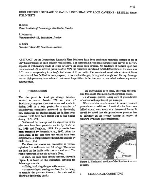
-<strong>the</strong> surrounding rock mass, absorbing <strong>the</strong> pressure<br />
forces <strong>and</strong> thus acting as <strong>the</strong> pressure vessel.<br />
The pilot plant for lined gas storage facilities, -a drainage system, taking care <strong>of</strong> groundwater<br />
located in central Sweden 250 km west <strong>of</strong> inflow as well as potential gas leakages.<br />
Stockholm, comprises three test rooms <strong>and</strong> was built Water curtains have been used to ensure constant<br />
during 1988 as a joint project by a number <strong>of</strong> groundwater conditions. 15 vertical holes have been<br />
Sc<strong>and</strong>inavian companies interested in developing drilled around each room at a distance <strong>of</strong> 2-4 In- It<br />
new techniques for storing natural gas in lined rock should be noted that <strong>the</strong> groundwater pressure has<br />
caverns. Tests have been carried out in four phases no influence on <strong>the</strong> storage concept in respect <strong>of</strong><br />
during 1989-1993.<br />
Outlines <strong>of</strong> <strong>the</strong> concept <strong>and</strong> <strong>the</strong> objectives <strong>of</strong> <strong>the</strong><br />
pilot tests have been presented earlier by Lindbo et<br />
al., 1989 <strong>and</strong> Tengborg, 1989. Early results have<br />
been presented by Rosendal et al., 1992. After <strong>the</strong><br />
completion <strong>of</strong> <strong>the</strong> field tests <strong>the</strong> results have been<br />
subjected to a comprehensive <strong>the</strong>oretical analysis by<br />
Stille et al., 1994.<br />
The three test rooms are excavated as vertical<br />
cylinders 5 m in diameter <strong>and</strong> 10m high. The rooms<br />
are lined on <strong>the</strong> inside with concrete <strong>and</strong> steel. The<br />
rock overburden above <strong>the</strong> rooms is 50 m.<br />
In short, <strong>the</strong> lined rock cavern concept, shown in<br />
pressure levels <strong>and</strong> gas containment.<br />
Figure 1, is based on <strong>the</strong> interaction between <strong>the</strong><br />
following elements:<br />
-a lining, enclosing <strong>the</strong> gas in <strong>the</strong> cavern<br />
-a concrete layer, serving as a base for <strong>the</strong> lining,<br />
Figure 1. Horizontal section <strong>of</strong> <strong>the</strong> lined rock cavern<br />
concept.<br />
to transfer <strong>the</strong> pressure forces to <strong>the</strong> rock <strong>and</strong> to<br />
distribute developing cracks<br />
2<br />
GEOLOGICAL CONDITIONS