Technical Review of the Lined Rock Cavern Concept and Design ...
Technical Review of the Lined Rock Cavern Concept and Design ...
Technical Review of the Lined Rock Cavern Concept and Design ...

You also want an ePaper? Increase the reach of your titles
YUMPU automatically turns print PDFs into web optimized ePapers that Google loves.
cracks have developed despite a tangential strain by<br />
far exceeding 0.02% (0.1% strain measured).<br />
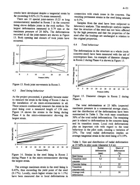
There are 10 special joint-meters (0.25 m long<br />
extenso meters) installed in Room 3 in <strong>the</strong> concrete<br />
lining above definite joints in <strong>the</strong> rock surface. The<br />
largest deformation measured is 0.79 mm at <strong>the</strong><br />
maximum pressure <strong>of</strong> 28 rvIPa. The deformations<br />
recorded in all <strong>the</strong> joint-meters are shown in Figure<br />
13. Both opening <strong>and</strong> closure <strong>of</strong> rock joints have<br />
occun-ed.<br />
1,0<br />
e ,§. 0,5<br />
.§<br />
~<br />
.g<br />
~ 0,0<br />
~,5<br />
0 5 10 15<br />
~ (MPa)<br />
1 '/<br />
20 25 30<br />
Figure 13. <strong>Rock</strong> joint movements in Room 3.<br />
4.3 Steel lining behaviour<br />
As <strong>the</strong> project proceeded, it gradually became easier<br />
to measure <strong>the</strong> strain in <strong>the</strong> lining <strong>of</strong> Room 2 due to<br />
<strong>the</strong> installation <strong>of</strong> six micro-extensometers in all.<br />
These sensors continuously measure <strong>the</strong> strain in <strong>the</strong><br />
steel lining over a measured length <strong>of</strong> 150 mm.<br />
Figure 14 shows <strong>the</strong> strains in <strong>the</strong> lining during<br />
Phase 4 in <strong>the</strong> micro-extensometer showing <strong>the</strong><br />
largest strain.<br />
15 20 25 30 35 40 45 50 55<br />
Pressure (MPa)<br />
Figure 14. Strains in <strong>the</strong> steel lining in Room 2<br />
during Phase 4 in <strong>the</strong> micro-extensometer showing<br />
<strong>the</strong> largest strain.<br />
The average maximum strain in <strong>the</strong> steel lining is<br />
0.45%, thus exceeding <strong>the</strong> yield point <strong>of</strong> <strong>the</strong> steel<br />
(0.17%). Locally, much higher strains (up to 1.1%)<br />
have been measured due to local deformations in<br />
A-21<br />
connection with crack zones in <strong>the</strong> concrete. The<br />
resulting pennanent strains in <strong>the</strong> steel lining amount<br />
to 0.5%.<br />
Samples from <strong>the</strong> steel have been subjected to<br />
laboratory analysis. This metallurgic analysis implies<br />
that <strong>the</strong> structure <strong>of</strong> ,ilie steel has not been affected<br />
by <strong>the</strong> high pressures <strong>and</strong> that <strong>the</strong> properties <strong>of</strong> <strong>the</strong><br />
steel after <strong>the</strong> loadings are unchanged in relation to<br />
<strong>the</strong> original properties.<br />
4.4 Total behaviour<br />
The deformations in <strong>the</strong> structure as a whole (rockconcrete-steel)<br />
have been measured with <strong>the</strong> aid <strong>of</strong><br />
convergence lines. An example <strong>of</strong> diameter changes<br />
in Room 2 during Phase 4 is shown in Figure 15.<br />
0 5 10 15 20 25 30 35 40 45 50 55<br />
Pressure (MPa)<br />
Figure 15. Diameter changes in Room 2 during<br />
Phase 4.<br />
The total deformations at 25 MPa (expected<br />
maximum pressure in a commercial storage plant),<br />
<strong>and</strong> <strong>the</strong> distn"bution <strong>of</strong> <strong>the</strong> defonnations have been<br />
SllmmSirised in Table 3. The rock mass contn"butes<br />
50% <strong>of</strong> <strong>the</strong> total radial deformations. The remaining<br />
part is related to defonnations in <strong>the</strong> concrete lining<br />
<strong>and</strong> its transition zones. Local rock deformations<br />
play an important role with regard to <strong>the</strong> total<br />
behaviour in <strong>the</strong> pilot scale, causing a variation <strong>of</strong><br />
25%. The total radial deformation implies an<br />
average tangential strain in <strong>the</strong> steel lining <strong>of</strong> 0.18%.<br />
Table 3. Size <strong>and</strong> distnoution <strong>of</strong> radial deformation<br />
at 25 MPa in pilot scale (diameter 4.4 m).