GEA Air Handling Units - GEA Air Treatment
GEA Air Handling Units - GEA Air Treatment
GEA Air Handling Units - GEA Air Treatment

Create successful ePaper yourself
Turn your PDF publications into a flip-book with our unique Google optimized e-Paper software.
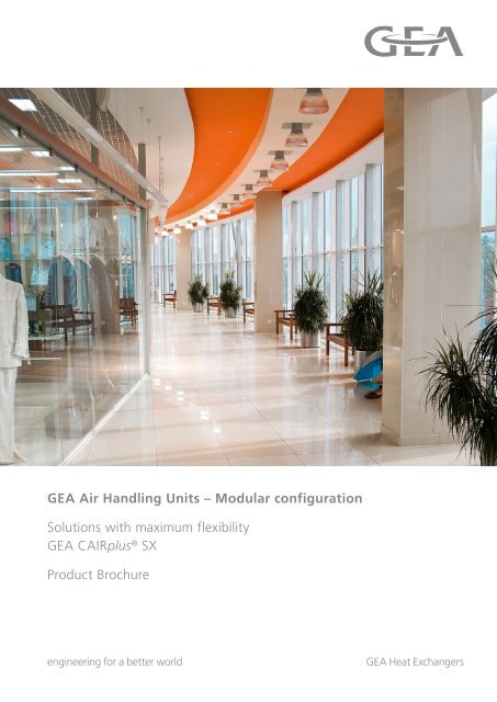
<strong>GEA</strong> <strong>Air</strong> <strong>Handling</strong> <strong>Units</strong> – Modular configuration<br />
Solutions with maximum flexibility<br />
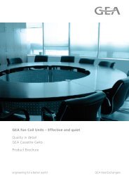
<strong>GEA</strong> CAIRplus ® SX<br />
Product Brochure<br />
engineering for a better world <strong>GEA</strong> Heat Exchangers
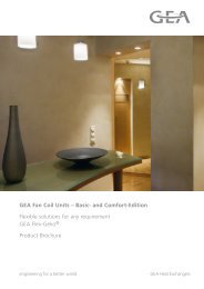
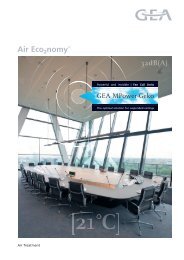
Overview of <strong>GEA</strong> <strong>Air</strong> <strong>Handling</strong> <strong>Units</strong><br />
<strong>GEA</strong> <strong>Air</strong> <strong>Handling</strong> <strong>Units</strong><br />
Optimized for any application<br />
<strong>Air</strong> flow Type of unit<br />
(m 3 /h) Modular units Compact units<br />
100,000<br />
50,000<br />
10,000<br />
1,000<br />
0<br />
CAIRplus<br />
CAIRfricostar<br />
ATpicco<br />
Modular<br />
Customized configurations possible<br />
by modular configuration of the units<br />
COM4<br />
Fricostar Micro<br />
Compact<br />
Pre-configured and optimized HVAC<br />
systems, ready for connection, with<br />
integrated control systems and<br />
high-efficiency energy recuperation<br />
CAIRplus<br />
High-end range of units with<br />
maximum flexibility (model sizes,<br />
enclosure versions, components,<br />
configurations, etc.)<br />
CAIRfricostar<br />
Optimized solution for climate<br />
control of indoor swimming pools<br />
and wellness areas<br />
ATpicco<br />
Full-capacity air-handling unit with<br />
flat design for installation above a<br />
suspended ceiling<br />
COM4<br />
Compact universal system solution<br />
for many and various application<br />
areas<br />
Fricostar Micro<br />
Space-saving units for climate control<br />
of relatively small indoor swimming<br />
pools (also for retrofit)<br />
Project requirements never exactly repeat themselves: with its especially designed product ranges, <strong>GEA</strong> <strong>Air</strong> <strong>Treatment</strong> can satisfy all expectations.<br />
For some applications, only the exchange of air is required; for others, however, there are more sophisticated requirements with respect to<br />
temperature, humidity, and air purity. Modular units allow free selection of components and functions and can be matched to their requirements<br />
down to the smallest detail. Compact units are optimized to their applications, with high-efficiency energy recuperation. They are delivered ready<br />
for connection, with integrated control systems.<br />
[2] PR-2009-0038-GB · Subject to modification · K4-10/2012
<strong>GEA</strong> CAIRplus SX<br />
With modular configuration – and with<br />
virtually unlimited possibilities<br />
When room air lies within the narrow range of optimal indoor<br />
comfort temperatures, we feel comfortable. This applies<br />
not only for home applications, but also for production, office,<br />
and sales rooms.<br />
Indoor room climate is influenced by many factors: the number<br />
of persons in a room, the number of computers, the lighting, and<br />
many more. This is why central air handling is so important for<br />
closed rooms. But climate also plays an essential role in production<br />
processes. Good HVAC conditions must prevail, for example,<br />
in the food and beverage industry. In hospitals and in the pharmaceutical<br />
industry, hygiene furthermore plays a critical role.<br />
<strong>GEA</strong> central air handling units implement heating, cooling, humidifying<br />
and dehumidifying, filtration, and cost-effective energy<br />
recuperation. And <strong>GEA</strong> <strong>Air</strong> <strong>Treatment</strong> is constantly working<br />
to improve the quality and engineering of these functions.<br />
One result here is the new generation of central air handling<br />
units: <strong>GEA</strong> CAIRplus.<br />
For use both in new buildings and in the modernization of existing<br />
facilities, <strong>GEA</strong> CAIRplus allows optimal planning and design<br />
of central HVAC solutions. The various models can be flexibly<br />
selected and matched to any requirements, and are<br />
dimensioned by means of <strong>GEA</strong> planning software. At <strong>GEA</strong> <strong>Air</strong><br />
<strong>Treatment</strong>, quality and innovative technology stand in the foreground<br />
of these efforts: ensured by constant inspection, further<br />
development, and maintenance of production processes at the<br />
state of the art.<br />
The greatest share of the costs of a central air handling unit arises<br />
from its operating expenses spread over its entire service life<br />
– and not from the original acquisition price. As a result, <strong>GEA</strong><br />
CAIRplus units can be economically outfitted with high-efficiency<br />
energy recuperation and with energy-saving drive systems.<br />
CAIRplus already now conforms to the EU directive that goes<br />
into effect in mid-2011 and that stipulates the use of electric motors<br />
from efficiency class IE2/EFF1. CAIRplus is furthermore certified<br />
according to Eurovent and the German Association of HVAC<br />
Manufacturers, which assures greater transparency and safety.<br />
In addition, completely smooth inner surfaces and good access<br />
to all components guarantee high hygienic standards. <strong>GEA</strong> regularly<br />
monitors the currently valid official regulations and assures<br />
that they are being met by <strong>GEA</strong> CAIRplus.<br />
PR-2009-0038-GB · Subject to modification · K4-10/2012<br />
Choice of model configurations<br />
All model configurations are available for <strong>GEA</strong><br />
CAIRplus: indoor and outdoor versions, vertical or<br />
horizontal installation – as well as configurations<br />
with units on top of each other, behind each other, or<br />
next to each other.<br />
Simple installation and maintenance<br />
In addition to space for their installed components,<br />
<strong>GEA</strong> CAIRplus units also provide extra installation<br />
space for piping and cabling. Large service hatches<br />
additionally make it significantly easier to maintain<br />
and service the units.<br />
All hatch locks, threaded connections, and hinges are<br />
integrated into the unit frame. Even partition joints<br />
do not require any additional length of the units. As<br />
required, individual components can be simply<br />
installed on the installation site from the outside.<br />
The lifting lugs in the top profile section of the units<br />
make it simple and easy to transport them to the<br />
installation site (for units delivered up to 1,500 kg).<br />
[3]
Eurovent and the German Association of HVAC Manufacturers<br />
Tested + certified = maximum safety<br />
HVAC systems by <strong>GEA</strong> <strong>Air</strong> <strong>Treatment</strong> satisfy the most stringent<br />
of quality requirements and are subjected to periodic<br />
testing.<br />
Measuring means acquisition of knowledge. And the custom<br />
ers get exactly what they expect. This is the motto of the Eu<br />
rovent Certification Program. As a result, documentation and<br />
software are subjected to strict tests.<br />
Directives EN 13053 and EN 1886 stipulate the criteria to be ap-<br />
plied in these tests. Independent testing institutions periodi-<br />
cally inspect these characteristics in accordance with Eurovent<br />
certification stipulations.<br />
Modelbox Test – enclosure properties in accordance with EN 1886<br />
Enclosures are provided to an independent testing institution<br />
every 6 years, which tests these enclosures in accordance with<br />
the following properties.<br />
Mechanical stability (D1 … D3)<br />
Enclosure leakage (L1 … L3)<br />
Filter-bypass leakage (G1 … F9)<br />
Thermal insulation (T1 … T5)<br />
Thermal-bridge factor (TB1 … TB5)<br />
Sound insulation of the enclosure.<br />
Real Unit Test – software performance characteristics as per<br />
EN 13053<br />
In these tests, an independent expert selects one unit type every 3<br />
years at the manufacturer’s plant. This type is then exactly manufactured<br />
as a specimen copy, measured by a testing institute, and<br />
compared to the software data. The manufacturer’s software is then<br />
certified only if all the performance characteristics of the copy are<br />
successfully verified. The following performance data are tested:<br />
Mechanical stability<br />
Enclosure leakage<br />
Filter-bypass leakage<br />
<strong>Air</strong> flow rate<br />
Available static pressure<br />
Power consumption<br />
Noise emitted from the enclosure<br />
Noise transmitted by the air flow<br />
Heating capacity<br />
Cooing capacity<br />
Energy recuperation efficiency<br />
Pressure loss on the water side<br />
[4] PR-2009-0038-GB · Subject to modification · K4-10/2012
Inspection of the production plants<br />
Once every year, an expert visits the production plant of the cer-<br />
tified manufacturer. This inspection checks conformity of the<br />
manufactured units with the design software.<br />
Tested efficiency – certification of energy characteristics<br />
Consumption by HVAC systems represents a major share of the<br />
energy used by buildings. To reduce this consumption and, in<br />
turn, CO2 emissions, measures are being taken in many coun-<br />
tries to increase the efficiency of HVAC systems. But how it is<br />
possible to objectively assess energy efficiency on the basis of<br />
simple characteristic values? Numerous factors influence the en-<br />
ergy consumption of a central air-handling unit:<br />
The air speed in the unit<br />
The power consumption of the motors<br />
The efficiency and the pressure drop of the energy<br />
recuperation<br />
Climate conditions at the installation site.<br />
The Eurovent energy label<br />
Analysis of these factors is summarized in Eurovent efficiency<br />
classes A to
46 %<br />
Fan energy costs<br />
15 %<br />
Investments<br />
10 %<br />
Maintenance<br />
2 %<br />
Pump energy costs<br />
27 %<br />
Energy costs<br />
for heating, cooling, humidifying<br />
Life-cycle cost calculation<br />
Consideration of all costs in advance<br />
Example of an office building<br />
Calculations performed by <strong>GEA</strong> Lplus software (see page 7)<br />
are based on Eurovent recommendations for determination<br />
of life-cycle costs, and likewise take into account important<br />
standards and regulatory frameworks (such as DIN V18599-3<br />
and VDI 2067-1).<br />
Life Cycle Costs<br />
Investment costs<br />
Planning<br />
Initial acquisition<br />
Installation<br />
Energy costs<br />
Electric power<br />
Heating and cooling<br />
Water<br />
Energy labels provide the basis of assessing the energy qual<br />
ity of an HVAC unit by a simple rating number. For exact state<br />
ments on the expected operating costs, however, it is neces<br />
sary to calculate the lifecycle costs (LCC).<br />
LCC Guidelines for <strong>Air</strong> <strong>Handling</strong> <strong>Units</strong> provide the basis for this<br />
calculation. These guidelines are provided in accordance with<br />
DIN V18599-3 and VDI 2067-1. Calculation in turn takes place<br />
in accordance with climate conditions at the equipment site, as<br />
well as with operating times. Building behavior is simulated by<br />
scenarios that select the supply and exhaust-air temperatures as<br />
a function of outdoor-air conditions. Further influencing varia-<br />
bles such as energy prices, investment costs, and costs for main-<br />
tenance and servicing round out the basis for calculation.<br />
Several equipment configurations can be calculated in parallel<br />
and can be compared to each other. The result is a presentation<br />
that – in addition to costs of the individual energy media – also<br />
indicates the total costs accruing throughout the life cycle being<br />
considered.<br />
Maintenance<br />
Cleaning and maintenance<br />
Repair<br />
Disposal<br />
Disassembly<br />
Recycling and disposal<br />
[6] PR-2009-0038-GB · Subject to modification · K4-10/2012
<strong>GEA</strong> Lplus design software<br />
For fast and reliable engineering design<br />
<strong>GEA</strong> CAIRplus central air handling units are characterized by<br />
their great diversity of models, which provide a tailored solu<br />
tion for each requirement being presented, and for every build<br />
ing situation. Each unit is individually designed with the <strong>GEA</strong><br />
Lplus design software.<br />
Time is money: and this especially applies to the project engi-<br />
neering of HVAC facilities. We have developed the <strong>GEA</strong> Lplus<br />
design software to make your selection and configuration as fast<br />
and as simple as possible for a precision climate-control system<br />
that is optimal for your needs.<br />
<strong>GEA</strong> CAIRplus precision climate-control systems have the ad-<br />
vantage that all products can be designed to meet individual re-<br />
quirements. The <strong>GEA</strong> Lplus design software helps you to imple-<br />
ment your desired system at the turn of a hand. The system<br />
makes configuration proposals in accordance with your entry of<br />
information. Lplus immediately calculates and outputs unit subdivisions,<br />
configuration of the modules, as well as dimensions<br />
and weights. Believe us: there is no way for faster and more reliable<br />
planning. And you will gain valuable time for other tasks.<br />
PR-2009-0038-GB · Subject to modification · K4-10/2012<br />
Benefits of using <strong>GEA</strong> Lplus design software<br />
Individual configuration proposals<br />
Determination and display of unit sub-divisions,<br />
modular configurations, dimensions, and weights<br />
Calculation of life-cycle costs (LCC)<br />
Simple program handling<br />
Fast, reliable selections and planning<br />
Valuable time gain for other tasks<br />
Indication of energy-efficiency classes (Eurovent<br />
and German Association of HVAC Manufacturers)<br />
Regular monitoring by Eurovent of the validity of<br />
the calculation procedure<br />
<strong>GEA</strong> Lplus design software covers all products by <strong>GEA</strong> <strong>Air</strong><br />
<strong>Treatment</strong>. The free full version can be downloaded under<br />
www.gea-airtreatment.com under the menu link Media/<br />
Download/Lplus. Or, it can be ordered from us.<br />
[7]
Hygiene connection frame<br />
Assurance of high hygiene standards<br />
Hygiene-tested HVAC systems<br />
The enclosures of <strong>GEA</strong> CAIRplus units are completely smooth<br />
on the inside, which makes them easy to keep clean. This<br />
assures optimal conditions for hygienic operations in<br />
accordance with VDI 6022, VDI 3803, and DIN 1946 Part 4.<br />
In the design and structural engineering of <strong>GEA</strong> CAIRplus<br />
central air handling systems, great emphasis has been placed<br />
on equipment design that assures conformity with high hy<br />
giene standards.<br />
<strong>GEA</strong> CAIRplus units are entirely smooth on the inside. There<br />
are no edges or threaded connections to restrict complete clean-<br />
ing of the unit.<br />
For stricter hygiene standards – for example, in buildings and<br />
rooms of public health institutions – additional requirements<br />
must be satisfied as described in DIN 1946, Part 4. <strong>GEA</strong> CAIRplus<br />
central air handling systems satisfy these requirements as well.<br />
Hygiene requirements applicable to HVAC equipment are stipulated<br />
in the following standards and guidelines:<br />
VDI 6022 Sheet 1<br />
Hygiene requirements placed on HVAC systems and units<br />
EN 1886<br />
Mechanical properties and measurement techniques<br />
EN 13053<br />
Performance indicators<br />
DIN EN 13779<br />
General fundamentals and requirements<br />
DIN 1946 Part 4<br />
HVAC systems in hospitals<br />
Institute for<br />
<strong>Air</strong> Hygiene<br />
tested by<br />
Hygiene-relevant standards<br />
[8] PR-2009-0038-GB · Subject to modification · K4-10/2012
<strong>GEA</strong> CAIRplus central air handling units with integrated cool<br />
ing systems are virtually entirely ready for connection, and<br />
their components have been optimally coordinated with each<br />
other. They have proved highly attractive as a result of their<br />
integrated control technology and highly efficient energy re<br />
cuperation.<br />
DX direct evaporator technology with R134a refrigerant achieves<br />
high levels of reliability and long service life. These systems are<br />
also absolutely reliable in service, even under conditions of high<br />
outdoor temperatures. Their output can be continuously matched<br />
to momentary cooling requirements. For minimized energy con-<br />
sumption, <strong>GEA</strong> also offers the option here of adiabatic evapora-<br />
tive cooling. All cooling components and the control system have<br />
been integrated in the unit.<br />
The cooling circulation system<br />
R134a as refrigerant<br />
Heat exchanger as direct evaporator and refrigerant<br />
condenser<br />
Semi-hermetic compressor (reciprocating piston compressor<br />
up to 100 kW cooling capacity, with screw compressor for<br />
greater requirements)<br />
Output control by means of cylinder shut-off and frequency<br />
converter<br />
Control range from 30 to 100 % of the maximum cooling<br />
capacity (optional: 10 to 100 %)<br />
The refrigerant R134a<br />
Good thermal and energy characteristics<br />
No temperature glide<br />
Low condensation pressure; high condensation tempera-<br />
tures > 60 °C are possible<br />
Reliable heat dissipation as a result of great temperature<br />
range<br />
Quiet operation; great operational reliability<br />
Low energy consumption<br />
Low global warming potential (GWP)<br />
No ozone depletion potential<br />
The control system<br />
Control cabinet integrated into the unit and completely wired<br />
Control by the <strong>GEA</strong> Matrix 4700 system<br />
Optional bus interface<br />
Everything from one source<br />
Integrated cooling<br />
As alternative, available in an external control cabinet<br />
PR-2009-0038-GB · Subject to modification · K4-10/2012<br />
Overview of the integrated cooling technology imple<br />
mented here<br />
Great number and variety of application areas: e.g.,<br />
in offices, supermarkets, and department stores<br />
Small footprint<br />
Everything from one supplier<br />
No external piping<br />
Little engineering effort<br />
Simple installation<br />
Great energy efficiency, since the system is always<br />
connected to energy recuperation<br />
For air flow from 3,000 to 50,000 m³/h<br />
For indoor and outdoor installation<br />
Optional adiabatic exhaust-air humidification<br />
Control by the <strong>GEA</strong> MATRIX 4700<br />
Project-specific solutions possible<br />
[9]
Safety in explosion-endangered areas<br />
<strong>Air</strong> handling conformity with ATEX<br />
Explosion groups<br />
Classification of the amount of<br />
energy required to ignite substancedependent<br />
quantities and volumes:<br />
IIA = a great amount of energy<br />
IIB = a moderate amount of<br />
energy<br />
IIC = a small amount of energy<br />
Classification into zones<br />
With its products for numerous applications, <strong>GEA</strong> <strong>Air</strong> Treat<br />
ment offers the necessary safety for explosionendangered ar<br />
eas. <strong>GEA</strong> central air handling units represent a significant el<br />
ement here. Their many and various functions provide the<br />
basis of fully functional HVAC systems for application in ex<br />
plosionendangered zones.<br />
An atmosphere can be explosive as a result of local conditions<br />
and/or operational circumstances. Such specific conditions in-<br />
volve mixtures of air and combustible gas, vapor, mist, or dust.<br />
For an explosion of these substances, atmospheric conditions are<br />
necessary under which the process of combustion – after suc-<br />
cessful ignition – spreads to the entire uncombusted mixture.<br />
Explosion-endangered areas can develop where explosive gases,<br />
mist, vapor, or dust exist or could form. Areas in which danger-<br />
ous and explosive atmospheres can occur are classified into<br />
zones, in accordance with the probability of development of such<br />
an explosive atmosphere.<br />
Danger of explosion Example Gas Dust Required category<br />
An explosive atmosphere prevails In the inside of containers Zone 0 Zone 20 1<br />
continuously, frequently, or for long periods<br />
An explosive atmosphere occasionally The area around filling and Zone 1 Zone 21 2<br />
prevails emptying openings<br />
An explosive atmosphere rarely prevails, Areas around Zones 1 / 21 Zone 2 Zone 22 3<br />
and then only for short periods of time<br />
Breakdown into temperature classes<br />
Temperature class T1 T2 T3 T4 T5 T6<br />
Ignition temperature of the combustible substances greater than ºC 450 300 200 135 100 85<br />
Maximum permissible surface temperature of equipment ºC 450 300 200 135 100 85<br />
[10] PR-2009-0038-GB · Subject to modification · K4-10/2012
All operators of facilities with the possibility of formation of ex-<br />
plosive atmospheres are required to classify their plants by zone:<br />
either themselves, or with the aid of a consulting company, in<br />
accordance with ATEX 137 (Guideline 1999/92/EG) and its na-<br />
tional laws and ordnances.<br />
The operator must also observe the fundamental measures for<br />
primary protection against explosions with “avoidance of explo-<br />
sive atmospheres”: e.g., by means of dilution, limiting, substitu-<br />
tion of substances, or the like.<br />
A ventilation or climate-control unit as individual component<br />
cannot alone guarantee complete and comprehensive explosion<br />
protection, since the protective concept must cover the entire fa-<br />
cility. The overall responsibility therefore finally lies with the<br />
user or the plant builder.<br />
ATEX conformity certification of <strong>GEA</strong> <strong>Air</strong> <strong>Treatment</strong><br />
Guideline 94/9/EG – better known as ATEX 95 – contains the<br />
stipulations for “equipment and protective systems for applica-<br />
tion in explosion-endangered areas in conformity with the rele-<br />
vant stipulations.” <strong>GEA</strong> <strong>Air</strong> <strong>Treatment</strong> delivers <strong>GEA</strong> CAIRplus<br />
for use in explosion-endangered areas in accordance and con-<br />
formity with ATEX Guideline 94/9/EG (ATEX 95).<br />
ATEX Conformity Certification has been provided for the follow-<br />
ing applications:<br />
ATEX Conformity Certification<br />
for <strong>GEA</strong> <strong>Air</strong> <strong>Treatment</strong><br />
Explosive gas applications Explosive dust applications<br />
II 3 G IIB T3 Inside II 3 D T200 ºC Inside<br />
II 3 G IIB T4 Inside II 2 D T200 ºC Inside<br />
II 2 G IIB T3<br />
II 2 G IIB T4<br />
PR-2009-0038-GB · Subject to modification · K4-10/2012<br />
Equipment classification in accordance with ATEX<br />
Example: Ex II 3 G IIB T4 Inside Equipment<br />
II<br />
Equipment Group (I = mining; II = all other areas of<br />
application)<br />
3<br />
Category (3 for Zones 2, 22; 2 for Zones 1, 2, 21, 22;<br />
1 for all zones)<br />
G<br />
G = gas; D = dust<br />
IIB<br />
Explosion Group<br />
T4<br />
Temperature class<br />
Inside<br />
Inside the equipment (if no indication given, then for<br />
inside and outside)<br />
[11]
The control system: efficient and intelligent<br />
The right turn for the right climate<br />
<strong>GEA</strong> MATRIX 4700 Compact System Control<br />
Control system with numerous monitoring<br />
possibilities:<br />
Differential pressure measurement for monitoring<br />
of the supply and exhaust-air filter<br />
Position measurement of the outdoor-air louver<br />
to avoid frost damage<br />
Temperature measurement for avoiding frost,<br />
with additional frost-protection thermostat to<br />
provide switch-off<br />
Icing temperature measurement to protect the<br />
direct evaporator<br />
Monitoring of the safety chain for external<br />
compressor-condenser units<br />
Plausibility check for detection of sensor faults<br />
Monitoring of malfunction reports from<br />
circulation pumps, frequency converters, and<br />
energy-recuperation systems<br />
<strong>GEA</strong> DDC cabinet for open- and closed-loop control<br />
With both <strong>GEA</strong> MATRIX Compact System Control, or with<br />
<strong>GEA</strong> DDC System Control: the user enjoys many functionalities<br />
for operation and control of the <strong>GEA</strong> CAIRplus.<br />
The user can optimally match the functions of the central air handling<br />
unit to the respective application case: either by means of<br />
the MATRIX operator-control unit, or by the <strong>GEA</strong> MATRIX.PC<br />
startup software. The system acquires a great number of measured<br />
values and continuously monitors them, to assure safe and<br />
reliable operation of the <strong>GEA</strong> CAIRplus, with a minimum of difficulties.<br />
If one of the monitoring systems responds, this is reported<br />
in plain text by the operator-control unit, and in parallel<br />
via the malfunction-report output and/or via the interface to the<br />
building-services management system.<br />
Communicative and understandable –<br />
the operator-control level<br />
The MATRIX operator-control unit has a graphics-capable display<br />
that is operated with a menu structure analogous to that of<br />
a mobile telephone. As a result, setpoint values and switching<br />
times can be very easily entered, and current actual values and<br />
instruction messages can be simply read off. If a second operator-control<br />
unit is desired (e.g., for advance, simple entry of setpoint<br />
temperatures), this can take place via the existing <strong>GEA</strong> MA-<br />
TRIX.Net bus system.<br />
Fast initial startup of the system<br />
Before being delivered, the components of the <strong>GEA</strong> MATRIX<br />
Compact System Control are completely tested for their functions,<br />
with advance setting of as many functionalities as possible.<br />
<strong>GEA</strong> MATRIX 4700 Compact System Control or <strong>GEA</strong><br />
DDC System Control<br />
The <strong>GEA</strong> MATRIX Compact System Control allows open- and<br />
closed-loop control of all components of <strong>GEA</strong> CAIRplus central<br />
air handling systems for partial climate control. An exception<br />
here is compete climate control via a humidifying and dehumidifying<br />
section. For this purpose, <strong>GEA</strong> offers a DDC system control<br />
with no restrictions in functionalities. It is configured with<br />
customizing to satisfy all details of the building-owner’s requirement<br />
catalog.<br />
MATRIX 4700 – maximum motor ratings<br />
with frequency converters: 2 x 15.0 kW<br />
without frequency converters: 2 x 7.5 kW<br />
[12] PR-2009-0038-GB · Subject to modification · K4-10/2012
<strong>GEA</strong> MATRIX 4700 Compact closed-loop system control<br />
Exhaust air<br />
Outside air<br />
FU<br />
� �<br />
1<br />
<strong>GEA</strong> Cairplus<br />
M<br />
AD<br />
5<br />
6<br />
∆p<br />
2 3<br />
JK FA ER<br />
Injection<br />
circuit<br />
(frost protection)<br />
ER SR<br />
9<br />
M<br />
∆p ∆p<br />
25<br />
20<br />
25<br />
4<br />
HW KW<br />
M<br />
M<br />
A<br />
AB<br />
B<br />
A<br />
B<br />
AB<br />
FA<br />
3<br />
FU<br />
6<br />
5<br />
ZD<br />
Distribution<br />
control<br />
Components and functions <strong>GEA</strong> scope of delivery or activation control<br />
26<br />
21<br />
∆p<br />
M<br />
JK<br />
2<br />
8 8<br />
�<br />
�<br />
7<br />
Extracted air<br />
Supply air<br />
ZD Supply-air fan with frequency converter FU installed Direct drive 3~400 Volt / 50 Hz<br />
AD <strong>Air</strong>-extraction fan with frequency converter FU installed Direct drive 3~400 Volt / 50 Hz<br />
JK Shutter flaps outside air / extracted air installed Counter-action shutters with gear drive<br />
FA Filter for outside air / extracted air installed Outside air F7 / Extracted air F5<br />
ER Energy recovery ECOROT <strong>GEA</strong> rotation heat exchanger<br />
HW Heating (low-pressure hot water, LPHW) no steam Heating with steam upon request<br />
KW Cooling (pumped chilled water, PCW) No refrigerant Cooling with refrigerant upon request<br />
SR Compact open- and closed-loop control cabinet installed Completely wired for operation<br />
1 Outside sensor separate <strong>GEA</strong> NTC sensor with IP54 housing<br />
2 Servomotors for shutter flaps (outside air/extracted air) installed <strong>GEA</strong> motor drive 230 Volt<br />
3 Pressure-drop switch (outside air/extracted air) installed Lower response sensitivity = 40 Pa<br />
4 Frost-protection thermostat installed <strong>GEA</strong> thermostat with change-over contact<br />
5 Pressure sensors for air-volume flow control installed Volume or pressure or signal, external 0 ... 10 Volt<br />
6 Frequency converter (supply air/extracted air) installed For speed control of fan motor<br />
7 Supply-air minimal-limitation sensor installed <strong>GEA</strong> NTC installed sensor<br />
8 Extracted-air sensor, installed, &/or sep. room sensor installed / separate <strong>GEA</strong> NTC installed sensor or with IP21 housing<br />
9 Drive motor for rotation heat exchanger installed For speed control of rotor<br />
20 Servomotor, 3-way mixing valve (LPHW heating) separate <strong>GEA</strong> motor drive 230 Volt<br />
21 Servomotor 3-way distribution valve (PCW cooling) separate <strong>GEA</strong> motor drive 230 Volt<br />
Stellmotor 3-way valves Hydraulics<br />
StellmoAB Return flow from heat exchanger Partial medium volume Medium: water or brine<br />
StellmoBB Bypass from supply line Partial medium volume Medium: water or brine<br />
StellmoAB Return flow line to energy producer Total medium volume Medium: water or brine<br />
25 Throttle valve (mechanical) from customer For customer-side hydraulic adjustment<br />
26 Secondary pump for heating cycle from customer <strong>GEA</strong> activation control ON / OFF<br />
PR-2009-0038-GB · Subject to modification · K4-10/2012<br />
�<br />
room<br />
[13]
Examples of application possibilities <strong>GEA</strong> MATRIX 4700 compact closed-loop system control<br />
<strong>GEA</strong> CAIRplus with V-belt drive, without energy recuperation, mixed-air operation<br />
Partial climate control = without humidification<br />
Filtration - supply air - cooling - heating - filtration - outside air / / exhaust air - recirculated air - extracted air<br />
Supply<br />
air<br />
<strong>GEA</strong> CAIRplus with direct drive, without energy recuperation, mixed-air operation<br />
Partial climate control = without humidification<br />
<strong>GEA</strong> CAIRplus with direct drive and ECOPLAT energy recuperation, mixed-air operation<br />
Partial climate control = without humidification<br />
Supply air - cooling - heating - recirculated air - ECOPLAT - filtration - outside air // filtration - extracted air - recirculated air - ECOPLAT - exhaust air<br />
Supply<br />
air<br />
<strong>GEA</strong> CAIRplus with direct drive and ECOROT energy recuperation, mixed-air operation<br />
Partial climate control = without humidification<br />
Supply air - cooling - heating - recirculated air - ECOROT - filtration - outside air // filtration - extracted air - recirculated air - ECOROT - exhaust air<br />
Supply<br />
air<br />
Extracted air<br />
Extracted air<br />
Outside air Exhaust air<br />
Supply air - cooling - heating - filtration - outside air / / exhaust air - recirculated air - extracted air<br />
Supply<br />
air<br />
Outside air Exhaust air<br />
Exhaust air<br />
Extracted<br />
air<br />
Extracted<br />
air<br />
Outside<br />
air<br />
Exhaust<br />
air<br />
Outside<br />
air<br />
Activation control of the valve drives as desired: with or without mounted or separate frequency converters.<br />
[14] PR-2009-0038-GB · Subject to modification · K4-10/2012
<strong>GEA</strong> DDC closed-loop system control Examples of application possibilities<br />
<strong>GEA</strong> CAIRplus with V-belt drive, without energy recuperation, with humidification and dehumidification, 100 % outside-air operation<br />
Full climate control = with humidification and dehumidification<br />
Filtration - supply air - dehumidification - humidification - cooling - heating - filtration - outside air or recirculated air<br />
Supply<br />
air<br />
Activation control of the valve drives as desired: with or without mounted or separate frequency converters.<br />
PR-2009-0038-GB · Subject to modification · K4-10/2012<br />
Outside<br />
air<br />
<strong>GEA</strong> CAIRplus with V-belt drive, without energy recuperation, with humidification and dehumidification, mixed-air operation<br />
Full climate control = with humidification and dehumidification<br />
Filtration - supply air - dehumidification - humidification - cooling - heating - filtration - outside air // exhaust air - recirculated air - extracted air<br />
Supply<br />
air<br />
Outside air Exhaust air<br />
<strong>GEA</strong> CAIRplus with direct drive, without energy recuperation, with humidification and dehumidification, 100 % outside-air operation<br />
Full climate control = with humidification and dehumidification<br />
Supply air - dehumidification - humidification - cooling - heating - filtration - outside air or recirculated air<br />
Supply<br />
air<br />
Extracted<br />
air<br />
Outside<br />
air<br />
<strong>GEA</strong> CAIRplus with direct drive, without energy recuperation, with humidification and dehumidification, mixed-air operation<br />
Full climate control = with humidification and dehumidification<br />
Supply air - dehumidification - humidification - cooling - heating - filtration - outside air // exhaust air - recirculated air - extracted air<br />
Supply<br />
air<br />
Outside air Exhaust air<br />
Extracted<br />
airair<br />
[15]
<strong>GEA</strong> CAIRplus SX<br />
Unit components<br />
Unit components for 100 % outsideair operation,<br />
with 90 % energy recuperation via the rotary heat<br />
exchanger ECOROT.<br />
Supply air<br />
Extracted air<br />
Exhaust air<br />
[16] PR-2009-0038-GB • · Subject to modification • · K4-07/2012<br />
K4-10/2012
Outside air<br />
Fans - with blades curved forward (V) or backward (R)<br />
Backward-curved direct<br />
drive via B5 motor<br />
Energy recuperation<br />
<strong>Air</strong> filters<br />
Heat exchangers<br />
Copper<br />
Humidifiers<br />
Humidifier dummy<br />
section<br />
Backward-curved direct<br />
drive via EC motor<br />
Steel<br />
Electrical steam<br />
generator<br />
Plain-ended pipe Stainless steel Electrical heating grill<br />
Saturated-steam<br />
lance<br />
Backward-curved belt drive<br />
via B3 motor<br />
Forward-curved drive<br />
via B3 motor<br />
ECOFLOW ECOSTAT<br />
ECOPLAT ECOTWIN ECOROT<br />
Bags Panels Cassettes HEPA filters Grease separation Activated carbon<br />
Evaporation Spray humidifier<br />
PR-2009-0038-GB · • Subject to modification · • K4-10/2012 K4-07/2012<br />
[17]
Enclosure structure and material quality <strong>GEA</strong> CAIRplus SX<br />
Configuration options - routing of airflow - unit profile<br />
Areas of application: indoor/outdoor installation for horizontal airflow routing - vertical airflow only for indoor installation<br />
Enclosure frame profile sections – 60 mm<br />
l Single supply- and extracted-air units Configurations: horizontal or vertical<br />
l Combined supply- and extracted-air units Configurations: one behind, over, or next to the other<br />
l Unit width in modular grid of: 640 mm … 3,120 mm<br />
l Unit height in modular grid of: 520 mm … 3,120 mm<br />
l Height of base frame: 80 mm<br />
l Unit interior completely smooth as per stipulations in VDI 6022, VDI 3803, and DIN 1946 (Part 4)<br />
l Special design forms and special measurements are available upon request<br />
Areas of application: indoor and outdoor installation<br />
Enclosure panels – 50 mm wall thickness<br />
Material properties of installed components<br />
l Frame profile sections made of aluminum AlMgSi 0.5<br />
l Frame profile sections made of aluminum AlMgSi 0.5 with powder coating<br />
l Frame profile sections made of aluminum AlMgSi 0.5 with powder coating<br />
l RAL colors (but not metallic) available as per customer’s request<br />
Areas of application: indoor and outdoor installation<br />
Areas of application: indoor and outdoor installation<br />
Types of application<br />
l Inner shell: aluminum-zinc AZ 185, with anti-fingerprint coating in accordance with DIN EN 55928, Part 8;<br />
Corrosion Protection Class III<br />
l Inner shell: sheet steel, galvanized, with powder coating<br />
l Inner shell: stainless steel V2A, material no. 1.4301 or V4A, material no. 1.4571<br />
l Outer shell: aluminum-zinc AZ 185, with anti-fingerprint coating in accordance with DIN EN 55928, Part 8;<br />
Corrosion Protection Class III<br />
l Outer shell: sheet steel, galvanized, with powder coating<br />
l RAL colors (but not metallic) available as per customer’s request<br />
l Sheet steel, galvanized<br />
l Sheet steel, galvanized, with powder coating or with higher-quality material properties<br />
for greater corrosion protection<br />
Areas of application: indoor and outdoor installation<br />
l Series-production version in accordance with VDI 6022 and VDI 3803<br />
l Hygiene version in accordance with DIN 1946, Part 4<br />
l EEx version for greater safety in accordance with ATEX Guideline 94/9EG (ATEX 95)<br />
l Unit frame with lifting lugs for up to 1,500 kg, or transport gear for unit base frame for greater loads<br />
l Special version upon request<br />
[18] PR-2009-0038-GB · Subject to modification · K4-10/2012
<strong>GEA</strong> CAIRplus SX Enclosure<br />
Properties as per prEN 1886<br />
Enclosure wall = 50 mm<br />
Inside and outside installation<br />
CAIRplus SX-K Without additional thermal separation<br />
Test criterion Unit Pressure Limit value Class<br />
Properties as per prEN 1886<br />
Enclosure wall = 50 mm<br />
Inside and outside installation<br />
CAIRplus SX-M With additional thermal separation of the frame profile sections<br />
Test criterion Unit Pressure Limit value Class<br />
Intermediate profile section<br />
l Mechanical stability mm/m – 10 D2<br />
l Leakage I/s/m2 –400 Pa 0.15 L1<br />
l Leakage I/s/m2 +700 Pa 0.22 L1<br />
l Filter bypass leakage % +400 Pa 0.5 F9<br />
l Thermal insulation W/m2 /K – 1.0 < U < = 1.4 T3<br />
l Thermal bridging factor – – 0.45 < = kb < = 0.60 TB3<br />
l Frequency range Hz 125 250 500 1000 2000 4000 8000<br />
l Acoustic insulation dB 17 21 27 30 31 31 40<br />
l Mechanical stability mm/m – 10 D2<br />
l Leakage I/s/m2 –400 Pa 0.15 L1<br />
l Leakage I/s/m2 +700 Pa 0.22 L1<br />
l Filter bypass leakage % +400 Pa 0.5 F9<br />
l Thermal insulation W/m2 /K – 1.0 < U < = 1.4 T3<br />
l Thermal bridging factor – – 0.60 < = kb < = 0.75 TB2<br />
l Frequency range Hz 125 250 500 1000 2000 4000 8000<br />
l Acoustic insulation dB 16 19 26 29 31 32 42<br />
Properties as per prEN 1886<br />
Enclosure wall = 50 mm<br />
Inside and outside installation<br />
CAIRplus SX-T With complete thermal separation of the frame profile sections and the panels<br />
Test criterion Unit Pressure Limit value Class<br />
PR-2009-0038-GB · Subject to modification · K4-10/2012<br />
l Mechanical stability mm/m – 10 D2<br />
l Leakage I/s/m2 –400 Pa 0.44 L1<br />
l Leakage I/s/m2 +700 Pa 0.63 L1<br />
l Filter bypass leakage % +400 Pa 0.5 F9<br />
l Thermal insulation W/m2 /K – 0.5 < U < = 1.0 T2<br />
l Thermal bridging factor – – 0.60 < = kb < = 0.70 TB2<br />
l Frequency range Hz 125 250 500 1000 2000 4000 8000<br />
l Acoustic insulation dB 15 27 29 31 31 34 40<br />
[19]
Fans <strong>GEA</strong> CAIRplus SX<br />
High-performance radial fan for V-belt drive Technical data for comparison<br />
Impeller 2-side intake for standard IEC motors, model type B3 <strong>Air</strong> flow in 10,000 m³/h/500 Pa external<br />
Range of application: 1,000 … 125,000 m³/h SFP 1.15 kW/m³/s<br />
l Fan blades curved forward l Impeller diameter mm 500<br />
l Impeller size 180 … 1,250 l Fan efficiency % 66.4<br />
l Impeller in spiral enclosure, sheet steel, galvanized l Rating at the shaft: kW 2.5<br />
l Output control by means of motor speeds or l Operating point, P electrical kW 3.4<br />
frequency converter l Rating of motor at 1,500 rpm kW 3.0<br />
l Sound power level on the air-discharge side dB(A) 86<br />
l Range of operation: -20 °C … + 80 °C l Sound power level on the air-intake side dB(A) 89<br />
High-performance radial fan for V-belt drive Technical data for comparison<br />
Impeller 2-side intake for standard IEC motors, model type B3 <strong>Air</strong> flow in 10,000 m³/h/500 Pa external<br />
Range of application: 1,000 … 125,000 m³/h SFP 0.95 kW/m³/s<br />
l Fan blades curved backward l Impeller diameter mm 500<br />
l Impeller size 180 … 1,250 l Fan efficiency % 81.0<br />
l Impeller in spiral enclosure, sheet steel, galvanized l Rating at the shaft kW 2.0<br />
l Output control by means of motor speeds or l Operating point, P electrical kW 2.7<br />
frequency converter l Rating of motor at 1,500 rpm kW 3.0<br />
l Sound power level on the air-discharge side dB(A) 83<br />
l Range of operation: -20 °C … + 80 °C l Sound power level on the air-intake side dB(A) 84<br />
Open-running high-performance radial fan for direct drive Technical data for comparison<br />
Impeller 1-side intake with directly flange-connected standard IEC motors <strong>Air</strong> flow in 10,000 m³/h/500 Pa external<br />
Range of application: 1,000 … 85,000 m³/h SFP 0.92 kW/m³/s<br />
l Fan blades curved backward l Impeller diameter mm 560<br />
l Impeller size 225 … 1,250 l Fan efficiency % 78.5<br />
l Impeller open-running, without spiral enclosure l Rating at the shaft kW 2.0<br />
l Motors as per efficiency class Eff 1 or Eff 2 l Operating point, P electrical kW 2.5<br />
l Output control by means of frequency converter l Motor rating kW 2.2<br />
l Sound power level on the air-discharge side dB(A) 89<br />
l Range of operation: -20 °C … + 40 °C l Sound power level on the air-intake side dB(A) 87<br />
Open-running high-performance radial fan for direct drive<br />
Impeller 1-side intake Technical data for comparison<br />
with directly flange-connected standard IEC motors <strong>Air</strong> flow in 10,000 m³/h/500 Pa external<br />
Range of application: 1,000 … 12,000 m³/h SFP 0.92 kW/m³/s<br />
l Fan blades curved backward l Impeller diameter: mm 560<br />
l Impeller size: 280 … 630 l Fan efficiency % 76.1<br />
l Impeller open-running, without spiral enclosure l Rating at the shaft: kW 1.9<br />
l Great efficiency as a result of EC external-rotor motors l Operating point, P electrical kW 2.4<br />
l Output control by means of frequency converter l Motor rating: kW 2.2<br />
l Sound power level on the air-discharge side dB(A) 89<br />
l Range of operation: -20 … + 40 °C l Sound power level on the air-intake side dB(A) 87<br />
[20] PR-2009-0038-GB · Subject to modification · K4-10/2012
<strong>GEA</strong> CAIRplus SX <strong>Air</strong> filters<br />
Coarse- and fine-particle filters as bag filters<br />
Filter classes G4 … F9 in accordance with DIN EN 779<br />
Area of use: separation of coarse- and fine-particle dust Length of bag Filter area per m²<br />
l G4 Synthetic fiber Am 90 % 360 mm 5.0 m2 l F5 Synthetic fiber Em 47 % Am 98 % 534 mm 10.0 m2 l F5 Synthetic fiber Em 47 % Am 98 % 360 mm 11.0 m2 l F7 Synthetic fiber Em 85 % Am 99 % 534 mm 16.0 m2 l F7 Synthetic fiber Em 85 % Am 99 % 380 mm 15.0 m2 l F9 Micro-glass filter Em 95 % Am 99 % 600 mm 21.0 m2 Coarse- and fine-particle filters as panel filters<br />
Filter classes G4 … F9 in accordance with DIN EN 779<br />
Area of use: separation of coarse- and fine-particle dust Installation depth Filter area per m²<br />
l G4 Polypropylene Em 50 % Am 96 % 96 mm 22.1 m2 l F5 Polypropylene Em 50 % Am 96 % 96 mm 22.1 m2 l F7 Polypropylene Em 88 % Am 99 % 96 mm 22.1 m2 l F9 Polypropylene Em 88 % Am 99 % 96 mm 22.1 m2 Fine-particle filters as cassette filters<br />
Filter classes F6 … F9 in accordance with DIN EN 779<br />
Area of use: separation of fine-particle dust with a minimum of space requirements Installation depth Filter area per m²<br />
Grease filters as panel filters<br />
Filter class G3 in accordance with DIN EN 779<br />
Area of use: separation of grease (but not oils) Installation depth Filter area per m²<br />
Em = efficiency, Am = degree of separation<br />
l F6 Micro-fiberglass fleece Em 73 % Am 98 % 298 mm 34.0 m2 l F7 Micro-fiberglass fleece Em 86 % Am 99 % 298 mm 34.0 m2 l F9 Micro-fiberglass fleece Em 96 % Am 99 % 298 mm 38.0 m2 HEPA filters with seal-seat test groove and seal-seat test pipe in accordance with DIN 1946, Part 4<br />
Filter class H13 in accordance with DIN EN 1882<br />
Area of use: separation of micro-fine particles in strict hygiene areas Installation depth Filter area per m²<br />
l H13 Micro-fiberglass fleece Am 99.95 % 292 mm 42.3 m 2<br />
l G3 Aluminum wire mesh Am 87 % 48 mm 0.77 m 2<br />
Activated-carbon filters as cartridge filters with bayonet fitting<br />
Area of use: separation of gaseous odors and pollutants Installation depth Filter area per m²<br />
l Activated-carbon cartridges, with 16 cartridges per 1/1 cell 450 mm 64.0 l<br />
PR-2009-0038-GB · Subject to modification · K4-10/2012<br />
[21]
Heat exchangers <strong>GEA</strong> CAIRplus SX<br />
Finned tube heat exchanger – Series SD 181 … SD 400<br />
Materials: copper / aluminum<br />
Area of application: pumped warm water (PWW), pumped hot water (PHW), pumped cold water (PCW), or refrigerant (R)<br />
Finned tube heat exchanger – Series FE and FV<br />
Materials: galvanized steel (FE) / stainless steel (FV)<br />
l Core copper pipe with attached aluminum, strip-coated aluminum, or copper fins<br />
l Fin interval optimized in accordance with performance requirements: 1.8 … 4.0 mm<br />
l Frame as chosen: galvanized sheet steel, aluminum, copper, or stainless steel<br />
l Direct evaporator with intake manifold and refrigerant distributor made of copper<br />
l Optional: heat exchanger, complete, dip-coated, for enhanced corrosion protection<br />
l Maximum operating pressure: 16 bar; temperature of medium: 110 °C<br />
l Special versions available as requested<br />
Area of application: pumped warm water (PWW), pumped hot water (PHW), saturated steam (SD), thermo-oil, and pumped cold water (PCW)<br />
Smooth-pipe heat exchanger – Series SD000 – Series FE000 – Series FV000<br />
Materials: copper / steel / stainless steel<br />
Area of application: unfiltered air flow, filter icing protection, filter bacterial protection, low outputs<br />
l Properties the same as described for Series SD, FE, or FV, but here without fins<br />
l As icing protection in front of outside-air filters. By heating = reduction in relative humidity<br />
l As bacterial protection in front of the outside-air filter. By heating = reduction in relative humidity<br />
Here, also see VDE 6022, Sheet 1, and DIN 1946, Part 4<br />
l For after-heating with high temperatures of medium, and for low outputs<br />
l Recommended maximum temperature increase: 3 K<br />
l Maximum operational pressure: 16 bar; temperature of medium: 110 °C<br />
Electrical heat exchanger – electrical frost-protection heating – gas-fired heater<br />
Area of application: electrical or gas-driven heating systems<br />
Electrical heat exchanger<br />
l Core pipe with fins galvanized together in dip bath<br />
l Fin interval optimized in accordance with performance requirements: 2.1 … 6.0 mm<br />
l Frame as chosen: galvanized sheet steel or stainless steel<br />
l Steam heat exchanger with vertically configured core pipes<br />
l Optional: Stainless-steel heat exchanger (FV), material no. 1.4301 or 1.4371<br />
l Maximum operating pressure: 16 bar; temperature of medium: 110 °C<br />
l Special high-pressure version available: 25 bar, with German TÜV certification<br />
l Electrical heat exchanger with a maximum surface temperature of 100 °C at the heating grids<br />
With safety temperature limiter and monitor as per VDE/DIN 57100, VDI 3803<br />
l Electrical frost-protecting heating as heating for idle equipment, installed in equipment compartments<br />
For protection of frost-sensitive installed elements in weatherproof enclosures<br />
l Directly natural-gas-fired stainless-steel heat exchanger<br />
[22] PR-2009-0038-GB · Subject to modification · K4-10/2012
<strong>GEA</strong> CAIRplus SX Energy recuperation<br />
ECOFLOW – finned-tube heat exchanger, Series DD, as combined circulation system (KVS)<br />
Materials: copper / aluminum<br />
Area of application: operation of separately installed supply/extracted-air units – energy transport via brine circulation<br />
l Properties as for Series SD heat exchangers<br />
l 100 % separation of supply and extracted air flows<br />
l Optional: Series FE steel heat exchanger<br />
l Approximate maximum efficiency 70 %<br />
l A frost-protection control system is necessary to l Danger of frosting in the extracted-air heat exchanger yes<br />
l prevent frosting of the extracted-air heat ex- l Cooling recuperation yes<br />
l changer; optional via the <strong>GEA</strong> hydraulic module l Moisture recovery no<br />
ECOSTAT – finned-tube heat exchanger, Series SD, as heatpipe unit, with or without integrated bypass louver<br />
Materials: copper / aluminum<br />
Area of application: operation of supply/extracted-air units installed one over the other, or next to each other - energy exchange via aluminum plates<br />
ECOPLAT/ECOTWIN – aluminum-plate heat exchanger with or without integrated bypass louver<br />
Material: aluminum spacers<br />
Area of application: operation of supply/extracted-air units installed one over the other, or next to each other - energy exchange via aluminum plates<br />
ECOTWIN<br />
l Properties as for Series SD heat exchangers l Approximate maximum efficiency 60 %<br />
l Fin interval: 2.1 … 2.5 mm<br />
l Core copper pipe filled with R134a refrigerant l Danger of frosting in the extracted-air heat exchanger no<br />
l Autonomous operation, without auxiliary power, l Cooling recuperation no<br />
lby evaporation of the refrigerant in the core pipes l Moisture recovery no<br />
l Standard plate heat exchanger ECOPLAT l Approx. max. efficiency for ECOPLAT 70 %<br />
l Plate interval 3.0 … 12.0 mm l Approx. max. efficiency for ECOTWIN 80 %<br />
l Optional: high-performance class<br />
l Double-plate heat exchanger ECOTWIN<br />
l Plate interval 6.0 … 12.0 mm l Frosting danger in extracted-air heat exchanger yes<br />
l High-performance class l At extracted-air humidity > 45 %, a frost-<br />
l Optional: with integrated recirculated-air louver l protection control system is required.<br />
l Optional: ECOPLAT / ECOTWIN with surface l Cooling recuperation yes<br />
l finish for corrosive environments l Moisture recovery no<br />
ECOROT – rotary heat exchanger with 3 optional storage cores<br />
Material: aluminum storage mass<br />
Area of application: operation of supply/extracted-air units installed one over the other, or next to each other - energy exchange via aluminum storage mass<br />
l Rotating aluminum storage mass l Approx. max. efficiency 90 %<br />
l Condensation rotor with moisture exchange<br />
l in case of condensation l Frosting danger in extracted-air no<br />
l Optional: epoxy-coated storage mass l Cooling recuperation yes<br />
l in case of corrosive environment l Moisture recovery yes<br />
l Enthalpy rotor with enhanced moisture exchange,<br />
l especially in case of condensation l Optional: 2 parallel rotors (ECOROT-DUO) for<br />
l Sorption rotor for high transmission of latent l configuration of units one behind the other<br />
l throughout the entire year l Control device for continuously variable speed adjustment<br />
PR-2009-0038-GB · Subject to modification · K4-10/2012<br />
[23]
Humidifiers <strong>GEA</strong> CAIRplus SX<br />
Electrical steam humidifier<br />
Maximum humidification output: 232 kg/h for electrical connection ratings of 4 x 43.5 kW<br />
Area of application: steam humidification by production and release of pure water vapor, free of minerals<br />
HygroMatik HyLine<br />
l Maximum steam volume for operation with mains water: 232 kg / 4 x 43.5 kW<br />
l Maximum steam volume for operation with partially demineralized<br />
water: 232 kg / 1 x 45.0 kW<br />
l Steam humidifier for fully automatic production and release of water vapor<br />
l Supply and treatment of water for the unit: from user’s mains network<br />
l Water feed via solenoid valve<br />
l Regenerable steam cylinder<br />
l Electronic control system with microprocessor control<br />
Saturated-steam humidifier for outside steam networks<br />
Maximum humidification output: 451 kg/h of steam at 1.5 bar<br />
Area of application: dry steam humidification via installed saturated-steam lance<br />
HygroMatik DDS<br />
Evaporative humidifier<br />
Maximum efficiency: approx. 65 % or 85 % (two models)<br />
Area of application: humidification via fresh or recirculated water, by dripping over humidification cassettes<br />
l Incoming water feed from user’s own network<br />
l Operation with completely demineralized (distilled) water not possible<br />
l Water-distribution hood and float valve for water feed<br />
l Water catch tray and sheet-metal parts made of stainless steel,<br />
material no. 1.4301<br />
l Non-inflammable humidification cassettes made of GLASDek-TM.<br />
Picture shows<br />
recirculated-water operation<br />
Spray humidifier (air scrubber)<br />
Maximum efficiency: approx. 88 %, 92 %, or 95 % (3 model lengths)<br />
h/x plot for bei TL1 -12 °C/90 %<br />
30 °C/5 %<br />
21 °C/8 %<br />
22 °C/41 %<br />
h/x plot for<br />
TL1 -12 °C/90 %<br />
15 °C/68 %<br />
Area of application: humidification with fresh or recirculated water, by spray mist from high-performance aerosol nozzles<br />
Picture: with<br />
optional accessories<br />
l Incoming steam feed from user’s own network<br />
l Steam lance and steam dryer made of stainless steel<br />
l Built-in lance heating<br />
l ARI valve with 24-volt servodrive for 0 … 10 V actuating signal<br />
l Condensate drain in form of ball float<br />
l Incoming water feed from user’s own network via an installed float valve<br />
l Operation with completely demineralized (distilled) water is possible<br />
l Enclosure made of glass fiber-reinforced plastic (GRP)<br />
l Nozzle block with threaded nozzle-pipe distributors<br />
l High-performance aerosol nozzles, self-cleaning and non-clogging<br />
l Block pump with 3-phase AC motor<br />
l <strong>Air</strong> rectifier and PPTV droplet separator; temperature durability up to 130 °C<br />
h/x plot for TL1 -12 °C/90 %<br />
30 °C/5 %<br />
21 °C/8 %<br />
22 °C/41 %<br />
h/x plot for<br />
TL1 -12 °C/90 %<br />
14 °C/78 %<br />
[24] PR-2009-0038-GB · Subject to modification · K4-10/2012
<strong>GEA</strong> CAIRplus SX Sound absorbers, empty chambers, louvers, fittings<br />
Sound-absorber unit<br />
Sound-absorption splitters with upper material made of glass-fiber fabric or fleece made of filament glass yarn<br />
Sound-attenuation at lengths (mm) of 600 920 1200 1520 1720 2000 2320<br />
l 63 Hz dB 5 6 7 8 9 9 10<br />
l 125 Hz dB 10 13 17 21 24 28 31<br />
l 250 Hz dB 14 20 27 33 39 45 50<br />
l 500 Hz dB 17 24 32 40 48 50 50<br />
l 1000 Hz dB 17 25 33 41 49 50 50<br />
l 2000 Hz dB 14 20 26 32 38 43 49<br />
l 4000 Hz dB 9 13 16 20 23 27 30<br />
l 8000 Hz dB 8 11 13 16 19 21 24<br />
Empty units / air-inlet units / maintenance units / service units / multi-functional units<br />
With or without louver flaps<br />
Access as desired: with or without access doors or service cassettes<br />
Lengths of the units in modular grid, as per selection or according to minimum requirements<br />
Door lock Door hinge<br />
l With louver flaps installed on the inside or outside<br />
l With clamping frame for sensors or thermostats<br />
l With baffle-plate diffuser downstream of the fan units<br />
l Lockable access doors; available with crank handles or T-handles<br />
Louver flaps for outdoor air, recirculated air, extracted air, exhaust air, mixed air<br />
With plastic gears for counter-rotating operation of the louver blades<br />
Louvers/ sealing lips in EPDM quality Material Leakage as per DIN EN 1751 Class<br />
l Without sealing lips Galvanized sheet steel 60 m 3 /h / m 2 / 100 Pa > 1<br />
l Without sealing lips Stainless steel 1.4301 60 m 3 /h / m 2 / 100 Pa > 1<br />
l With sealing lips Aluminum 20 m 3 /h / m 2 / 100 Pa > 2<br />
l With sealing lips, airtight as per DIN 1946, Part 4 Galvanized sheet steel 10 m 3 /h / m 2 / 100 Pa > 3<br />
l With sealing lips, airtight as per DIN 1946, Part 4 Aluminum 10 m 3 /h / m 2 / 100 Pa > 3<br />
l With sealing lips, airtight as per DIN 1946, Part 4 Stainless steel, 1.4301 10 m 3 /h / m 2 / 100 Pa > 3<br />
l Special louver flaps as per DIN EN 1751, Class 4 Upon request 5 m 3 /h / m 2 / 100 Pa 4<br />
Duct connectors for supply air, outside air, extracted air, exhaust air<br />
Material properties of the 4-hole profile sections as selected: galvanized sheet steel, galvanized and coated sheet steel, stainless steel<br />
l Flexible (sailcloth) connections, for sound absorption (PVC fittings)<br />
l Hygiene-connection fittings, rigid, for airborne and structure-borne noise attenuation<br />
l Both versions are without fixed metal links between the equipment units and the duct connections<br />
PR-2009-0038-GB · Subject to modification · K4-10/2012<br />
[25]
Unit sizes / airflow / fans <strong>GEA</strong> CAIRplus SX<br />
Free Approx.<br />
Model sizes unit cross-section airflow General unit Fans Fans<br />
width x height 1.0 m/s 2.5 m/s properties V-belt drive direct drive<br />
Type mm x mm m 3 /h m 3 /h 1 2 3 4 1 2 3 4 1 2 3 4<br />
064 • 040 640 x 400 1,000 2,300 1 2 3 4 1 2 3 4 1 2 3 4<br />
096 • 040 960 x 400 1,400 3,500 1 2 3 4 1 2 3 4 1 2 3 4<br />
128 • 040 1280 x 400 1,800 4,600 1 2 3 4 1 2 3 4<br />
1 Lying, one behind the other 2 Lying, one over the other 3 Lying, next to each other 4 Standing, one above the other<br />
� � � � � �<br />
�<br />
Model sizes Unit cross-section Approx. airflow General unit Fans Fans<br />
width x height 1.0 m/s 2.5 m/s properties V-belt drive B5 direct drive<br />
Type mm x mm m 3 /h m 3 /h 1 2 3 4 1 2 3 4 1 2 3 4<br />
064 • 052 640 x 520 1,200 3,000 1 2 3 4 1 2 3 4 1 2 3 4<br />
064 • 064 640 x 640 1,500 3,700 1 2 3 4 1 2 3 4 1 2 3 4<br />
096 • 052 960 x 520 1,800 4,500 1 2 3 4 1 2 3 4 1 2 3 4<br />
064 • 096 640 x 960 2,200 5,500 1 2 3 4 1 2 3 4 1 2 3 4<br />
096 • 064 960 x 640 2,200 5,500 1 2 3 4 1 2 3 4 1 2 3 4<br />
128 • 064 1,280 x 640 3,000 7,500 1 2 3 4 1 2 3 4 1 2 3 4<br />
096 • 096 960 x 960 3,300 8,200 1 2 3 4 1 2 3 4 1 2 3 4<br />
096 • 128 960 x 1,280 4,500 11,200 1 2 3 4 1 2 3 4 1 2 3 4<br />
128 • 096 1,280 x 960 4,500 11,200 1 2 3 4 1 2 3 4 1 2 3 4<br />
160 • 096 1,600 x 960 5,500 13,700 1 2 3 4 1 2 3 4 1 2 3 4<br />
128 • 128 1,280 x 1,280 6,000 15,000 1 2 3 4 1 2 3 4 1 2 3 4<br />
188 • 096 1,880 x 960 6,500 16,200 1 2 3 4 1 2 3 4 1 2 3 4<br />
160 • 128 1,600 x 1,280 7,500 18,700 1 2 3 4 1 2 3 4 1 2 3 4<br />
188 • 128 1,880 x 1,280 8,500 21,200 1 2 3 4 1 2 3 4 1 2 3 4<br />
160 • 160 1,600 x 1,600 9,000 22,500 1 2 3 4 1 2 3 4 1 2 3 4<br />
220 • 128 2,200 x 1,280 10,000 25,000 1 2 3 4 1 2 3 4 1 2 3 4<br />
188 • 160 1,880 x 1,600 11,000 27,500 1 2 3 4 1 2 3 4 1 2 3 4<br />
252 • 128 2,520 x 1,280 11,500 28,700 1 2 3 4 1 2 3 4 1 2 3 4<br />
220 • 160 2,200 x 1,600 12,500 31,200 1 2 3 4 1 2 3 4 1 2 3 4<br />
188 • 188 1,880 x 1,880 12,500 31,200 1 2 3 4 1 2 3 4 1 2 3 4<br />
220 • 188 2,200 x 1,880 15,000 37,500 1 2 3 4 1 2 3 4 1 2 3 4<br />
280 • 160 2,800 x 1,600 16,000 40,000 1 2 3 4 1 2 3 4 1 2 3 4<br />
252 • 188 2,520 x 1,880 17,000 42,500 1 2 3 4 1 2 3 4 1 2 3 4<br />
220 • 220 2,200 x 2,200 17,500 43,700 1 2 3 4 1 2 3 4 1 2 3 4<br />
280 • 188 2,800 x 1,880 19,000 47,500 1 2 4 4 1 2 4 4 1 2 4 4<br />
220 • 252 2,200 x 2,520 20,000 50,000 1 2 3 4 1 2 3 4 1 2 3 4<br />
312 • 188 3,120 x 1,880 21,100 52,700 1 2 3 4 1 2 3 4 1 2 3 4<br />
280 • 220 2,800 x 2,200 22,200 55,500 1 2 3 4 1 2 3 4 1 2 3 4<br />
252 • 252 2,520 x 2,520 23,000 57,500 1 2 3 4 1 2 3 4 1 2 3 4<br />
312 • 220 3,120 x 2,200 24,500 61,300 1 2 4 4 1 2 4 4 1 2 4 4<br />
280 • 252 2,800 x 2,520 25,500 63,700 1 2 3 4 1 2 3 4 1 2 3 4<br />
280 • 280 2,800 x 2,800 28,000 70,000 1 2 3 4 1 2 3 4 1 2 3 4<br />
312 • 252 3,120 x 2,520 28,000 70,000 1 2 3 4 1 2 3 4 1 2 3 4<br />
312 • 280 3,120 x 2,800 31,500 78,700 1 2 3 4 1 2 3 4<br />
312 • 312 3,120 x 3,120 35,000 87,500 1 2 3 4 1 2 3 4<br />
[26] PR-2009-0038-GB · Subject to modification · K4-10/2012
<strong>GEA</strong> CAIR SX Unit sizes / Energy recuperation<br />
Model sizes ECOFLOW ECOSTAT ECOPLAT ECOTWIN ECOROT ECOROT<br />
DUO<br />
1 2 3 4 2 2 3 4 2 2 3 4 – – –<br />
064 • 040 1 2 3 4 2 2 3 4 2 2 3 4<br />
096 • 040 1 2 3 4 2 2 3 4 2 2 3 4 – – –<br />
128 • 040 1 2 3 4 2 2 3 4 2 2 3 4<br />
1 Lying, one behind the other 2 Lying, one over the other 3 Lying, next to each other 4 Standing, one above the other<br />
� � � � � �<br />
�<br />
Model sizes ECOFLOW ECOSTAT ECOPLAT ECOPLAT ECOROT ECOROT<br />
TWIN DUO<br />
1 2 3 4 2 2 3 4 2 2 3 4 2 2 2 4 2 2 3 4 1 4 4 4<br />
064 • 052 1 2 3 4 1 2 3 4 1 2 3 4 1 2 3 4 1 2 3 4<br />
064 • 064 1 2 3 4 1 2 3 4 1 2 3 4 1 2 3 4 1 2 3 4 – 1 1<br />
096 • 052 1 2 3 4 1 2 3 4 1 2 3 4 1 2 3 4 1 2 3 4<br />
064 • 096 1 2 3 4 1 2 3 4 1 2 3 4 1 2 3 4 1 2 3 4<br />
096 • 064 1 2 3 4 4 2 3 4 4 2 3 4 4 2 4 4 4 2 3 4<br />
128 • 064 1 2 3 4 1 2 3 4 1 2 3 4 1 2 3 4 1 2 3 4<br />
096 • 096 1 2 3 4 1 2 3 4 1 2 3 4 1 2 3 4 1 2 3 4 – 1 1<br />
096 • 128 1 2 3 4 1 2 3 4 1 2 3 4 1 2 3 4 1 2 3 4<br />
128 • 096 1 2 3 4 1 2 3 4 1 2 3 4 1 2 3 4 1 2 3 4<br />
160 • 096 1 2 3 4 4 2 3 4 4 2 3 4 4 2 4 4 4 2 3 4<br />
128 • 128 1 2 3 4 1 2 3 4 1 2 3 4 1 2 3 4 1 2 3 4<br />
188 • 096 1 2 3 4 1 2 3 4 1 2 3 4 1 2 3 4 1 2 3 4 – 1 1<br />
160 • 128 1 2 3 4 1 2 3 4 1 2 3 4 1 2 3 4 1 2 3 4<br />
188 • 128 1 2 3 4 1 2 3 4 1 2 3 4 1 2 3 4 1 2 3 4<br />
160 • 160 1 2 3 4 4 2 3 4 4 2 3 4 4 2 4 4 4 2 3 4 1 4 4 4<br />
220 • 128 1 2 3 4 1 2 3 4 1 2 3 4 1 2 3 4 1 2 3 4 1 2 3 4<br />
188 • 160 1 2 3 4 1 2 3 4 1 2 3 4 1 2 3 4 1 2 3 4 1 2 3 4<br />
252 • 128 1 2 3 4 1 2 3 4 1 2 3 4 1 2 3 4 1 2 3 4 1 2 3 4<br />
220 • 160 1 2 3 4 1 2 3 4 1 2 3 4 1 2 3 4 1 2 3 4 1 2 3 4<br />
188 • 188 1 2 3 4 4 4 4 4 4 4 4 4 4 4 4 4 4 2 3 4 1 4 4 4<br />
220 • 188 1 2 3 4 1 2 3 4 1 2 3 4 1 2 3 4 1 2 3 4 1 2 3 4<br />
280 • 160 1 2 3 4 1 2 3 4 1 2 3 4 1 2 3 4 1 2 3 4 1 2 3 4<br />
252 • 188 1 2 3 4 1 2 3 4 1 2 3 4 1 2 3 4 1 2 3 4 1 2 3 4<br />
220 • 220 1 2 3 4 1 2 3 4 1 2 3 4 1 2 3 4 1 2 3 4 1 2 3 4<br />
280 • 188 1 2 4 4 4 4 4 4 4 4 4 4 4 4 4 4 4 2 4 4<br />
220 • 252 1 2 3 4 1 2 3 4 1 2 3 4 1 2 3 4 1 2 3 4 1 2 3 4<br />
312 • 188 1 2 3 4 1 – 3 4 1 – 3 4 1 – 3 4 1 2 3 4 1 2 3 4<br />
280 • 220 1 2 3 4 1 2 3 4 1 2 3 4 1 2 3 4 1 2 3 4 1 2 3 4<br />
252 • 252 1 2 3 4 1 2 3 4 1 2 3 4 1 2 3 4 1 2 3 4 1 2 3 4<br />
312 • 220 1 2 4 4 4 4 4 4 4 4 4 4 4 4 4 4 4 2 4 4<br />
280 • 252 1 2 3 4 1 2 3 4 1 2 3 4 1 2 3 4 1 2 3 4 1 2 3 4<br />
280 • 280 1 2 3 4 1 2 3 4 1 2 3 4 1 2 3 4 1 2 3 4 1 2 3 4<br />
312 • 252 1 2 3 4 1 – 3 4 1 – 3 4 1 – 3 4 1 –2 3 4 1 2 3 4<br />
312 • 280 1 2 3 4 1 2 3 4 1 2 3 4 1 2 3 4 1 2 3 4 1 2 3 4<br />
312 • 312 1 2 3 4 1 2 3 4 1 2 3 4 1 2 3 4 1 2 3 4 1 2 3 4<br />
PR-2009-0038-GB · Subject to modification · K4-10/2012<br />
[27]
Unit sizes / humidifiers <strong>GEA</strong> CAIRplus SX<br />
Saturated-steam<br />
Model sizes Humidifier Elec. steam humidifiers for Evaporative Spray humidifiers<br />
empty chambers humidifiers outside steam networks humidifiers (air scrubbers)<br />
Type 1 2 3 – – – –<br />
064 • 040 1 2 3 4<br />
096 • 040 1 2 3 – – – –<br />
128 • 040 1 2 3<br />
1 Lying, one behind the other 2 Lying, one over the other 3 Lying, next to each other<br />
� � � � �<br />
�<br />
Saturated-steam<br />
Model sizes Humidifier Elec. steam humidifiers for Evaporative Spray humidifiers<br />
empty chambers humidifiers outside steam networks humidifiers (air scrubbers)<br />
Type 1 2 3 1 2 3 1 2 3 1 2 3 1 4 3<br />
064 • 052 1 2 3 1 2 3 1 2 3 1 2 3 1 2 3<br />
064 • 064 1 2 3 1 2 3 1 2 3 1 2 3 1 2 3<br />
096 • 052 1 2 3 1 2 3 1 2 3 1 2 3 1 2 3<br />
064 • 096 1 2 3 1 2 3 1 2 3 1 2 3 1 2 3<br />
096 • 064 1 2 3 1 2 3 1 2 3 1 2 3 1 2 3<br />
128 • 064 1 2 3 1 2 3 1 2 3 1 2 3 1 2 3<br />
096 • 096 1 2 3 1 2 3 1 2 3 1 2 3 1 2 3<br />
096 • 128 1 2 3 1 2 3 1 2 3 1 2 3 1 2 3<br />
128 • 096 1 2 3 1 2 3 1 2 3 1 2 3 1 2 3<br />
160 • 096 1 2 3 1 2 3 1 2 3 1 2 3 1 2 3<br />
128 • 128 1 2 3 1 2 3 1 2 3 1 2 3 1 2 3<br />
188 • 096 1 2 3 1 2 3 1 2 3 1 2 3 1 2 3<br />
160 • 128 1 2 3 1 2 3 1 2 3 1 2 3 1 3 3<br />
188 • 128 1 2 3 1 2 3 1 2 3 1 2 3 1 3 3<br />
160 • 160 1 2 3 1 2 3 1 2 3 1 2 3 1 2 3<br />
220 • 128 1 2 3 1 2 3 1 2 3 1 2 3 1 2 3<br />
188 • 160 1 2 3 1 2 3 1 2 3 1 2 3 1 2 3<br />
252 • 128 1 2 3 1 2 3 1 2 3 1 2 3 1 2 3<br />
220 • 160 1 2 3 1 2 3 1 2 3 1 2 3 1 2 3<br />
188 • 188 1 2 3 1 2 3 1 2 3 1 2 3 1 2 3<br />
220 • 188 1 2 3 1 2 3 1 2 3 1 2 3 1 2 3<br />
280 • 160 1 2 3 1 2 3 1 2 3 1 2 3 1 2 3<br />
252 • 188 1 2 3 1 2 3 1 2 3 1 2 3 1 2 3<br />
220 • 220 1 2 3 1 2 3 1 2 3 1 2 3 1 2 3<br />
280 • 188 1 2 2 1 2 2 1 2 2 1 2 2 1 2 2<br />
220 • 252 1 2 3 1 2 3 1 2 3 1 2 3 1 2 3<br />
312 • 188 1 2 3 1 2 3 1 2 3 1 2 3 1 3<br />
280 • 220 1 2 3 1 2 3 1 2 3 1 2 3 1 2 3<br />
252 • 252 1 2 3 1 2 3 1 2 3 1 2 3 1 2 3<br />
312 • 220 1 2 2 1 2 2 1 2 2 1 2 2 1 2 2<br />
280 • 252 1 2 3 1 2 3 1 2 3 1 2 3 1 2 3<br />
280 • 280 1 2 3 1 2 3 1 2 3 1 2 3 1 2 3<br />
312 • 252 1 2 3 1 2 3 1 2 3 1 2 3 1 2 3<br />
312 • 280 1 2 3 1 2 3 1 2 3 1 2 3 1 2 3<br />
312 • 312 1 2 3 1 2 3 1 2 3 1 2 3 1 2 3<br />
[28] PR-2009-0038-GB · Subject to modification · K4-10/2012
<strong>GEA</strong> CAIRplus SX Unit configurations<br />
Lying, one behind the other<br />
Model size 064.040 … Type 312.312<br />
View of front side, supply air<br />
640 … 3,120 mm<br />
60 60<br />
Lying, one above the other<br />
Model size 064.040 … Type 312.312<br />
View of the front side<br />
640 … 3,120 mm<br />
60 60<br />
Beginning with model size 188.XXX<br />
Beginning with interior unit width of 1,800 mm<br />
with 80-mm intermediate profile-section frame<br />
View of operator side<br />
Example: model size / type<br />
Analogous to interior unit cross-sections<br />
Supply air Extracted air<br />
Width * height 640 mm * 400 mm Type 064.040<br />
Width * height 3,120 mm * 3,120 mm Type 312.312<br />
∞ mm<br />
60 60<br />
80<br />
80<br />
PR-2009-0038-GB · Subject to modification · K4-10/2012<br />
Extracted air<br />
Supply air<br />
View of operator side<br />
Mixed air<br />
Exhaust air<br />
Recirculated air<br />
Exhaust air<br />
Recirculated air<br />
∞ mm<br />
60 60<br />
60<br />
400… 3,120 mm<br />
60<br />
80<br />
60<br />
520… 2,200 mm<br />
60<br />
60<br />
520… 2,200 mm<br />
60<br />
80<br />
[29]
Unit configurations <strong>GEA</strong> CAIRplus SX<br />
Lying, next to each other<br />
Model size 064.040 … Type 312.312<br />
Operator side<br />
Operator side<br />
Operator side<br />
View of front side, extracted air<br />
View of front side, supply air<br />
640 … 3,120 mm<br />
640 … 3,120 mm<br />
60 60 60 60<br />
View from above<br />
Extracted air<br />
View from above<br />
Supply air<br />
Supply air<br />
Mixed air<br />
View of operator side, supply air<br />
Exhaust air<br />
Recirculated air<br />
Recirculated air<br />
Outside air<br />
Outside air<br />
Operator side<br />
∞ mm<br />
60 60<br />
[30] PR-2009-0038-GB · Subject to modification · K4-10/2012<br />
60<br />
400… 3,120 mm<br />
60<br />
80<br />
60<br />
640… 3,120 mm<br />
60<br />
60<br />
640… 3,120 mm<br />
60<br />
60<br />
400… 3,120 mm<br />
60<br />
80
<strong>GEA</strong> CAIRplus SX Unit configurations<br />
Standing, one above the other<br />
Model size 064.052 … Type 128.128<br />
Standing, one above the other, in U form<br />
Upon request<br />
Outside air<br />
520 … 1,280 mm<br />
60 60<br />
Supply air<br />
Mixed air<br />
View, operator side<br />
Supply air<br />
Mixed air<br />
Outside air Recirculated air<br />
View, operator side<br />
Recirculated<br />
air<br />
Extracted air<br />
Recirculated<br />
air Exhaust air<br />
PR-2009-0038-GB · Subject to modification · K4-10/2012<br />
60<br />
Lying, one behind the other, in L form<br />
Upon request<br />
Side view<br />
Supply air<br />
640 … 1,280 mm<br />
View from above<br />
Supply air<br />
60<br />
60<br />
200… 4,000 mm<br />
60<br />
80<br />
Recirculated or<br />
outside air<br />
[31]
Unit configurations <strong>GEA</strong> CAIRplus SX<br />
Examples of unit configurations – without energy recuperation<br />
Lying, one unit behind the other, with V-belt drive – 2 filter stages<br />
Filtration - supply air - cooling - heating - filtration - mixing - extracted air<br />
Lying, one unit behind the other, with direct drive – 1 filter stage<br />
Supply air - cooling - heating - filtration - mixing - extracted air<br />
Lying, one unit over the other, with direct drive – 1 filter stage<br />
Supply air - cooling - heating - filtration - heating - mixing - extracted air<br />
Lying, one unit behind the other, with V-belt drive – 2 filter stages – complete climate-control configuration<br />
Filtration - supply air - dehumidification - humidification - cooling - heating - filtration - mixing - extracted air<br />
Lying, one unit behind the other, with direct drive – 1 filter stage – complete climate-control configuration<br />
Supply air -- dehumidification - humidification - cooling - heating -filtration - mixing - extracted air<br />
[32] PR-2009-0038-GB · Subject to modification · K4-10/2012
<strong>GEA</strong> CAIRplus SX Unit configurations<br />
Examples of unit configurations – with energy recuperation<br />
Lying, one unit next to the other, with direct drive – 1 filter stage – ECOFLOW<br />
Supply air - cooling - heating - mixing - ECOFLOW energy recuperation - filtration<br />
Filtration - extracted air - mixing - ECOFLOW energy recuperation<br />
Lying, one unit next to another, with direct drive – 1 filter stage – ECOSTAT<br />
Supply air - heating - mixing - ECOSTAT energy recuperation - filtration<br />
Filtration - extracted air - mixing - ECOSTAT energy recuperation<br />
Lying, next to each other, with direct drive – 1 filter stage – ECOPLAT<br />
Supply air - cooling - heating - mixing - ECOPLAT energy recuperation - filtration<br />
Filtration - extracted air - mixing - ECOPLAT energy recuperation<br />
Lying, next to each other, with direct drive – 1 filter stage – ECOROT<br />
Supply air - cooling - heating - mixing - ECOROT energy recuperation - filtration<br />
Filtration - extracted air - mixing - ECOROT energy recuperation<br />
PR-2009-0038-GB · Subject to modification · K4-10/2012<br />
[33]
Conversion of sound power to sound pressure Acoustics<br />
Full sphere Hemisphere Quadrant<br />
Direction factor 1<br />
Only theoretical variables<br />
Sound<br />
source<br />
Sound emission<br />
Sound<br />
source<br />
Direction factor 2 Direction factor 4<br />
Sound emission<br />
Sound emission<br />
Sound<br />
source<br />
Example:<br />
························································································<br />
79 dB(A) sound power level<br />
-28 dB hemisphere emission at a distance of 10 m – without reflection<br />
Wall<br />
+7 dB reflections<br />
························································································<br />
58 dB(A) sound pressure level<br />
Reflections: This imaginary value (+7 dB) must be adapted to local conditions.<br />
Sound pressure level, referenced to a point-formed sound source.<br />
Distance from the sound source<br />
79 dB(A) sound power level: measurable, but not perceptible (like the heat output of a radiator).<br />
58 dB(A) sound pressure level: measurable and perceptible (like the increase in room temperature by a radiator).<br />
Hemispherical sound emission<br />
Quadrant sound emission<br />
Full-sphere sound emission<br />
[34] PR-2009-0038-GB · Subject to modification · K4-10/2012
PR-2009-0038-GB · Subject to modification · K4-10/2012<br />
[35]
We live our values.<br />
Excellence • Passion • Integrity • Responsibility • <strong>GEA</strong>-versity<br />
<strong>GEA</strong> Group is a global engineering company with multi-billion euro sales and operations in more than<br />
50 countries. Founded in 1881, the company is one of the largest providers of innovative equipment and<br />
process technology. <strong>GEA</strong> Group is listed in the STOXX® Europe 600 Index.<br />
www.gea-airtreatment.com