ASHLY ne24.24M / 24.24M : RS-232 control protocol
ASHLY ne24.24M / 24.24M : RS-232 control protocol
ASHLY ne24.24M / 24.24M : RS-232 control protocol

Create successful ePaper yourself
Turn your PDF publications into a flip-book with our unique Google optimized e-Paper software.
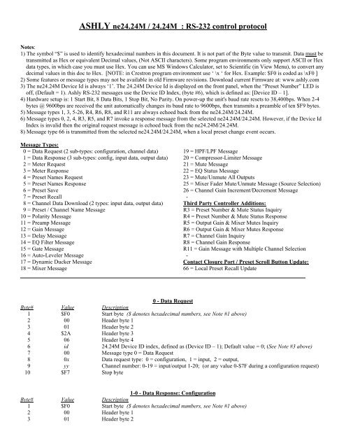
<strong>ASHLY</strong> <strong>ne<strong>24.24M</strong></strong> / <strong>24.24M</strong> : <strong>RS</strong>-<strong>232</strong> <strong>control</strong> <strong>protocol</strong><br />
Notes:<br />
1) The symbol “$” is used to identify hexadecimal numbers in this document. It is not part of the Byte value to transmit. Data must be<br />
transmitted as Hex or equivalent Decimal values, (Not ASCII characters). Some program environments only support ASCII or Hex<br />
data types, in which case you must use Hex. You can use MS Windows Calculator, set to Scientific (in View Menu), to convert any<br />
decimal values in this doc to Hex. [NOTE: in Crestron program environment use ‘ \x ‘ for Hex. Example: $F0 is coded as \xF0 ]<br />
2) Some features or message types may not be available in old Firmware revisions. Download current Firmware at: www.ashly.com<br />
3) The <strong>ne<strong>24.24M</strong></strong> Device Id is always ‘1’. The <strong>24.24M</strong> Device Id is displayed on the front panel, when the “Preset Number” LED is<br />
off, (Default = 1). Ashly <strong>RS</strong>-<strong>232</strong> messages use the Device ID Index, (byte #6), which is defined as: [Device ID – 1].<br />
4) Hardware setup is: 1 Start Bit, 8 Data Bits, 1 Stop Bit, No Parity. On power-up the unit's baud rate resets to 38,400bps. When 2-4<br />
bytes @ 9600bps are received the unit automatically changes its baud rate to 9600bps, then transmits a preamble of ten $F9 bytes.<br />
5) Message types 1, 3, 5-26, R4, R6, R8, and R11 are always echoed back from the <strong>ne<strong>24.24M</strong></strong>/<strong>24.24M</strong>.<br />
6) Message types 0, 2, 4, R3, R5, and R7 invoke a response message from the selected <strong>ne<strong>24.24M</strong></strong>/<strong>24.24M</strong>. However, if the Device Id<br />
Index is invalid then the original request message is echoed back from the <strong>ne<strong>24.24M</strong></strong>/<strong>24.24M</strong>.<br />
8) Message type 66 is transmitted from the selected <strong>ne<strong>24.24M</strong></strong>/<strong>24.24M</strong>, when a local preset change event occurs.<br />
Message Types:<br />
0 = Data Request (2 sub-types: configuration, channel data) 19 = HPF/LPF Message<br />
1 = Data Response (3 sub-types: config, input data, output data) 20 = Compressor-Limiter Message<br />
2 = Meter Request 21 = Mute Message<br />
3 = Meter Response 22 = EQ Status Message<br />
4 = Preset Names Request 23 = Mute/Unmute All Outputs<br />
5 = Preset Names Response 25 = Mixer Fader Mute/Unmute Message (Source Selection)<br />
6 = Preset Save 26 = Channel Gain Increment/Decrement Message<br />
7 = Preset Recall -<br />
8 = Channel Data Download (2 types: input data, output data) Third Party Controller Additions:<br />
9 = Preset / Channel Name Message R3 = Preset Number & Mute Status Inquiry<br />
10 = Polarity Message R4 = Preset Number & Mute Status Response<br />
11 = Preamp Message R5 = Output Gain & Mixer Mutes Inquiry<br />
12 = Gain Message R6 = Output Gain & Mixer Mutes Response<br />
13 = Delay Message R7 = Channel Gain Inquiry<br />
14 = EQ Filter Message R8 = Channel Gain Response<br />
15 = Gate Message R11 = Gain Message with Multiple Channel Selection<br />
16 = Auto-Leveler Message -<br />
17 = Dynamic Ducker Message Contact Closure Port / Preset Scroll Button Update:<br />
18 = Mixer Message 66 = Local Preset Recall Update<br />
0 - Data Request<br />
Byte# Value Description<br />
1 $F0 Start byte ($ denotes hexadecimal numbers, see Note #1 above)<br />
2 00 Header byte 1<br />
3 01 Header byte 2<br />
4 $2A Header byte 3<br />
5 06 Header byte 4<br />
6 id <strong>24.24M</strong> Device ID index, defined as (Device ID – 1); Default value = 0; (See Note #3 above)<br />
7 00 Message type 0 = Data Request<br />
8 0x Data request type: 0 = configuration, 1 = input, 2 = output,<br />
9 yy Channel number: 0-19 = input/output 1-20; (or any value 0-$7F during a configuration request)<br />
10 $F7 Stop byte<br />
1-0 - Data Response: Configuration<br />
Byte# Value Description<br />
1 $F0 Start byte ($ denotes hexadecimal numbers, see Note #1 above)<br />
2 00 Header byte 1<br />
3 01 Header byte 2
4 $2A Header byte 3<br />
5 06 Header byte 4<br />
6 id <strong>24.24M</strong> Device ID index, defined as (Device ID – 1); Default value = 0; (See Note #3 on page 1)<br />
7 01 Message type 1 = Data Response<br />
8 00 Data response type 0 = Configuration<br />
9-28 nn Preset name: 20 ASCII characters in the range $20-$7A, where Byte# 9 is the first name character<br />
29 x-x-5-4-3-2-1-0 (Bit7,6 = 0); Bit5 EXP1 status: 1 = present, 0 = none; Bit4 EXP1 type: 1 = input, 0 = output;<br />
Bit3 EXP2 status; Bit2 EXP2 type; Bit1 EXP3 status; Bit0 EXP3 type;<br />
30 x-x-5-4-x-x-1-0 (Bit7,6 = 0); Bit5 EXP4 status; Bit4 EXP4 type; (Bit3,2 = 0);<br />
Bit1 front switch status: 1 = locked, 0 = enabled; Bit0 front switch type: 1 = preset, 0 = device id<br />
31 pn Preset number, where 0-34 = presets 1-35<br />
32 vv DSP status (xx654321): 1 = valid, 0 = invalid or not installed<br />
33 $F7 Stop byte<br />
1-1 - Data Response: Input<br />
(Response to an input Data Request Message. Refer to file: <strong>24.24M</strong>_2-Input_Message.pdf)<br />
1-2 - Data Response: Output<br />
(Response to an output Data Request Message. Refer to file: <strong>24.24M</strong>_2-Output_Message.pdf)<br />
2 - Meter Request<br />
Byte# Value Description<br />
1 $F0 Start byte ($ denotes hexadecimal numbers, see Note #1 on page 1)<br />
2 00 Header byte 1<br />
3 01 Header byte 2<br />
4 $2A Header byte 3<br />
5 06 Header byte 4<br />
6 id <strong>24.24M</strong> Device ID index, defined as (Device ID – 1); Default value = 0; (See Note #3 on page 1)<br />
7 02 Message type 2 = Meter Request<br />
8 $F7 Stop byte<br />
3 - Meter Response (unit’s reply to meter request)<br />
Byte# Value Description<br />
1 $F0 Start byte ($ denotes hexadecimal numbers, see Note #1 on page 1)<br />
2 00 Header byte 1<br />
3 01 Header byte 2<br />
4 $2A Header byte 3<br />
5 06 Header byte 4<br />
6 id <strong>24.24M</strong> Device ID index, defined as (Device ID – 1); Default value = 0; (See Note #3 on page 1)<br />
7 03 Message type 3 = Meter Response<br />
8 xx Input 1 level<br />
9 xx Input 2 level<br />
10 xx Input 3 level<br />
11 xx Input 4 level<br />
12 xx Output 1 level<br />
13 xx Output 2 level<br />
14 xx Output 3 level<br />
15 xx Output 4 level<br />
16 xx Expansion: Input 5 level / Output 20 level<br />
17 xx Expansion: Input 6 level / Output 19 level<br />
18 xx Expansion: Input 7 level / Output 18 level<br />
19 xx Expansion: Input 8 level / Output 17 level<br />
20 xx Expansion: Input 9 level / Output 16 level<br />
21 xx Expansion: Input 10 level / Output 15 level
22 xx Expansion: Input 11 level / Output 14 level<br />
23 xx Expansion: Input 12 level / Output 13 level<br />
24 xx Expansion: Input 13 level / Output 12 level<br />
25 xx Expansion: Input 14 level / Output 11 level<br />
26 xx Expansion: Input 15 level / Output 10 level<br />
27 xx Expansion: Input 16 level / Output 9 level<br />
28 xx Expansion: Input 17 level / Output 8 level<br />
29 xx Expansion: Input 18 level / Output 7 level<br />
30 xx Expansion: Input 19 level / Output 6 level<br />
31 xx Expansion: Input 20 level / Output 5 level<br />
32 yy Input 1 auto-level, gate status<br />
33 yy Input 2 auto-level, gate status<br />
34 yy Input 3 auto-level, gate status<br />
35 yy Input 4 auto-level, gate status<br />
36 zz Output 1 limiter gain reduction<br />
37 zz Output 2 limiter gain reduction<br />
38 zz Output 3 limiter gain reduction<br />
39 zz Output 4 limiter gain reduction<br />
40 yy/zz Expansion: Input 5 auto-level, gate status / Output 20 limiter gain reduction<br />
41 yy/zz Expansion: Input 6 auto-level, gate status / Output 19 limiter gain reduction<br />
42 yy/zz Expansion: Input 7 auto-level, gate status / Output 18 limiter gain reduction<br />
43 yy/zz Expansion: Input 8 auto-level, gate status / Output 17 limiter gain reduction<br />
44 yy/zz Expansion: Input 9 auto-level, gate status / Output 16 limiter gain reduction<br />
45 yy/zz Expansion: Input 10 auto-level, gate status / Output 15 limiter gain reduction<br />
46 yy/zz Expansion: Input 11 auto-level, gate status / Output 14 limiter gain reduction<br />
47 yy/zz Expansion: Input 12 auto-level, gate status / Output 13 limiter gain reduction<br />
48 yy/zz Expansion: Input 13 auto-level, gate status / Output 12 limiter gain reduction<br />
49 yy/zz Expansion: Input 14 auto-level, gate status / Output 11 limiter gain reduction<br />
50 yy/zz Expansion: Input 15 auto-level, gate status / Output 10 limiter gain reduction<br />
51 yy/zz Expansion: Input 16 auto-level, gate status / Output 9 limiter gain reduction<br />
52 yy/zz Expansion: Input 17 auto-level, gate status / Output 8 limiter gain reduction<br />
53 yy/zz Expansion: Input 18 auto-level, gate status / Output 7 limiter gain reduction<br />
54 yy/zz Expansion: Input 19 auto-level, gate status / Output 6 limiter gain reduction<br />
55 yy/zz Expansion: Input 20 auto-level, gate status / Output 5 limiter gain reduction<br />
56 0-1-2-3-4-5-6-7 Inputs 1-7 ducker status bits: 0 = no ducking attenuation applied, 1 = input is being ducked<br />
57 0-8-9-10-…14 Inputs 8-14 ducker status bits: 0 = no ducking attenuation applied, 1 = input is being ducked<br />
58 0-15-16-...20-0 Inputs 15-20 ducker status bits: 0 = no ducking attenuation applied, 1 = input is being ducked<br />
59 $F7 Sys-Ex end of transmission byte<br />
Meter Notes:<br />
xx - input and output level bytes use the following binary format: 0CLLLLLL<br />
Bits 5-0 represent the dBu level, where 0 =
5 - Preset Names Response (unit’s reply to preset names request)<br />
Byte# Value Description<br />
1 $F0 Start byte ($ denotes hexadecimal numbers, see Note #1 on page 1)<br />
2 00 Header byte 1<br />
3 01 Header byte 2<br />
4 $2A Header byte 3<br />
5 06 Header byte 4<br />
6 id <strong>24.24M</strong> Device ID index, defined as (Device ID – 1); Default value = 0; (See Note #3 on page 1)<br />
7 05 Message type 5 = Preset Names Response<br />
8-707 yy 700 ASCII name characters, 20 per preset starting w/preset #1, (valid range: $20 to $7A)<br />
708 $F7 Stop byte<br />
6 - Preset Save<br />
Byte# Value Description<br />
1 $F0 Start byte ($ denotes hexadecimal numbers, see Note #1 on page 1)<br />
2 00 Header byte 1<br />
3 01 Header byte 2<br />
4 $2A Header byte 3<br />
5 06 Header byte 4<br />
6 id <strong>24.24M</strong> Device ID index, defined as (Device ID – 1); Default value = 0; (See Note #3 on page 1)<br />
7 06 Message type 6 = Preset Save<br />
8 xx Preset number to save to, 0-34 (Presets 1-35)<br />
9-28 yy 20 ASCII name characters, ($20 to $7A)<br />
29 $F7 Stop byte<br />
7 - Preset Recall<br />
Byte# Value Description<br />
1 $F0 Start byte ($ denotes hexadecimal numbers, see Note #1 on page 1)<br />
2 00 Header byte 1<br />
3 01 Header byte 2<br />
4 $2A Header byte 3<br />
5 06 Header byte 4<br />
6 id <strong>24.24M</strong> Device ID index, defined as (Device ID – 1); Default value = 0; (See Note #3 on page 1)<br />
7 07 Message type 7 = Preset Recall<br />
8 xx Preset number to recall - 1, (value: 0-34 = Preset 1-35 respectively)<br />
9 zz Mute status: 0 = as per preset settings, 1-$7F = force all channels to mute<br />
10 $F7 Stop byte<br />
8-1 - Data Download: Input Channel<br />
(Identical to Data Response Message, except message type byte = 08. Refer to file: <strong>24.24M</strong>_2-Input_Message.pdf)<br />
8-2 - Data Download: Output Channel<br />
(Identical to Data Response Message, except message type byte = 08. Refer to file: <strong>24.24M</strong>_2-Output_Message.pdf)<br />
9 - Preset / Channel Name Message<br />
Byte# Value Description<br />
1 $F0 Start byte ($ denotes hexadecimal numbers, see Note #1 on page 1)<br />
2 00 Header byte 1<br />
3 01 Header byte 2
4 $2A Header byte 3<br />
5 06 Header byte 4<br />
6 id <strong>24.24M</strong> Device ID index, defined as (Device ID – 1); Default value = 0; (See Note #3 on page 1)<br />
7 09 Message type 9 = Preset / Channel Name Message<br />
8 tt Type: 0-19 = Inputs 1-20, 64-83 = Outputs 1-20, 127 = Working Preset<br />
9-28 yy 20 ASCII name characters, (valid range: $20 to $7A)<br />
29 $F7 Stop byte<br />
10 - Polarity Message<br />
Byte# Value Description<br />
1 $F0 Start byte ($ denotes hexadecimal numbers, see Note #1 on page 1)<br />
2 00 Header byte 1<br />
3 01 Header byte 2<br />
4 $2A Header byte 3<br />
5 06 Header byte 4<br />
6 id <strong>24.24M</strong> Device ID index, defined as (Device ID – 1); Default value = 0; (See Note #3 on page 1)<br />
7 $0A Message type 10 ($0A) = Polarity Message<br />
8 xx Channel: 0-19 = Inputs 1-20, 64-83 = Outputs 1-20<br />
9 yy Polarity: 0 = normal; 1-$7F = inverted<br />
10 $F7 Stop byte<br />
11 - Preamp Message<br />
Byte# Value Description<br />
1 $F0 Start byte ($ denotes hexadecimal numbers, see Note #1 on page 1)<br />
2 00 Header byte 1<br />
3 01 Header byte 2<br />
4 $2A Header byte 3<br />
5 06 Header byte 4<br />
6 id <strong>24.24M</strong> Device ID index, defined as (Device ID – 1); Default value = 0; (See Note #3 on page 1)<br />
7 $0B Message type 11 ($0B) = Preamp Message<br />
8 xx Channel: 0-19 = Inputs 1-20<br />
9 yy Preamp gain: 0 = 0 dB; 20 = 20 dB; 40 = 40 dB; 60 = 60 dB<br />
10 zz Phantom power: 0 = off; $1-7F = on<br />
11 $F7 Stop byte<br />
12 - Gain Message<br />
Byte# Value Description<br />
1 $F0 Start byte ($ denotes hexadecimal numbers, see Note #1 on page 1)<br />
2 00 Header byte 1<br />
3 01 Header byte 2<br />
4 $2A Header byte 3<br />
5 06 Header byte 4<br />
6 id <strong>24.24M</strong> Device ID index, defined as (Device ID – 1); Default value = 0; (See Note #3 on page 1)<br />
7 $0C Message type 12 ($0C) = Gain Message<br />
8 xx Channel: 0-19 = Inputs 1-20, 64-83 = Outputs 1-20<br />
9 yy Gain bits 13-7; 7692 to 8312 = -50 to +12 dB in 0.1 dB steps, (8192 = 0 dB)<br />
10 zz Gain bits 6-0; [see Sample Gain Bytes at the end of this document]<br />
11 $F7 Stop byte<br />
13 - Delay Message<br />
Byte# Value Description<br />
1 $F0 Start byte ($ denotes hexadecimal numbers, see Note #1 on page 1)<br />
2 00 Header byte 1<br />
3 01 Header byte 2
4 $2A Header byte 3<br />
5 06 Header byte 4<br />
6 id <strong>24.24M</strong> Device ID index, defined as (Device ID – 1); Default value = 0; (See Note #3 on page 1)<br />
7 $0D Message type 13 ($0D) = Delay Message<br />
8 xx Channel: 0-19 = Inputs 1-20, 64-83 = Outputs 1-20<br />
9 yy Delay bits 20-14; Delay time in seconds = (21-bit Delay Word)/(48,000)<br />
10 yy Delay bits 13-7; Delay word range = 0-32,760 (0-682.500 ms)<br />
11 yy Delay bits 6-0;<br />
12 $F7 Stop byte<br />
Note: there is an additional propagation delay of 1.46 ms from any input to any output, due to the digital converters & DSP.<br />
14 - EQ Filter Message<br />
Byte# Value Description<br />
1 $F0 Start byte ($ denotes hexadecimal numbers, see Note #1 on page 1)<br />
2 00 Header byte 1<br />
3 01 Header byte 2<br />
4 $2A Header byte 3<br />
5 06 Header byte 4<br />
6 id <strong>24.24M</strong> Device ID index, defined as (Device ID – 1); Default value = 0; (See Note #3 on page 1)<br />
7 $0E Message type 14 ($0E) = EQ Filter Message<br />
8 xx Channel: 0-19 = Inputs 1-20, 64-83 = Outputs 1-20<br />
9 yy Filter number: 0 = filter 1, 1 = filter 2, etc…<br />
10 ff Frequency bit 14 (xxxxxxxE) 15-bit Frequency Word = actual frequency in Hertz<br />
11 ff Frequency bits 13-7 (xDCBA987) [see limits below]<br />
12 ff Frequency bits 6-0 (x6543210) [also, see Sample Frequency Bytes at the end of this doc]<br />
13 qq Q-index range: 11-107 = 1/64 to 4 oct [see Bandwidth vs. Q-index Bytes at the end of this doc]<br />
14 gg Filter Gain bits 13-7 (xDCBA987) [see limits below]<br />
15 gg Filter Gain bits 6-0 (x6543210) [also, see Sample Gain Bytes at the end of this document]<br />
16 st Status & Type: bit 6 (status) - 0 = bypass, 1 = active;<br />
lower nibble (type) - Value 0-5 = PEQ, LS1, LS2, HS1, HS2, Allpass<br />
17 $F7 Stop byte<br />
EQ Notes:<br />
Parametric filter frequency range: 20 Hz to 20,000 Hz<br />
Parametric filter gain range: -30dB to +15dB in 0.1dB steps; 14-bit Gain Word = 7892 to 8342 (8192 = 0dB)<br />
Low Shelf frequency range: 20 Hz to 2,000 Hz<br />
High Shelf frequency range: 3,890 Hz to 20,000 Hz<br />
Shelf filter gain range: -15dB to +15dB in 0.1dB steps; 14-bit Gain Word = 8042 to 8342 (8192 = 0dB)<br />
15 - Gate Message<br />
Byte# Value Description<br />
1 $F0 Start byte ($ denotes hexadecimal numbers, see Note #1 on page 1)<br />
2 00 Header byte 1<br />
3 01 Header byte 2<br />
4 $2A Header byte 3<br />
5 06 Header byte 4<br />
6 id <strong>24.24M</strong> Device ID index, defined as (Device ID – 1); Default value = 0; (See Note #3 on page 1)<br />
7 $0F Message type 15 ($0F) = Gate Message<br />
8 xx Channel: 0-19 = Inputs 1-20<br />
9 tt Threshold: 20-120 = -80 to +20 dBu<br />
10 ff Floor: 0-19 = Off (-INF); 20-100 = -80 to 0 dBu<br />
11 ar Attack rate: 0-7 = 0.2, 0.5, 1, 2, 5, 10, 20, 50 ms/dB<br />
12 rr Release rate: 0-7 = 5, 10, 20, 50, 100, 200, 500, 1000 ms/dB<br />
13 ss Status: 0 = bypass; $1-7F = active<br />
14 $F7 Stop byte
16 - Auto-Leveler Message<br />
Byte# Value Description<br />
1 $F0 Start byte ($ denotes hexadecimal numbers, see Note #1 on page 1)<br />
2 00 Header byte 1<br />
3 01 Header byte 2<br />
4 $2A Header byte 3<br />
5 06 Header byte 4<br />
6 id <strong>24.24M</strong> Device ID index, defined as (Device ID – 1); Default value = 0; (See Note #3 on page 1)<br />
7 $10 Message type 16 ($10) = Auto-Leveler Message<br />
8 xx Channel: 0-19 = Inputs 1-20<br />
9 tl Target Level: 60-120 = -40 to +20 dBu<br />
10 tt Threshold: 70-100 = -30 to 0 dB below the target level<br />
11 rr Ratio: 0-6 = 1.2, 1.5, 2, 3, 4, 6, 10 to 1<br />
12 gr Gain change rates: Bits2-0 (low nibble) = increase rate, Bits6-4 (high nibble) = decrease rate<br />
value 0-7 = 5, 10, 20, 50, 100, 200, 500, 1000 ms/dB<br />
13 ht Hold time: 0-6 = 0 to 6 seconds<br />
14 ss Status: 0 = bypass; $1-7F = active<br />
15 $F7 Stop byte<br />
17 - Dynamic Ducker Message<br />
Byte# Value Description<br />
1 $F0 Start byte ($ denotes hexadecimal numbers, see Note #1 on page 1)<br />
2 00 Header byte 1<br />
3 01 Header byte 2<br />
4 $2A Header byte 3<br />
5 06 Header byte 4<br />
6 id <strong>24.24M</strong> Device ID index, defined as (Device ID – 1); Default value = 0; (See Note #3 on page 1)<br />
7 $11 Message type 17 ($11) = Dynamic Ducker Message<br />
8 xx Channel: 0-19 = Inputs 1-20<br />
9 tt Threshold: 20-120 = -80 to +20 dBu<br />
10 dd Depth (amount of attenuation): 0-69 = Off (-INF); 70-100 = -30 to 0 dBu<br />
11 rr Release rate: 0-7 = 5, 10, 20, 50, 100, 200, 500, 1000 ms/dB<br />
12 ss Status: 0 = bypass; 1 = high priority trigger; 2 = low priority trigger; 3 = ducked program<br />
13 $F7 Stop byte<br />
18 - Mixer Message<br />
Byte# Value Description<br />
1 $F0 Start byte ($ denotes hexadecimal numbers, see Note #1 on page 1)<br />
2 00 Header byte 1<br />
3 01 Header byte 2<br />
4 $2A Header byte 3<br />
5 06 Header byte 4<br />
6 id <strong>24.24M</strong> Device ID index, defined as (Device ID – 1); Default value = 0; (See Note #3 on page 1)<br />
7 $12 Message type 18 ($12) = Mixer Message<br />
8 xx Channel: 64-83 = Outputs 1-20<br />
9 ss Source: 0-19 = Inputs 1-20<br />
10 ll Level: 0 = -INF; 1-63 = -50 to +12 dB<br />
11 ss Status: 0 = bypass; 1-7F = active<br />
12 mm Mute: 0 = not muted; $1-7F = muted<br />
13 $F7 Stop byte<br />
19 - HPF/LPF Message<br />
Byte# Value Description<br />
1 $F0 Start byte ($ denotes hexadecimal numbers, see Note #1 on page 1)<br />
2 00 Header byte 1<br />
3 01 Header byte 2
4 $2A Header byte 3<br />
5 06 Header byte 4<br />
6 id <strong>24.24M</strong> Device ID index, defined as (Device ID – 1); Default value = 0; (See Note #3 on page 1)<br />
7 $13 Message type 19 ($13) = HPF/LPF Message<br />
8 xx Channel: 64-83 = Outputs 1-20<br />
9 yy Filter: 0 = high-pass filter; 1 = low-pass filter<br />
10 ff Frequency bit 14 (xxxxxxxE) 15-bit Frequency Word = actual frequency in Hertz<br />
11 ff Frequency bits 13-7 (xDCBA987) [see Sample Frequency Bytes at the end of this document]<br />
12 ff Frequency bits 6-0 (x6543210)<br />
13 tt Type: 0-10 = ButterWorth2, Bessel2, LinkwitzRiley2, BW/LR3, B3, BW4, B4, LR4, BW8, B8, LR8<br />
14 $F7 Stop byte<br />
20 - Compressor-Limiter Message<br />
Byte# Value Description<br />
1 $F0 Start byte ($ denotes hexadecimal numbers, see Note #1 on page 1)<br />
2 00 Header byte 1<br />
3 01 Header byte 2<br />
4 $2A Header byte 3<br />
5 06 Header byte 4<br />
6 id <strong>24.24M</strong> Device ID index, defined as (Device ID – 1); Default value = 0; (See Note #3 on page 1)<br />
7 $14 Message type 20 ($14) = Compressor-Limiter Message<br />
8 xx Channel: 64-83 = Outputs 1-20<br />
9 tt Threshold: 80-120 = -20 to +20 dBu<br />
10 rr Ratio: 0-8 = 1.2, 1.5, 2, 3, 4, 6, 10, 20, INF to 1<br />
11 ar Attack rate: 0-7 = 0.2, 0.5, 1, 2, 5, 10, 20, 50ms/dB<br />
12 rr Release rate: 0-7 = 5, 10, 20, 50, 100, 200, 500, 1000ms/dB<br />
13 ss Status: 0 = bypass; $1-7F = active<br />
14 ll Link: 0 = not linked; $1-7F = linked<br />
15 $F7 Stop byte<br />
21 - Channel Mute Message<br />
Byte# Value Description<br />
1 $F0 Start byte ($ denotes hexadecimal numbers, see Note #1 on page 1)<br />
2 00 Header byte 1<br />
3 01 Header byte 2<br />
4 $2A Header byte 3<br />
5 06 Header byte 4<br />
6 id <strong>24.24M</strong> Device ID index, defined as (Device ID – 1); Default value = 0; (See Note #3 on page 1)<br />
7 $15 Message type 21 ($15) = Channel Mute Message<br />
8 xx Channel: 0-19 = Inputs 1-20, 64-83 = Outputs 1-20<br />
9 yy Mute status, where 0 = not muted, $1-7F = muted<br />
10 $F7 Stop byte<br />
22 - EQ Status Message<br />
Byte# Value Description<br />
1 $F0 Start byte ($ denotes hexadecimal numbers, see Note #1 on page 1)<br />
2 00 Header byte 1<br />
3 01 Header byte 2<br />
4 $2A Header byte 3<br />
5 06 Header byte 4<br />
6 id <strong>24.24M</strong> Device ID index, defined as (Device ID – 1); Default value = 0; (See Note #3 on page 1)<br />
7 $16 Message type 22 ($16) = EQ Status Message<br />
8 xx Channel: 0-19 = Inputs 1-20, 64-83 = Outputs 1-20<br />
9 yy EQ Status: 0 = bypass; $1-7F = active<br />
10 $F7 Stop byte
23 - Mute/Unmute All Outputs Message<br />
Byte# Value Description<br />
1 $F0 Start byte ($ denotes hexadecimal numbers, see Note #1 on page 1)<br />
2 00 Header byte 1<br />
3 01 Header byte 2<br />
4 $2A Header byte 3<br />
5 06 Header byte 4<br />
6 id <strong>24.24M</strong> Device ID index, defined as (Device ID – 1); Default value = 0; (See Note #3 on page 1)<br />
7 $17 Message type 23 ($17) = Mute/Unmute All Outputs Message<br />
8 yy Status: 0 = unmute all outputs; $1-7F = mute all outputs<br />
9 $F7 Stop byte<br />
25 - Mixer Fader Mute/Unmute Message<br />
Byte# Value Description<br />
1 $F0 Start byte ($ denotes hexadecimal numbers, see Note #1 on page 1)<br />
2 00 Header byte 1<br />
3 01 Header byte 2<br />
4 $2A Header byte 3<br />
5 06 Header byte 4<br />
6 id <strong>24.24M</strong> Device ID index, defined as (Device ID – 1); Default value = 0; (See Note #3 on page 1)<br />
7 $19 Message type 25 ($19) = Routing Source Enable/Disable Message<br />
8 xx Channel: 64-83 = Outputs 1-20<br />
9 ss Source (mix fader): 0-19 = Inputs 1-20<br />
10 yy New Mixer Fader Mute Status: 0 = not muted, 1-$7F = muted<br />
11 $F7 Stop byte<br />
26 - Gain Increment/Decrement Message<br />
Byte# Value Description<br />
1 $F0 Start byte ($ denotes hexadecimal numbers, see Note #1 on page 1)<br />
2 00 Header byte 1<br />
3 01 Header byte 2<br />
4 $2A Header byte 3<br />
5 06 Header byte 4<br />
6 id <strong>24.24M</strong> Device ID index, defined as (Device ID – 1); Default value = 0; (See Note #3 on page 1)<br />
7 $1A Message type 26 ($1A) = Increment/Decrement Gain Message<br />
8 xx Channel: 0-19 ($0-13) = Inputs 1-20, 64-83 ($40-53) = Outputs 1-20<br />
9 vv $00-$03 = .5dB, 1dB, 2dB, 3dB decrement; $10-$13 = .5dB, 1dB, 2dB, 3dB increment<br />
10 $F7 Stop byte<br />
R3 – Preset Number & Mute Status Inquiry<br />
Byte# Value Description<br />
1 $F0 Start byte ($ denotes hexadecimal numbers)<br />
2 00 Header byte 1<br />
3 01 Header byte 2<br />
4 $2A Header byte 3<br />
5 $0C Third party <strong>control</strong>ler message class identifier<br />
6 id <strong>24.24M</strong> Device ID index, defined as (Device ID – 1); Default value = 0; (See Note #3 on page 1)<br />
7 03 Message type 03 = Target Device Preset Number & Mute Status Inquiry<br />
8 00 Third party <strong>control</strong>ler identification byte 1<br />
9 01 Third party <strong>control</strong>ler identification byte 2<br />
10 $F7 Stop Byte
R4 – Preset Number & Mute Status Response<br />
Byte# Value Description<br />
1 $F0 Start byte ($ denotes hexadecimal numbers)<br />
2 00 Header byte 1<br />
3 01 Header byte 2<br />
4 $2A Header byte 3<br />
5 $0C Third party <strong>control</strong>ler message class identifier<br />
6 id <strong>24.24M</strong> Device ID index, defined as (Device ID – 1); Default value = 0; (See Note #3 on page 1)<br />
7 $04 Message type 04 = Target Device Preset Number & Mute Status Response<br />
8 00 Third party <strong>control</strong>ler identification byte 1<br />
9 01 Third party <strong>control</strong>ler identification byte 2<br />
10 pn Target device preset number, (<strong>24.24M</strong> preset number - 1)<br />
11 0-7-6-5-4-3-2-1 Target device inputs 1-7 mute status, note: high bit means channel is muted<br />
12 0-14-13-12-11-10-9-8 Target device inputs 8-14 mute status<br />
13 0-x-20-19-18-17-16-15 Target device inputs 15-20 mute status<br />
14 sp Target device input mute status spare<br />
15 0-7-6-5-4-3-2-1 Target device outputs 1-7 mute status, note: high bit means channel is muted<br />
16 0-14-13-12-11-10-9-8 Target device outputs 8-14 mute status<br />
17 0-x-20-19-18-17-16-15 Target device outputs 15-20 mute status<br />
18 sp Target device output mute status spare<br />
19 $F7 Stop Byte<br />
R5 – Output Gain & Mixer Mutes Inquiry<br />
Byte# Value Description<br />
1 $F0 Start byte ($ denotes hexadecimal numbers)<br />
2 00 Header byte 1<br />
3 01 Header byte 2<br />
4 $2A Header byte 3<br />
5 $0C Third party <strong>control</strong>ler message class identifier<br />
6 id <strong>24.24M</strong> Device ID index, defined as (Device ID – 1); Default value = 0; (See Note #3 on page 1)<br />
7 $05 Message type 05 = Target Device Output Gain & Mixer Mutes Inquiry<br />
8 00 Third party <strong>control</strong>ler identification byte 1<br />
9 01 Third party <strong>control</strong>ler identification byte 2<br />
10 nn Target Device output channel<br />
11 $F7 Stop Byte<br />
R6 – Output Gain & Mixer Mutes Response<br />
Byte# Value Description<br />
1 $F0 Start byte ($ denotes hexadecimal numbers)<br />
2 00 Header byte 1<br />
3 01 Header byte 2<br />
4 $2A Header byte 3<br />
5 $0C Third party <strong>control</strong>ler message class identifier<br />
6 id <strong>24.24M</strong> Device ID index, defined as (Device ID – 1); Default value = 0; (See Note #3 on page 1)<br />
7 $06 Message type 06 = Target Device Output Gain & Mixer Mutes Response<br />
8 00 Third party <strong>control</strong>ler identification byte 1<br />
9 01 Third party <strong>control</strong>ler identification byte 2<br />
10 nn Target device output channel requested, 0 to n = output 1 to n+1<br />
11 gg Target device output channel gain, formatted in the range of 0-99: 0 = -INF, 1-99 = -50 to +12dB<br />
12 0-7-6-5-4-3-2-1 Target device output channel’s source 1-7 mute status, note: high bit means channel is muted<br />
13 0-14-13-12-11-10-9-8 Target device output channel’s source 8-14 mute status<br />
14 0-x-20-19-18-17-16-15 Target device output channel’s source 15-20 mute status<br />
15 sp Target device output channel’s source spare<br />
16 $F7 Stop Byte
R7 – Channel Gain Inquiry<br />
Byte# Value Description<br />
1 $F0 Start byte ($ denotes hexadecimal numbers)<br />
2 00 Header byte 1<br />
3 01 Header byte 2<br />
4 $2A Header byte 3<br />
5 $0C Third party <strong>control</strong>ler message class identifier<br />
6 id <strong>24.24M</strong> Device ID index, defined as (Device ID – 1); Default value = 0; (See Note #3 on page 1)<br />
7 $07 Message type 07 = Target Device Channel Gain Inquiry<br />
8 00 Third party <strong>control</strong>ler identification byte 1<br />
9 01 Third party <strong>control</strong>ler identification byte 2<br />
10 nn Target Device channel: 0-63 = inputs 1-64, 64-127 = outputs 1-64<br />
11 $F7 Stop Byte<br />
R8 – Channel Gain Response<br />
Byte# Value Description<br />
1 $F0 Start byte ($ denotes hexadecimal numbers)<br />
2 00 Header byte 1<br />
3 01 Header byte 2<br />
4 $2A Header byte 3<br />
5 $0C Third party <strong>control</strong>ler message class identifier<br />
6 id <strong>24.24M</strong> Device ID index, defined as (Device ID – 1); Default value = 0; (See Note #3 on page 1)<br />
7 $08 Message type 08 = Target Device Channel Gain Response<br />
8 00 Third party <strong>control</strong>ler identification byte 1<br />
9 01 Third party <strong>control</strong>ler identification byte 2<br />
10 nn Target Device channel: 0-63 = inputs 1-64, 64-127 = outputs 1-64<br />
11 gg Target device channel gain, formatted in the range of 0-99: 0 = -INF, 1-99 = -50 to +12dB<br />
12 $F7 Stop Byte<br />
R11 – Gain Message with Multiple Channel Selection<br />
Byte# Value Description<br />
1 $F0 Start byte ($ denotes hexadecimal numbers)<br />
2 00 Header byte 1<br />
3 01 Header byte 2<br />
4 $2A Header byte 3<br />
5 $0C Third party <strong>control</strong>ler message class identifier<br />
6 id <strong>24.24M</strong> Device ID index, defined as (Device ID – 1); Default value = 0; (See Note #3 on page 1)<br />
7 $0B Message type 11 = Target Device Gain Message<br />
8 00 Third party <strong>control</strong>ler identification byte 1<br />
9 01 Third party <strong>control</strong>ler identification byte 2<br />
10 gg Target device new gain value, formatted in the range of 0-99: 0 = -INF, 1-99 = -50 to +12dB<br />
11 0-7-6-5-4-3-2-1 Target device inputs 1-7 selection, note: high bit means channel is selected for new gain value<br />
12 0-14-13-12-11-10-9-8 Target device inputs 8-14 selection<br />
13 0-x-20-19-18-17-16-15 Target device inputs 15-20 selection<br />
14 sp Target device input selection spare<br />
15 0-7-6-5-4-3-2-1 Target device outputs 1-7 selection<br />
16 0-14-13-12-11-10-9-8 Target device outputs 8-14 selection<br />
17 0-x-20-19-18-17-16-15 Target device outputs 15-20 selection<br />
18 sp Target device output selection spare<br />
19 $F7 Stop Byte<br />
66 - Local Preset Recall Update<br />
Byte# Value Description<br />
1 $F0 Start byte ($ denotes hexadecimal numbers, see Note #1 on page 1)<br />
2 00 Header byte 1<br />
3 01 Header byte 2
4 $2A Header byte 3<br />
5 06 Header byte 4<br />
6 id <strong>24.24M</strong> Device ID index, defined as (Device ID – 1); Default value = 0; (See Note #3 on page 1)<br />
7 $42 Message type 66 ($42) = Local Preset Recall Update<br />
8 pp New Preset #: 0 = Preset 1, 1 = Preset 2, … 34 = Preset 35<br />
9 $F7 Stop byte<br />
Bandwidth vs. Q-index Byte to Transmit ($ denotes Hexadecimal)<br />
BW = (1/3) * 2 ^ [(Q-index - 64)/12]<br />
BW(oct) Q-index BW(oct) Q-index BW(oct) Q-index<br />
0.016 $0B 0.105 $2C 0.667 $4C<br />
0.017 $0C 0.111 $2D 0.706 $4D<br />
0.018 $0D 0.118 $2E 0.748 $4E<br />
0.019 $0E 0.125 $2F 0.793 $4F<br />
0.020 $0F 0.132 $30 0.840 $50<br />
0.021 $10 0.140 $31 0.890 $51<br />
0.022 $11 0.148 $32 0.943 $52<br />
0.023 $12 0.157 $33 1.00 $53<br />
0.025 $13 0.167 $34 1.06 $54<br />
0.026 $14 0.177 $35 1.12 $55<br />
0.028 $15 0.187 $36 1.19 $56<br />
0.029 $16 0.198 $37 1.26 $57<br />
0.031 $17 0.210 $38 1.33 $58<br />
0.033 $18 0.222 $39 1.41 $59<br />
0.035 $19 0.236 $3A 1.50 $5A<br />
0.037 $1A 0.250 $3B 1.59 $5B<br />
0.039 $1B 0.265 $3C 1.68 $5C<br />
0.042 $1C 0.280 $3D 1.78 $5D<br />
0.044 $1D 0.297 $3E 1.89 $5E<br />
0.047 $1E 0.315 $3F 2.00 $5F<br />
0.050 $1F 0.333 $40 2.12 $60<br />
0.052 $20 0.353 $41 2.24 $61<br />
0.056 $21 0.374 $42 2.38 $62<br />
0.059 $22 0.396 $43 2.52 $63<br />
0.062 $23 0.420 $44 2.67 $64<br />
0.066 $24 0.445 $45 2.83 $65<br />
0.070 $25 0.471 $46 2.99 $66<br />
0.074 $26 0.499 $47 3.17 $67<br />
0.079 $27 0.529 $48 3.36 $68<br />
0.083 $28 0.561 $49 3.56 $69<br />
0.088 $29 0.594 $4A 3.77 $6A<br />
0.094 $2A 0.629 $4B 4.00 $6B<br />
0.099 $2B
Sample Gain Bytes to Transmit ($ denotes Hexadecimal)<br />
Gain(dB) Gain Value Byte1(bits13-7) Byte2(bits6-0)<br />
+15 8342 $41 $16<br />
+14 8332 $41 $0C<br />
+13 8322 $41 $02<br />
+12 8312 $40 $78<br />
+11 8302 $40 $6E<br />
+10 8292 $40 $64<br />
+ 9 8282 $40 $5A<br />
+ 8 8272 $40 $50<br />
+ 7 8262 $40 $46<br />
+ 6 8252 $40 $3C<br />
+ 5 8242 $40 $32<br />
+ 4 8<strong>232</strong> $40 $28<br />
+ 3 8222 $40 $1E<br />
+ 2 8212 $40 $14<br />
+ 1 8202 $40 $0A<br />
0 8192 $40 $00<br />
- 1 8182 $3F $76<br />
- 2 8172 $3F $6C<br />
- 3 8162 $3F $62<br />
- 4 8152 $3F $58<br />
- 5 8142 $3F $4E<br />
- 6 8132 $3F $44<br />
- 7 8122 $3F $3A<br />
- 8 8112 $3F $30<br />
- 9 8102 $3F $26<br />
-10 8092 $3F $1C<br />
-11 8082 $3F $12<br />
-12 8072 $3F $08<br />
-13 8062 $3E $7E<br />
-14 8052 $3E $74<br />
-15 8042 $3E $6A<br />
-16 8032 $3E $60<br />
-17 8022 $3E $56<br />
-18 8012 $3E $4C<br />
-19 8002 $3E $42<br />
-20 7992 $3E $38<br />
-21 7982 $3E $2E<br />
-22 7972 $3E $24<br />
-23 7962 $3E $1A<br />
-24 7952 $3E $10<br />
-25 7942 $3E $06<br />
-26 7932 $3D $7C<br />
-27 7922 $3D $72<br />
-28 7912 $3D $68<br />
-29 7902 $3D $5E<br />
-30 7892 $3D $54<br />
-31 7882 $3D $4A<br />
-32 7872 $3D $40<br />
-33 7862 $3D $36<br />
-34 7852 $3D $2C<br />
-35 7842 $3D $22<br />
-36 7832 $3D $18<br />
-37 7822 $3D $0E<br />
-38 7812 $3D $04<br />
-39 7802 $3C $7A<br />
-40 7792 $3C $70<br />
-41 7782 $3C $66<br />
-42 7772 $3C $5C<br />
-43 7762 $3C $52<br />
-44 7752 $3C $48<br />
-45 7742 $3C $3E<br />
-46 7732 $3C $34<br />
-47 7722 $3C $2A<br />
-48 7712 $3C $20<br />
-49 7702 $3C $16<br />
-50 7692 $3C $0C<br />
MUTE 7691 $3C $0B
Sample Frequency Bytes to Transmit ($ denotes Hexadecimal)<br />
Frequency(Hz) Byte1(bit14) Byte2(bits13-7) Byte3(bits6-0)<br />
LPF-Off $01 $1C $41<br />
20,000 $01 $1C $40<br />
19,500 $01 $18 $2C<br />
19,000 $01 $14 $38<br />
18,500 $01 $10 $44<br />
18,000 $01 $0C $50<br />
17,500 $01 $08 $5C<br />
17,000 $01 $04 $68<br />
16,500 $01 $00 $74<br />
16,000 $00 $7D $00<br />
15,500 $00 $79 $0C<br />
15,000 $00 $75 $18<br />
14,500 $00 $71 $24<br />
14,000 $00 $6D $30<br />
13,500 $00 $69 $3C<br />
13,000 $00 $65 $48<br />
12,500 $00 $61 $54<br />
12,000 $00 $5D $60<br />
11,500 $00 $59 $6C<br />
11,000 $00 $55 $78<br />
10,500 $00 $52 $04<br />
10,000 $00 $4E $10<br />
9,500 $00 $4A $1C<br />
9,000 $00 $46 $28<br />
8,500 $00 $42 $34<br />
8,000 $00 $3E $40<br />
7,500 $00 $3A $4C<br />
7,000 $00 $36 $58<br />
6,500 $00 $32 $64<br />
6,000 $00 $2E $70<br />
5,500 $00 $2A $7C<br />
5,000 $00 $27 $08<br />
4,500 $00 $23 $14<br />
4,000 $00 $1F $20<br />
3,500 $00 $1B $2C<br />
3,000 $00 $17 $38<br />
2,500 $00 $13 $44<br />
2,000 $00 $0F $50<br />
1,500 $00 $0B $5C<br />
1,000 $00 $07 $68<br />
900 $00 $07 $04<br />
800 $00 $06 $20<br />
700 $00 $05 $3C<br />
600 $00 $04 $58<br />
500 $00 $03 $74<br />
400 $00 $03 $10<br />
300 $00 $02 $2C<br />
200 $00 $01 $48<br />
100 $00 $00 $64<br />
90 $00 $00 $5A<br />
80 $00 $00 $50<br />
70 $00 $00 $46<br />
60 $00 $00 $3C<br />
50 $00 $00 $32<br />
40 $00 $00 $28<br />
30 $00 $00 $1E<br />
20 $00 $00 $14<br />
HPF-Off $00 $00 $13