RS7 Series Instruction Manual - Benshaw
RS7 Series Instruction Manual - Benshaw
RS7 Series Instruction Manual - Benshaw

You also want an ePaper? Increase the reach of your titles
YUMPU automatically turns print PDFs into web optimized ePapers that Google loves.
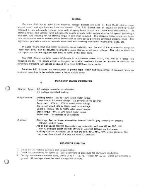
GENERAL<br />
<strong>Benshaw</strong> <strong>RS7</strong> <strong>Series</strong> Solid State Reduced Voltage Starters are used for three-phase squirrel cage,<br />
wound rotor, and synchronous induction motors, The <strong>RS7</strong> Starter has an adjustable starting iorque<br />
followed by an adjustable voltage ramp with stopping brake torque and brake time adjustments. The<br />
starting torque and voltage ramp adjustments enable smooth motor acceleration to full speed, providing a<br />
soft start, and allowing for full starting torque if and when required. The stopping brake torque and brake<br />
time adjustments enable smooth motor deceleration to zero speed providing controlled stopping times. This<br />
adjustment procedure reduces hazards associated with coasting machinery, overhauling loads, etc.<br />
In cases where load and motor conditions cause instability near the end of the acceleration ramp, an<br />
accel kicks circuit can be adjusted to provide a quick step-up to full motor voltage. The point at which the<br />
step-up occurs can be adjusted from 50% to 100% of the accel ramp.<br />
The <strong>RS7</strong> Starter contains seven SCRs--six in a full-wave power circuit, and one as a gated free<br />
wheeling diode. The power circuit is designed to provide maximum torque per ampere to eliminate the<br />
potentially damaging DC voltage produced by a three SCR/three diode starter.<br />
<strong>Benshaw</strong> <strong>RS7</strong> Starters are constructed to permit rapid repair and replacement if required; ensuring<br />
minimum downtime in the unlikely event a failure should occur.<br />
DC INJECTION BRAKING SPECIFiCATION<br />
•Starter Type: AC voltage controlled acceleration<br />
DC voltage controlled braking<br />
“Adjustments: Starting torque: 0% to 100% rated motor torque<br />
Ramp time to full motor voltage: 0.5 seconds to 60 seconds<br />
Accel kick: 50% to 100% of rated motor voltage<br />
Jog at set speed: 0% to 100% rated input voltage<br />
Variable Torque: 0% to 100% rated motor torque.<br />
Brake torque: 0% to 50% rated motor torque<br />
Brake time: L5 seconds to 30 seconds<br />
“Control: Start/stop: Two or three wire--either internal 24VDC (dry contact) or external<br />
12OVAC control power<br />
Jog at Set Speed Control: Momentary jog pushbutton with one (1) set N/C, N/C,<br />
form C contacts either internal 24VDC or external 12OVAC control power<br />
Auxiliary Contact Available: Up to four (4) sets, N/C, N/C, form C jog contacts. (but<br />
no more than a total of 4 sets for form contacts)<br />
PRE-STARTIJP INSPECTION<br />
Ciean out a metalic particles and foreign matter.<br />
2. Check all connections for tightness. Use recommended procedure for aluminum conductors.<br />
3. On high resistance ohmmeter scale, check Li to Ti, T2, T3. Repeat for L2, L3 Check all terminals to<br />
ground. All readings should be several megohms or more.