RS7 Series Instruction Manual - Benshaw
RS7 Series Instruction Manual - Benshaw
RS7 Series Instruction Manual - Benshaw

Create successful ePaper yourself
Turn your PDF publications into a flip-book with our unique Google optimized e-Paper software.
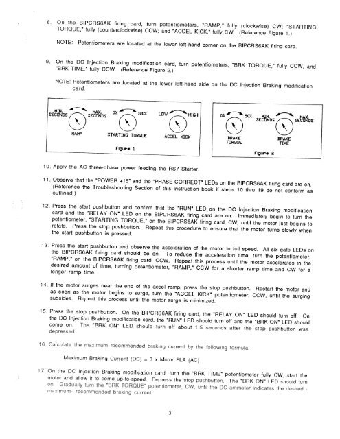
8. On the BIPCRS6AK firing card, turn potentiometers, “RAMP,” fully (clockwise) CW; “STARTING<br />
TORQUE,” fully (counterclockwise) CCW; and “ACCEL KICK,” fully CW. (Reference Figure 1.)<br />
NOTE: Potentiometers are located at the lower left-hand corner on the BIPCRS6AK firing card.<br />
9. On the DC Injection Braking modification card, turn potentiometers, “BRK TORQUE,” fully CCW, and<br />
“BRK TIME,” fully CCW. (Reference Figure 2.)<br />
NOTE: Potentiometers are located at the lower left-hand side on the DC Injection Braking modification<br />
card.<br />
MI MAX 07 1007 LOW<br />
SEC DS<br />
()SEcDt’4ns<br />
HIGH 0, 50/ SEiDS<br />
RAMP STARTING TORQUE ACCEL kICk BRAkE BRAKE<br />
TORQUE TIME<br />
Flgur. 1 FIgure 2<br />
1 0. Apply the AC three-phase power feeding the <strong>RS7</strong> Starter.<br />
()SE)S<br />
11. Observe that the “POWER +15” and the “PHASE CORRECT” LEDs on the BIPCRSSAK firing card are on.<br />
(Reference the Troubleshooting Section of this instruction book if steps 1 0 thru 19 do not conform as<br />
outlined.><br />
12. Press the start pushbutton and confirm that the “RUN” LED on the DC Injection Braking modification<br />
card and the “RELAY ON” LED on the BIPCRS6AK firing card are on. immediately begin to turn the<br />
potentiometer, “STARTING TORQUE,” on the BIPCRS6AK firing card, CW, until the motor just begins to<br />
rotate. Press the stop pushbutton. Repeat this procedure to ensure that the motor turns slowly when<br />
the start pushbutton is pressed.<br />
13, Press the start pushbutton and observe the acceleration of the motor to full speed. All six gate LEDs on<br />
the BIPCRS6AK firing card should be on. To reduce the acceleration time, turn the potentiometer,<br />
“RAMP,” on the BIPCRS6AK firing card, CCW. Repeat this process until the motor accelerates in the<br />
desired amount of time, turning potentiometer, “RAMP,” CCW for a shorter ramp time and CW for a<br />
longer ramp time.<br />
14, If the motor surges near the end of the accel ramp, press the stop pushbutton. Restart the motor and<br />
as soon as the motor begins to surge, turn the “ACCEL KICK” potentiometer, CCW, until the surging<br />
subsides. Repeat this process until the motor surge is minimized.<br />
15. Press the stop pushbutton. On the BIPCRS6AK firing card, the “RELAY ON” LED should turn off. On<br />
the DC Injection Braking modification card, the “RUN” LED should turn off and the “BRK ON” LED should<br />
come on. The “BRK ON” LED should turn off about 1.5 seconds after the stop pushbutton was<br />
depressed.<br />
1$ Calm late the maximum recommended braking current by the following formula:<br />
Maximum Braking Current (DC) = 3 x Motor FLA (AC)<br />
7. On the DC Injection Braking modification card, turn the “BRK TIME” potentiometer fully CW, start the<br />
motor and allow it to come up-to-speed. Depress the stop pushbutton. The “BRK ON LED should turn<br />
on. Gradually :urn the BRK TORQUE polenliometer. UW. until the DC ammeter indicates the des red -<br />
maximum- recommended braking current.