Design of an Autonomous Amphibious Robot for Surf - index - Naval ...
Design of an Autonomous Amphibious Robot for Surf - index - Naval ...
Design of an Autonomous Amphibious Robot for Surf - index - Naval ...

You also want an ePaper? Increase the reach of your titles
YUMPU automatically turns print PDFs into web optimized ePapers that Google loves.
Proceedings <strong>of</strong> the 2005 IEEE/ASME<br />
International Conference on Adv<strong>an</strong>ced Intelligent Mechatronics<br />
Monterey, Cali<strong>for</strong>nia, USA, 24-28 July, 2005<br />
<strong>Design</strong> <strong>of</strong> <strong>an</strong> <strong>Autonomous</strong> <strong>Amphibious</strong> <strong>Robot</strong> <strong>for</strong> <strong>Surf</strong> Zone Operations:<br />
Part II - Hardware, Control Implementation <strong>an</strong>d Simulation<br />
Richard Harkins, Jason Ward <strong>an</strong>d Ravi Vaidy<strong>an</strong>ath<strong>an</strong><br />
<strong>Autonomous</strong> <strong>Robot</strong>ics <strong>an</strong>d Systems Lab<br />
Departments <strong>of</strong> Physics <strong>an</strong>d Systems Engineering<br />
<strong>Naval</strong> Postgraduate School, Monterey, Cali<strong>for</strong>nia 93943<br />
Email: rharkins@nps.edu<br />
Abstract— This paper describes on-going work at The <strong>Naval</strong><br />
Postgraduate School (NPS) <strong>an</strong>d Case Western Reserve University<br />
(CWRU) to create <strong>an</strong> autonomous highly mobile amphibious<br />
robot. A first generation l<strong>an</strong>d-based prototype has been constructed<br />
<strong>an</strong>d field tested. This robot design, based on a tracked<br />
element, is capable <strong>of</strong> autonomous waypoint navigation, sel<strong>for</strong>ientation,<br />
obstacle avoid<strong>an</strong>ce, <strong>an</strong>d has the capacity to tr<strong>an</strong>smit<br />
sensor (visual) feedback. A water-resist<strong>an</strong>t second generation<br />
amphibious prototype design, based around the biologically<br />
inspired Whegs TM plat<strong>for</strong>m, has been completed. This design<br />
marries the unprecedented mobility <strong>of</strong> Whegs TM with the<br />
autonomous hardware <strong>an</strong>d control architectures implemented<br />
in the first generation prototype. Furthermore, we have also<br />
implemented a dynamic simulation capturing salient features<br />
<strong>of</strong> Whegs TM <strong>for</strong> testing <strong>of</strong> robotic locomotion capabilities. The<br />
integration <strong>of</strong> these elements will lay the foundation <strong>for</strong> the<br />
development <strong>of</strong> a new generation <strong>of</strong> highly mobile autonomous<br />
amphibious robots.<br />
Index Terms— Biologically inspired robotics, legged vehicles,<br />
micro-robots, reduced actuation.<br />
I. INTRODUCTION<br />
There has been signific<strong>an</strong>t interest in the development <strong>of</strong><br />
robots capable <strong>of</strong> autonomous amphibious operation within<br />
turbulent oce<strong>an</strong> surf zones. Of particular import<strong>an</strong>ce is the<br />
achievement <strong>of</strong> missions focused on the removal <strong>of</strong> shallowwater<br />
mines. Critical features include the ability to follow<br />
a search instruction pl<strong>an</strong>, rigorous terrain mobility, <strong>an</strong>d the<br />
capacity to classify <strong>an</strong>d map underwater mines <strong>an</strong>d other<br />
potential threats. Long term visions include the use <strong>of</strong> robots<br />
to scout <strong>an</strong>d map potential approach l<strong>an</strong>es <strong>for</strong> amphibious<br />
naval operations. Control, navigation, communication, obstacle<br />
avoid<strong>an</strong>ce, <strong>an</strong>d sensor payloads remain critical issues<br />
to be resolved <strong>for</strong> successful operation. Recent work [1], [2],<br />
[3] in this area has focused the construction <strong>of</strong> robots based<br />
on legged <strong>an</strong>d/or crawling elements to address these issues.<br />
A. Biologically Inspired Mech<strong>an</strong>isms<br />
Cockroaches have remarkable locomotion abilities. One<br />
solution to the problem <strong>of</strong> producing highly mobile amphibious<br />
robots is to design a vehicle with the mech<strong>an</strong>isms<br />
responsible <strong>for</strong> the mobility <strong>of</strong> a cockroach [5]. In studies<br />
<strong>of</strong> cockroach movement, we have noted the following locomotion<br />
principles. A cockroach has six legs, which support<br />
<strong>an</strong>d move its body. It typically walks <strong>an</strong>d runs in a tripod<br />
gait where the front <strong>an</strong>d rear legs on one side <strong>of</strong> the body<br />
0-7803-9046-6/05/$20.00 ©2005 IEEE.<br />
Alex<strong>an</strong>der S. Boxerbaum <strong>an</strong>d Roger D. Quinn<br />
Biologically Inspired <strong>Robot</strong>ics Lab<br />
Department <strong>of</strong> Mech<strong>an</strong>ical <strong>an</strong>d Aerospace Engineering<br />
Case Western Reserve University Clevel<strong>an</strong>d, Ohio 96678-2391<br />
Email: rdq@case.edu<br />
1465<br />
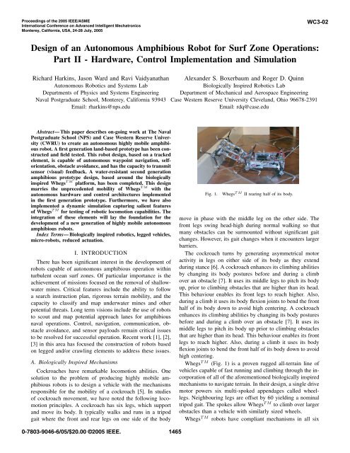
Fig. 1. Whegs TM II rearing half <strong>of</strong> its body.<br />
WC3-02<br />
move in phase with the middle leg on the other side. The<br />
front legs swing head-high during normal walking so that<br />
m<strong>an</strong>y obstacles c<strong>an</strong> be surmounted without signific<strong>an</strong>t gait<br />
ch<strong>an</strong>ges. However, its gait ch<strong>an</strong>ges when it encounters larger<br />
barriers.<br />
The cockroach turns by generating asymmetrical motor<br />
activity in legs on either side <strong>of</strong> its body as they extend<br />
during st<strong>an</strong>ce [6]. A cockroach enh<strong>an</strong>ces its climbing abilities<br />
by ch<strong>an</strong>ging its body postures be<strong>for</strong>e <strong>an</strong>d during a climb<br />
over <strong>an</strong> obstacle [7]. It uses its middle legs to pitch its body<br />
up, prior to climbing obstacles that are higher th<strong>an</strong> its head.<br />
This behaviour enables its front legs to reach higher. Also,<br />
during a climb it uses its body flexion joints to bend the front<br />
half <strong>of</strong> its body down to avoid high centering. A cockroach<br />
enh<strong>an</strong>ces its climbing abilities by ch<strong>an</strong>ging its body postures<br />
be<strong>for</strong>e <strong>an</strong>d during a climb over <strong>an</strong> obstacle [7]. It uses its<br />
middle legs to pitch its body up prior to climbing obstacles<br />
that are higher th<strong>an</strong> its head. This behaviour enables its front<br />
legs to reach higher. Also, during a climb it uses its body<br />
flexion joints to bend the front half <strong>of</strong> its body down to avoid<br />
high centering.<br />
Whegs TM (Fig. 1) is a proven rugged all-terrain line <strong>of</strong><br />
vehicles capable <strong>of</strong> fast running <strong>an</strong>d climbing through the incorporation<br />
<strong>of</strong> all <strong>of</strong> the a<strong>for</strong>ementioned biologically inspired<br />
mech<strong>an</strong>isms to navigate terrain. In their design, a single drive<br />
motor powers six multi-spoked appendages called wheellegs.<br />
Neighbouring legs are <strong>of</strong>fset by 60 yielding a nominal<br />
tripod gait. The spokes allow Whegs TM to climb over larger<br />
obstacles th<strong>an</strong> a vehicle with similarly sized wheels.<br />
Whegs TM robots have compli<strong>an</strong>t mech<strong>an</strong>isms in all six
Fig. 2. Whegs TM II flexing its body as it climbs over a curb<br />
<strong>of</strong> their axles. These mech<strong>an</strong>isms cause them to run in<br />
a nominal tripod gait, but passively adapt their gaits to<br />
irregular terrain. This compli<strong>an</strong>ce captures much <strong>of</strong> what the<br />
cockroach accomplishes with actions <strong>of</strong> its distal leg joints.<br />
The use <strong>of</strong> a single large drive motor provides a high powerto-weight<br />
ratio, making Whegs TM highly energetic, <strong>an</strong>d<br />
compli<strong>an</strong>t drive components enable passive gait adaptation<br />
over irregular terrain.<br />
Additionally, Whegs TM II, Fig. 1, incorporates a body<br />
flexion joint in addition to all <strong>of</strong> the mech<strong>an</strong>isms that were<br />
implemented in its precursor, Whegs TM I [8]. This actively<br />
controlled joint enables it to per<strong>for</strong>m both <strong>of</strong> the above<br />
posture ch<strong>an</strong>ges used by the cockroach, thereby improving<br />
its climbing ability as seen in Fig. 2.<br />
B. Objective<br />
We summarize on-going ef<strong>for</strong>ts at NPS <strong>an</strong>d CWRU aimed<br />
at the development <strong>of</strong> autonomous robotic devices capable<br />
<strong>of</strong> operations within the oce<strong>an</strong> surf zone. Part one <strong>of</strong> this<br />
project, the “<strong>Design</strong> <strong>of</strong> <strong>an</strong> <strong>Autonomous</strong> <strong>Amphibious</strong> <strong>Robot</strong><br />
<strong>for</strong> <strong>Surf</strong> Zone Operation: Part I, Mech<strong>an</strong>ical <strong>Design</strong> <strong>for</strong><br />
Mulit-Mode Mobility” [4], deals with the mech<strong>an</strong>ics <strong>of</strong> our<br />
plat<strong>for</strong>m. In this paper we report:<br />
• The development <strong>of</strong> a first generation autonomous l<strong>an</strong>dbased<br />
robot which will serve as a model <strong>for</strong> hardware<br />
<strong>an</strong>d control architectures <strong>for</strong> implementation on <strong>an</strong><br />
amphibious plat<strong>for</strong>m.<br />
• The development <strong>of</strong> a prototype mech<strong>an</strong>ical plat<strong>for</strong>m<br />
designed <strong>for</strong> arduous terrain locomotion ideally suited<br />
<strong>for</strong> amphibious operation.<br />
• The completion <strong>of</strong> a preliminary design integrating<br />
hardware <strong>an</strong>d control architectures onto the proposed<br />
amphibious locomotion plat<strong>for</strong>m.<br />
• The implementation <strong>of</strong> a dynamic simulation <strong>for</strong> robotic<br />
locomotive capability testing <strong>for</strong> design optimization.<br />
Our first goal was to develop a plat<strong>for</strong>m that would operate<br />
autonomously under waypoint navigation <strong>an</strong>d collision<br />
avoid<strong>an</strong>ce. This was done with a tracked vehicle. The <strong>Robot</strong><br />
would need to communicate in <strong>an</strong> IEEE 802.11 wireless<br />
environment, return visual data <strong>an</strong>d be able to respond to<br />
m<strong>an</strong>ual user input as required.<br />
1466<br />
Fig. 3. <strong>Robot</strong> Architecture<br />
II. FIRST GENERATION ARCHITECTURE<br />
A. Hardware<br />
Fig. 3 illustrates the architecture developed <strong>for</strong> the NPS<br />
autonomous robot. The heart <strong>of</strong> the system is based on the<br />
BL2000 WILDCAT microcontroller produced by Z-World.<br />
The BL2000 is programable in C <strong>an</strong>d has a development<br />
environment with a library <strong>of</strong> functions available <strong>for</strong> its<br />
interface ports <strong>an</strong>d Ethernet interface.<br />
The GPS <strong>an</strong>d compass components are connected via RS-<br />
232 ports. Ultrasonic sonars, with <strong>an</strong> <strong>an</strong>alog voltage output,<br />
are used <strong>for</strong> collision avoid<strong>an</strong>ce. The modem is a Netgear<br />
802.11g access point set up <strong>for</strong> UDP/IP communications.<br />
A st<strong>an</strong>dard RJ45 connection is used <strong>for</strong> this device. Motor<br />
control is realized with <strong>an</strong> <strong>an</strong>alog voltage output to a PWM<br />
circuit interfaced to <strong>an</strong> RC motor controller, this gives the<br />
robot differential motor control capabilty. Finally, our visual<br />
sensor is a st<strong>an</strong>dard DLink Web Cam, set up with a unique IP<br />
address <strong>an</strong>d connected directly to the modem. Table I gives<br />
a summary <strong>of</strong> the installed components.<br />
The components are powered by a 15 <strong>an</strong>d 6 volt (regulated)<br />
power-bus. These are supplied by a 15 volt, 11 amphour<br />
Lithium Polymer battery. The power bus <strong>an</strong>d major<br />
components are displayed in Fig. 4.<br />
The <strong>Robot</strong> was developed on a Foster-Miller Lemming<br />
tracked plat<strong>for</strong>m. Fig. 5 gives a <strong>for</strong>ward view illustrating the<br />
layout <strong>of</strong> the key sensors. The camera is mounted <strong>for</strong>ward <strong>of</strong><br />
the Garmin GPS receiver while the sonar array is mounted<br />
in the robot superstructure as shown.<br />
TABLE I<br />
ROBOT PARTS SUMMARY<br />
Components Model Vendor Comments<br />
Plat<strong>for</strong>m Lemming Foster Miller Differential Drive<br />
Micro-controller BL2000 Zworld Web Capable<br />
GPS GPS16 Garmin WAAS Capable<br />
Compass HMR2300 Honeywell +/- 1 Degree<br />
Sonar Ultra-30 Senix Corp 1-3 Meters<br />
Modem 802.11g Netgear Access-point
Fig. 4. NPS <strong>Autonomous</strong> Vehicle Power Bus [11]<br />
B. S<strong>of</strong>tware<br />
A 500 line C program <strong>an</strong>chors our system <strong>an</strong>d is compiled<br />
to flash ROM on the WILDCAT. Z-World Dynamic C<br />
<strong>of</strong>fers COSTATE capability <strong>an</strong>d is invoked in our program.<br />
COSTATES provide <strong>for</strong> the ability <strong>for</strong> functions to operate<br />
cooperatively during runtime. We found that this helped<br />
optimize our code by allowing functions to give up CPU<br />
cycles while waiting <strong>for</strong> a response or input from internal or<br />
external devices.<br />
The adv<strong>an</strong>tage is that the program uses CPU cycles more<br />
efficiently; the disadv<strong>an</strong>tage is that the programmer loses<br />
some control over function implementation.<br />
Algorithm logic is viewed in Fig. 6 <strong>an</strong>d COSTATE functions<br />
are listed. Any valid sonar contact is serviced as <strong>an</strong><br />
Interrupt Service Routine (ISR) <strong>an</strong>d control is passed to the<br />
Sonar COSTATE. You will notice that the M<strong>an</strong>ual Control<br />
COSTATE overrides all other COSTATES in the algorithm.<br />
C. Communications<br />
The wireless architecture was used <strong>for</strong> three purposes:<br />
1) Pass waypoint data prior to tr<strong>an</strong>sition to autonomous<br />
control<br />
2) Take m<strong>an</strong>ual control<br />
3) Send telemetry (GPS, Compass) <strong>an</strong>d/or error data to<br />
the remote wireless station<br />
Fig. 5. Front View<br />
1467<br />
Fig. 6. Algorithm In<strong>for</strong>mation Flow [9]<br />
Five UDP/IP communications sockets are established <strong>an</strong>d<br />
bound to the ports shown, Fig 6. Ports 4001 <strong>an</strong>d 4002 are set<br />
up one way from the remote station to the <strong>Robot</strong> <strong>an</strong>d ports<br />
4003, 4004 <strong>an</strong>d 4005 from the robot to the remote station.<br />
The UDP protocol is preferred because we do not need a<br />
three-way h<strong>an</strong>dshake <strong>for</strong> communication.<br />
A Java application, “MainApp”, was developed <strong>for</strong> the<br />
remote station, Fig. 7, <strong>for</strong> the user interface. “MainApp”,<br />
displays GPS, waypoint <strong>an</strong>d compass data (on the left), a<br />
field <strong>for</strong> a scaled chart (center), m<strong>an</strong>ual control interface <strong>an</strong>d<br />
a joystick pad (on the right). The scaled chart c<strong>an</strong> be grid<br />
locked to GPS coordinates. There<strong>for</strong>e selection <strong>of</strong> waypoints<br />
is simply a matter <strong>of</strong> double clicking a position on the chart<br />
<strong>an</strong>d sending the waypoint to the <strong>Robot</strong> via the “Send Route”<br />
button.<br />
Fig. 7. Example <strong>of</strong> the Main Application Interface showing the Icons<br />
<strong>for</strong> waypoints in red <strong>an</strong>d the robot in blue. Here we see the robot enroute<br />
waypoint 1 [10]<br />
In Fig. 7 we see the robot en-route waypoint 1. The chart<br />
is a scaled version <strong>of</strong> the NPS quadr<strong>an</strong>gle. Sp<strong>an</strong>agel Hall<br />
is the Science <strong>an</strong>d Engineering Building. You will notice<br />
that parsed GPS <strong>an</strong>d compass data are sent to the remote<br />
station <strong>an</strong>d displayed in the control p<strong>an</strong>el. This gives the<br />
observer a quick view <strong>of</strong> the status <strong>of</strong> the robot while in
auto (autonomous) mode, as indicated by the NAV MODE<br />
dialog box in fig 7. The icon <strong>for</strong> the robot is blue <strong>an</strong>d shows a<br />
heading leader based on compass input. You c<strong>an</strong> see that the<br />
heading is reported as 327 degrees magnetic. On this chart<br />
north is up, so we are confident that the heading is correct.<br />
Communications <strong>an</strong>d error data are displayed in the left<br />
h<strong>an</strong>d box. In<strong>for</strong>mation about sonar contacts <strong>an</strong>d waypoint<br />
navigation is also passed <strong>an</strong>d reported here.<br />
D. Control<br />
To give the robot the ability to control it’s heading during<br />
tr<strong>an</strong>sit <strong>an</strong>d turn rate during position corrections, a st<strong>an</strong>dard<br />
PID controller was invoked:<br />
� t<br />
S = Pce (t) + Ic<br />
t0<br />
de (t)<br />
e (t)dt + Dc<br />
dt<br />
The control signal S is sent to the pl<strong>an</strong>t from the compensator<br />
as illustrated in Fig. 8.<br />
For our architecture we chose to invoke the PID controller<br />
in s<strong>of</strong>tware. The gain coefficients Pc, Ic <strong>an</strong>d Dc where established<br />
empirically through field tests <strong>an</strong>d were normalized to<br />
one. We summed the PID outputs as follows:<br />
Where:<br />
S = SP + SI + SD<br />
SP = Pce (n)<br />
SI = Ic<br />
n=0<br />
5�<br />
e (n)<br />
(1)<br />
(2)<br />
(3)<br />
(4)<br />
SD = Dc(en+1 − en) (5)<br />
In our case, the error e (n) is the difference between desired<br />
<strong>an</strong>d actual heading in degrees, e (n) = θd −θa. The sensor <strong>for</strong><br />
the feedback is the digital magnetic compass. Upon receipt<br />
<strong>of</strong> waypoint latitude <strong>an</strong>d longitude coordinates, the robot<br />
calculates desired heading <strong>an</strong>d dist<strong>an</strong>ce <strong>an</strong>d then determines<br />
error. The receipt <strong>of</strong> a valid route-pl<strong>an</strong> also places the robot<br />
in autonomous mode. Error is passed to the compensator,<br />
invoked in s<strong>of</strong>tware, as a dynamic COSTATE. The output<br />
<strong>of</strong> the compensator is a number, S, that is interpreted as a<br />
motor control voltage <strong>an</strong>d is passed to the pl<strong>an</strong>t.<br />
Proportional gain, <strong>an</strong>d subsequently proportional control,<br />
dominates our equation. Little velocity feedback is required<br />
since our plat<strong>for</strong>m moves slowly. Integral control is needed<br />
Desired<br />
Heading<br />
+<br />
-<br />
e<br />
Compensator<br />
S<br />
PID Controller<br />
Actual<br />
Heading<br />
Digital<br />
Compass<br />
Fig. 8. Functional Control Loop<br />
Pl<strong>an</strong>t<br />
Motors<br />
Feedback<br />
Course<br />
1468<br />
to compensate <strong>for</strong> a DC <strong>of</strong>fset that we <strong>of</strong>ten encounter as<br />
we near our desired heading. The unit is relatively heavy<br />
such that proportional control inputs from the compensator<br />
are not enough to overcome ground friction, motor friction<br />
<strong>an</strong>d plat<strong>for</strong>m inertia. We needed to integrate over at least five<br />
program time counts to overcome this problem.<br />
E. Results<br />
The hardware, <strong>an</strong>d control architecture provided the robot<br />
with the ability to conduct waypoint navigation <strong>an</strong>d collision<br />
avoid<strong>an</strong>ce in the field. Fig. 9 shows the robot approaching<br />
from the right, enroute a waypoint avoiding <strong>an</strong> obstacle<br />
(person) by m<strong>an</strong>euvering to the right.<br />
Fig. 9. The <strong>Robot</strong> Avoids<br />
However the tracked vehicle does not operate nicely in<br />
rugged terrain environments. It is relatively heavy <strong>an</strong>d slow<br />
<strong>an</strong>d has difficulty traversing obstacles. As a Consequence, it<br />
has a tendency to high center on relatively small protrusions.<br />
There<strong>for</strong>e, this autonomous functionality will need to be<br />
used in a more versatile <strong>an</strong>d rugged Plat<strong>for</strong>m <strong>an</strong>d is pl<strong>an</strong>ned<br />
<strong>for</strong> the Whegs TM IV plat<strong>for</strong>m.<br />
III. AMPHIBIOUS WHEGS TM DESIGN<br />
WhegsTM IV is designed to have a fully enclosed chassis<br />
that is waterpro<strong>of</strong> in up to 40 feet <strong>of</strong> water <strong>an</strong>d dirt pro<strong>of</strong> on<br />
l<strong>an</strong>d. This will allow the robot to autonomously navigate the<br />
oce<strong>an</strong> floor, surf zone <strong>an</strong>d beach with little or no low-level<br />
control.<br />
Previous WhegsTM designs [8] have <strong>an</strong> open-frame,<br />
where all components are attached to one <strong>of</strong> the cross<br />
members. This allows <strong>for</strong> a lightweight chassis that is easy to<br />
service Fig. 10. However, dirt <strong>an</strong>d debris c<strong>an</strong> clog the drive<br />
train <strong>an</strong>d damage the electronic components. WhegsTM IV is<br />
completely encased, keeping dirt as well as water out. Each<br />
body segment is constructed from four aluminum side p<strong>an</strong>els<br />
<strong>an</strong>d carbon fiber tops <strong>an</strong>d bottoms. Each set <strong>of</strong> four side<br />
p<strong>an</strong>els is sealed to itself using a silicone liquid gasket, while<br />
the carbon fiber p<strong>an</strong>els are sealed to the side p<strong>an</strong>els using<br />
rubber gaskets. This will allow the robot to be easily serviced<br />
by removing the carbon fiber p<strong>an</strong>els without breaking the<br />
seals between the side p<strong>an</strong>els.<br />
Special consideration is needed to accommodate the drive<br />
train as it passes through the body joint. The chain <strong>an</strong>d<br />
sprocket running from the middle axle to the front axle needs
Fig. 10. Whegs TM IV concept rendering<br />
to be encased <strong>an</strong>d sealed. There also has to be a way to<br />
actuate the body joint. Both <strong>of</strong> these goals are accomplished<br />
by extending the case <strong>of</strong> the front body segment around<br />
the whole chain <strong>an</strong>d sprocket that connects the two body<br />
segments. This protrusion <strong>of</strong> the case then mounts to the rear<br />
body segment at the middle axle in a coaxial arr<strong>an</strong>gement.<br />
The outer axle actuates the body joint <strong>an</strong>d the inner axle<br />
attaches to the sprocket <strong>an</strong>d chain to deliver torque to the<br />
front wheel-legs. By keeping all connections axial in nature,<br />
a st<strong>an</strong>dard rotary seal c<strong>an</strong> be used to keep water <strong>an</strong>d dust<br />
out.<br />
Rotary axles must also penetrate the body <strong>of</strong> the robot<br />
in six other places, one <strong>for</strong> each wheel-leg. Several rotary<br />
shaft seals are in consideration <strong>for</strong> this task. One possibility<br />
is a mech<strong>an</strong>ical seal, with two mating parts rotating against<br />
each other, one mounted to the shaft <strong>an</strong>d the other mounted<br />
to the body. Another possibility is a single or double Oring<br />
seal, which c<strong>an</strong> be specialized <strong>for</strong> positive <strong>an</strong>d negative<br />
pressure, but are more susceptible to leaking as grease wears<br />
<strong>of</strong>f. Finally, a spring loaded graphite ring c<strong>an</strong> mate with a<br />
polished shaft. All <strong>of</strong> these solutions may be complimented<br />
by pressurizing the hull to push air out, instead <strong>of</strong> pulling<br />
water in, if a leak occurs. Steering push rods that also<br />
penetrate the body <strong>of</strong> the robot <strong>an</strong>d must be sealed. Since<br />
they have a limited r<strong>an</strong>ge <strong>of</strong> motion, a flexible rubber bellows<br />
c<strong>an</strong> be perm<strong>an</strong>ently affixed to the push rod <strong>an</strong>d housing.<br />
Because the robot is intended to be autonomous with little<br />
or no knowledge <strong>of</strong> small obstacles in its immediate path, it<br />
is best if these obstacles c<strong>an</strong> be surmounted passively whenever<br />
possible. The a<strong>for</strong>ementioned strategies implemented in<br />
Whegs TM II are useful to this end. Whegs TM IV has several<br />
adv<strong>an</strong>cements to this end.<br />
A body joint on previous Whegs TM allowed the robot to<br />
climb larger objects by giving the front wheel-legs higher<br />
reach <strong>an</strong>d by preventing high centering. However, several<br />
designs have not survived field testing. The first version<br />
<strong>of</strong> Whegs TM ł with a body joint used a large backdrivable<br />
servo, which allowed the motor to absorb some <strong>of</strong> the<br />
shock <strong>of</strong> impact, but const<strong>an</strong>t current draw quickly drained<br />
the batteries. To remedy this, Whegs TM III used a nonbackdrivable<br />
worm gear. However, the teeth <strong>of</strong> the gear<br />
1469<br />
Fig. 11. Whegs TM IIII body joint drive shaft (right) <strong>an</strong>d middle axle (left)<br />
in coaxial arr<strong>an</strong>gement<br />
sheared <strong>of</strong>f under impact loading. The Whegs TM IV body<br />
joint has a worm gear in series with the tr<strong>an</strong>smission <strong>an</strong>d<br />
motor, like Whegs TM III. However, the tooth face is twice<br />
as large <strong>an</strong>d has been designed to withst<strong>an</strong>d the frequent<br />
impact loads the robot experiences, Fig. 11.<br />
The Interior view <strong>of</strong> component layout is seen in Fig 12.<br />
Whegs TM IV will include space <strong>for</strong> the components used<br />
by the NPS first generation autonomous vehicle. With the<br />
exception <strong>of</strong> the motor <strong>an</strong>d torsion devices, the front compartment<br />
is left free <strong>for</strong> electronics <strong>an</strong>d sensors. Batteries,<br />
speed controllers, the body joint mech<strong>an</strong>ism <strong>an</strong>d motor, <strong>an</strong>d<br />
additional electronics are stored in the rear body segment.<br />
With a microprocessor, GPS, compass <strong>an</strong>d three sonar sensors,<br />
there is still ample room <strong>for</strong> additional equipment.<br />
IV. SIMULATION FOR DESIGN OPTIMIZATION<br />
Finally, we have constructed a basic environment such that<br />
our amphibious WhegsTM design may be tested dynamically<br />
in simulation prior to construction. The results <strong>of</strong> one simulation<br />
run, in this environment, are shown in Fig. 13. In this<br />
simulation, a quadruped robot driven by 4 spoke wheel-legs<br />
approaches a plateau which it must climb. The height <strong>of</strong> the<br />
plateau in this simulation is exactly equal to the height <strong>of</strong><br />
each wheel-leg (measured from the geometric center). The<br />
Fig. 12. Another innovation in Whegs TM IV is a clear acrylic front<br />
p<strong>an</strong>el. This makes it possible to mount infrared sensors or a video camera<br />
internally in <strong>an</strong> area directly adjacent to the main electronics compartment.<br />
The rounded shape <strong>of</strong> the front P<strong>an</strong>el will have good hydrodynamic<br />
characteristics <strong>an</strong>d will also allow it to push up <strong>an</strong>d over irregularly shaped<br />
obstacles
Fig. 13. Simulation<br />
body <strong>of</strong> the robot was modeled as a rod attached to 2 revolute<br />
joints, each <strong>of</strong> which was connected to a shaft driving the<br />
wheel-legs. The weight <strong>of</strong> the rod was 10 kg representing<br />
the robot sensor payload, motors, <strong>an</strong>d chassis.<br />
The weight <strong>of</strong> each shaft was 1 kg, <strong>an</strong>d the weight <strong>of</strong><br />
each wheel-leg was 300 grams. As with the actual robot, each<br />
wheel-leg was also equipped with a compli<strong>an</strong>t mech<strong>an</strong>ism, in<br />
the <strong>for</strong>m <strong>of</strong> a torsional spring with a const<strong>an</strong>t <strong>of</strong> 0.2 N-m/deg.<br />
The robot was also designed to run in a diagonal gait where<br />
each wheel-leg was moving in phase with the wheel-leg<br />
diagonally opposite itself. From top to bottom, each snapshot<br />
in Fig. 13 shows phases <strong>of</strong> the dynamic simulation:<br />
• The robot in motion at the beginning <strong>of</strong> the simulation<br />
• The robot just prior to reaching the vertical step to the<br />
plateau. (Note: The robot has not reached the plateau,<br />
<strong>an</strong>d is still moving in a diagonal gait, as c<strong>an</strong> be seen<br />
from the gait.)<br />
• The robot is beginning to climb the step<br />
These results clearly demonstrate the capacity <strong>of</strong><br />
Whegs TM to passively adjust its gait to arduous terrain. This<br />
simulation testbed will be used extensively to dynamically<br />
examine the locomotive capability <strong>of</strong> our design to insure<br />
proper functionality <strong>for</strong> all m<strong>an</strong>ner <strong>of</strong> amphibious operations.<br />
1470<br />
V. CONCLUSIONS AND FUTURE WORK<br />
A. Conclusions<br />
These design innovations will allow WhegsTM IV to navigate<br />
on rough terrain <strong>an</strong>d under water to accomplish tasks<br />
with little or no low-level control. This will greatly simplify<br />
the autonomous control problem <strong>an</strong>d give the vehicle a<br />
versatility that no amphibious robot has yet enjoyed.<br />
B. Future Work<br />
A Dead Reckoning (DR) capability will be added to the<br />
system in the near future. Current position in<strong>for</strong>mation is<br />
the sole result <strong>of</strong> the ability to receive accurate GSP data.<br />
However, GPS c<strong>an</strong>not <strong>an</strong>d should not be relied upon as the<br />
only source <strong>for</strong> position. The concept <strong>of</strong> operations <strong>for</strong> the<br />
plat<strong>for</strong>m includes some time at, near or under the water <strong>an</strong>d<br />
would preclude GPS reception.<br />
VI. ACKNOWLEDGMENTS<br />
The authors gratefully acknowledge the contribution <strong>of</strong> the<br />
m<strong>an</strong>y students at the <strong>Naval</strong> Postgraduate school <strong>an</strong>d Case<br />
Western Reserve University who have contributed to this<br />
project over the past two years.<br />
REFERENCES<br />
[1] Bernstein, C., Connolly, M., Gavrilash, M., Kucik, D., Threatt, S.,<br />
“Demonstration <strong>of</strong> <strong>Surf</strong>Zone Crawlers: Results from AUV Fest 01”,<br />
<strong>Surf</strong> Zone Crawler Group, <strong>Naval</strong> <strong>Surf</strong>ace Warfare Center, P<strong>an</strong>ama City,<br />
FL, 2001<br />
[2] Prahacs, C., Saunders, A., Smith, M., McMordie, D., Buehler, M.,<br />
“Towards Legged <strong>Amphibious</strong> Mobile <strong>Robot</strong>ics, The Inaugural C<strong>an</strong>adi<strong>an</strong><br />
<strong>Design</strong> Engineering Network (CDEN) <strong>Design</strong> Conference, July,<br />
2004.<br />
[3] i<strong>Robot</strong> Corporation, Ariel <strong>Robot</strong>, http://www.irobot.com/home.cfm<br />
[4] Boxerbaum, Alex<strong>an</strong>der S., Werk, Philip, Quinn, Roger D.,<br />
Vaidy<strong>an</strong>ath<strong>an</strong>, Ravi, “<strong>Design</strong> <strong>of</strong> <strong>an</strong> <strong>Autonomous</strong> <strong>Amphibious</strong> <strong>Robot</strong><br />
<strong>for</strong> <strong>Surf</strong> Zone Operation: Part I, Mech<strong>an</strong>ical <strong>Design</strong> <strong>for</strong> Mulit-Mode<br />
Mobility” submission <strong>for</strong> IEEE ASME AIM2005 conference, Monterey,<br />
Cali<strong>for</strong>nia, USA, 24-28 July 2005.<br />
[5] Ritzm<strong>an</strong>n, R.E., Rice, C.M., Pollack, A.J., Ridgel, A.L. Kingsley, D.A.<br />
<strong>an</strong>d Quinn, R.D. (2001) Roles <strong>of</strong> descending control in locomotion<br />
through complex terrain. Congress <strong>of</strong> Neuroethology. 6, pg. 234.<br />
[6] Watson, J.T., Ritzm<strong>an</strong>n, R.E., Zill, S.N., Pollack, A.J. (2002) Control<br />
<strong>of</strong> obstacle climbing in the cockroach, Blaberus discoidalis: I. Kinematics,<br />
J. Comp. Physiology Vol. 188: 39-53.<br />
[7] Yoneda, K. (2001). <strong>Design</strong> <strong>of</strong> non-bio-mimetic walker with fewer<br />
actuators. Proceedings <strong>of</strong> 4th Int. Conf. On Climbing <strong>an</strong>d Walking<br />
<strong>Robot</strong>s (CLAWAR), From Biology to Industrial Applications, edited<br />
by K. Berns <strong>an</strong>d R. Dillm<strong>an</strong>n, Pr<strong>of</strong>essional Engineering Publishing,<br />
pp. 115-126.<br />
[8] Quinn, R.D., Kingsley, D.A., Offi, J.T. <strong>an</strong>d Ritzm<strong>an</strong>n, R.E., (2002),<br />
Improved mobility through abstracted biological principles, IEEE<br />
Int. Conf. On Intelligent <strong>Robot</strong>s <strong>an</strong>d Systems (IROS02), Laus<strong>an</strong>ne,<br />
Switzerl<strong>an</strong>d<br />
[9] Niles, Se<strong>an</strong>, et. al., “SE4015 Course Presentation”, <strong>Naval</strong> Postgraduate<br />
School, September 2004<br />
[10] Uz<strong>an</strong>, Kubilay, et al., “SE4015 Course Presentation”, <strong>Naval</strong> Postgraduate<br />
School, September 2003<br />
[11] Felekoglu, Oktay, et al., “SE4015 Course Presentation”, <strong>Naval</strong> Postgraduate<br />
School, September 2004