Method, Accuracy and Limitation of Computer Interaction in ... - Lirmm
Method, Accuracy and Limitation of Computer Interaction in ... - Lirmm
Method, Accuracy and Limitation of Computer Interaction in ... - Lirmm

Create successful ePaper yourself
Turn your PDF publications into a flip-book with our unique Google optimized e-Paper software.
33rd Annual International Conference <strong>of</strong> the IEEE EMBS<br />
Boston, Massachusetts USA, August 30 - September 3, 2011<br />
Abstract — This article describes a new <strong>in</strong>teraction device<br />
for surgical navigation systems – the so-called navigation<br />
mouse system. The idea is to use a tracked <strong>in</strong>strument <strong>of</strong> a<br />
surgical navigation system like a po<strong>in</strong>ter to control the<br />
s<strong>of</strong>tware. The new <strong>in</strong>teraction system extends exist<strong>in</strong>g<br />
navigation systems with a microcontroller-unit. The<br />
microcontroller-unit uses the exist<strong>in</strong>g communication l<strong>in</strong>e to<br />
extract the needed 3D-<strong>in</strong>formation <strong>of</strong> an <strong>in</strong>strument to<br />
calculate positions analogous to the PC mouse cursor <strong>and</strong> click<br />
events. These positions <strong>and</strong> events are used to manipulate the<br />
navigation system. In an experimental setup the reachable<br />
accuracy with the new mouse system is shown.<br />
I<br />
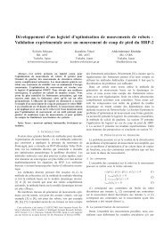
<strong>Method</strong>, accuracy <strong>and</strong> limitation <strong>of</strong> computer <strong>in</strong>teraction <strong>in</strong> the<br />
operat<strong>in</strong>g room by a navigated surgical <strong>in</strong>strument<br />
Florian Hurka, Thomas Wenger, Sebastian He<strong>in</strong><strong>in</strong>ger, Tim C. Lueth, Member, IEEE<br />
I. INTRODUCTION<br />
N modern operat<strong>in</strong>g rooms navigation systems have been<br />
used for more than 20 years to assist the surgeon to orient<br />
<strong>in</strong> the <strong>in</strong>terior <strong>of</strong> the patient even under difficult or nonexistent<br />
visibility conditions [1]. If the surgeon operates<br />
<strong>in</strong>side the body us<strong>in</strong>g surgical <strong>in</strong>struments, he needs<br />
<strong>in</strong>formation about the precise position <strong>and</strong> orientation <strong>of</strong> the<br />
<strong>in</strong>struments. The st<strong>and</strong>ard tools to see where the <strong>in</strong>struments<br />
are located with<strong>in</strong> the body are microscopes <strong>and</strong><br />
endoscopes. A navigation system can be used to visualize<br />
the relative position <strong>of</strong> the <strong>in</strong>struments accord<strong>in</strong>g to<br />
preoperative image data such as CT/DVT or MRI data.<br />
Surgical navigation systems are computer-based assistance<br />
systems, consist<strong>in</strong>g <strong>of</strong> a computer with monitor, a stereo<br />
camera <strong>and</strong> <strong>in</strong>struments with attached measurement markers<br />
[2]. Preoperative image data (usually CT data) are loaded<br />
<strong>in</strong>to the navigation system. The measurement system, the<br />
stereo camera, is able to analyze the position <strong>of</strong> the<br />
measur<strong>in</strong>g markers on the <strong>in</strong>struments. After a registration<br />
process, the position <strong>and</strong> orientation <strong>of</strong> the <strong>in</strong>struments can<br />
be displayed relatively to the image data. Thus, the distances<br />
can be measured or the surgeon can be warned if he comes<br />
Manuscript received on March 26, 2011.<br />
The presented work was performed at the Institute for Micro Technology<br />
<strong>and</strong> Medical Device Technology at the Technische Universität München,<br />
Garch<strong>in</strong>g, Germany <strong>and</strong> the company ERGOSURG GmbH, Isman<strong>in</strong>g,<br />
Germany.<br />
Florian Hurka <strong>and</strong> Sebastian He<strong>in</strong><strong>in</strong>ger are PhD-students at the Institute<br />
for Micro Technology <strong>and</strong> Medical Device Technology at the Technische<br />
Universität München <strong>and</strong> ERGOSURG GmbH, Isman<strong>in</strong>g, Germany (e-mail:<br />
florian.hurka@ergosurg.com, sebastian.he<strong>in</strong><strong>in</strong>ger@ergosurg.com)<br />
Thomas Wenger is PhD-student at the Universität Leipzig <strong>and</strong><br />
ERGOSURG GmbH, Isman<strong>in</strong>g, Germany (e-mail:<br />
thomas.wenger@ergosurg.com)<br />
Tim C. Lueth is director <strong>of</strong> the Institute for Micro Technology <strong>and</strong><br />
Medical Device Technology at the Technische Universität München,<br />
Garch<strong>in</strong>g, Germany (e-mail: tim.lueth@tum.de).<br />
978-1-4244-4122-8/11/$26.00 ©2011 IEEE 2144<br />
too close to a risk structure.<br />
To work with a computer-based system like the<br />
navigation system the user has to <strong>in</strong>teract with the graphical<br />
user <strong>in</strong>terface <strong>of</strong> the s<strong>of</strong>tware. Subsequent <strong>in</strong>teractions need<br />
to be h<strong>and</strong>led:<br />
1) Load<strong>in</strong>g <strong>of</strong> patient image data sets<br />
2) Sett<strong>in</strong>g <strong>and</strong> shift<strong>in</strong>g <strong>of</strong> l<strong>and</strong>marks (registration po<strong>in</strong>ts) <strong>in</strong><br />
the image data<br />
3) Select menu items <strong>in</strong> the navigation s<strong>of</strong>tware<br />
4) Confirm comm<strong>and</strong>s<br />
5) Measure anatomic structures <strong>in</strong> the patient data<br />
The typical <strong>in</strong>teraction concepts with today’s navigation<br />
systems <strong>of</strong> the market leaders (Medtronic, Bra<strong>in</strong>LAB, B.<br />
Braun Melsungen, Aesculap, GE Healthcare, KARL<br />
STORZ Endoskope, RoboDent) are:<br />
Indirect <strong>in</strong>teraction: The systems are manipulated by<br />
<strong>in</strong>struct<strong>in</strong>g the <strong>in</strong>teractions to non-sterile surgical staff [3].<br />
Keyboard <strong>and</strong> mouse: For a long time, navigation systems<br />
have been controlled by a keyboard covered with a sterile<br />
bag <strong>and</strong> a mouse cleaned by a dis<strong>in</strong>fectant wipe. The<br />
keyboard is most appropriate for writ<strong>in</strong>g str<strong>in</strong>gs. The mouse<br />
is one <strong>of</strong> the most established <strong>and</strong> best <strong>in</strong>put devices for the<br />
two-dimensional <strong>in</strong>teraction with s<strong>of</strong>tware <strong>in</strong>terfaces.<br />
Touchscreen: Many <strong>of</strong> the current systems use touchscreens.<br />
These are covered with a sterile bag. Thus, the surgeon can<br />
work with the system <strong>in</strong> the range <strong>of</strong> his arms. One example<br />
is the Navigation Panel Unit (NPU) <strong>of</strong> the company KARL<br />
STORZ [4].<br />
FESS-Frame: This product sold by Medtronic uses a<br />
navigated board which allows the <strong>in</strong>teraction <strong>of</strong> medical<br />
navigation systems. This approach was demonstrated <strong>in</strong><br />
1997 <strong>in</strong> [5]. Here, a control board with various control icons<br />
is used. The board itself, which is extended with<br />
measurement markers, is tracked by the navigation camera.<br />
By this means, the position <strong>of</strong> the board <strong>and</strong> thus the<br />
position <strong>of</strong> the icon on the board are known <strong>in</strong> space. If the<br />
control board is affected by a navigated <strong>in</strong>strument on the<br />
surface, the pre-def<strong>in</strong>ed action accord<strong>in</strong>g to the touched icon<br />
which is labeled on the board is executed.<br />
Voicecontrol: Another approach is the <strong>in</strong>teraction by voice<br />
control as described <strong>in</strong> [6]. A headset is used for this<br />
<strong>in</strong>teraction. The speaker navigates with pre-def<strong>in</strong>ed voice<br />
comm<strong>and</strong>s through the menus <strong>of</strong> the s<strong>of</strong>tware. The possible<br />
voice comm<strong>and</strong>s are visualized by the s<strong>of</strong>tware on a monitor<br />
to provide a visual feedback on the selection. A<br />
commercially available product is VOICE1® by KARL<br />
STORZ. It translates the voice comm<strong>and</strong>s <strong>and</strong> puts them on
a bus, the so-called SCB (StorzCommunicationBus).<br />
Gesture recognition: A gesture recognition system for the OR<br />
<strong>in</strong>terprets gestures [7-9]. These gestures can control the user<br />
<strong>in</strong>terface <strong>of</strong> the s<strong>of</strong>tware.<br />
WiiMote: In current research projects, systems are known as<br />
described <strong>in</strong> [10] <strong>and</strong> [11]. In one project, a WiiMote is used<br />
for <strong>in</strong>teraction purposes with the IPA (Intraoperative<br />
Plann<strong>in</strong>g Assistant). The WiiMote is a wireless bluetooth<br />
po<strong>in</strong>t<strong>in</strong>g device <strong>in</strong>tended for controll<strong>in</strong>g the Wii, the gam<strong>in</strong>g<br />
console by N<strong>in</strong>tendo. The WiiMote uses an optical sensor as<br />
well as an acceleration sensor for motion analysis. This<br />
WiiMote is read directly <strong>in</strong>to the IPA system without us<strong>in</strong>g<br />
the Wii console itself. The IPA-system <strong>in</strong>terprets the motion<br />
<strong>in</strong>formation <strong>of</strong> the WiiMote. So the WiiMote can be used for<br />
<strong>in</strong>teraction with the system as a po<strong>in</strong>t<strong>in</strong>g device.<br />
These approaches are still fac<strong>in</strong>g some problems. In case<br />
<strong>of</strong> <strong>in</strong>teraction with a computer mouse <strong>and</strong> keyboard it is a<br />
problem to f<strong>in</strong>d a suitable underlay with<strong>in</strong> the range <strong>of</strong> the<br />
surgeon.<br />
The use <strong>of</strong> the touch screen is complicated by the sterile<br />
cover [7]. The image quality <strong>of</strong> the screen is affected due to<br />
the lesser transparency <strong>of</strong> the bag. To <strong>in</strong>teract with a touch<br />
screen it must be located with<strong>in</strong> the range <strong>of</strong> the surgeons.<br />
This is not always possible due to shortage <strong>of</strong> space <strong>in</strong> the<br />
operat<strong>in</strong>g room.<br />
When us<strong>in</strong>g the FESS-frame, the board is required as an<br />
additional tracked <strong>in</strong>strument. Moreover, the board has to be<br />
sterilized.<br />
An <strong>in</strong>direct <strong>in</strong>teraction by <strong>in</strong>struct<strong>in</strong>g the OR-team can be<br />
afflicted with errors <strong>and</strong> delays [3].<br />
Accord<strong>in</strong>g to the gesture recognition approach [7-9] the<br />
currently used <strong>in</strong>strument must be set aside <strong>and</strong> the arm must<br />
be lifted to achieve the desired action. This system also<br />
requires an <strong>in</strong>stallation <strong>of</strong> another camera for gesture<br />
recognition <strong>in</strong> the operat<strong>in</strong>g room.<br />
In case <strong>of</strong> us<strong>in</strong>g the WiiMote accord<strong>in</strong>g to [10] <strong>and</strong> [11]<br />
the target monitor must be upgraded with a sensorbar, an<br />
array <strong>of</strong> <strong>in</strong>frared LEDs. Thus, the visualization <strong>and</strong><br />
<strong>in</strong>teraction is l<strong>in</strong>ked to this monitor. Moreover, additional<br />
s<strong>of</strong>tware must be <strong>in</strong>stalled on the target system.<br />
This article describes an accuracy study with a new<br />
<strong>in</strong>teraction system for surgical navigation systems which<br />
uses an already exist<strong>in</strong>g <strong>in</strong>strument for <strong>in</strong>teraction. This<br />
<strong>in</strong>strument is <strong>of</strong>ten used dur<strong>in</strong>g the surgery. The <strong>in</strong>teraction<br />
with the navigation system can directly be carried out by the<br />
surgeon himself without any additional <strong>in</strong>struments. The<br />
system is an external, small (about 8 cm × 5 cm × 4 cm)<br />
controller based st<strong>and</strong>-alone module. One advantage is that<br />
the orig<strong>in</strong>al s<strong>of</strong>tware runn<strong>in</strong>g on the navigation system does<br />
not have to be changed. Another advantage is that this<br />
<strong>in</strong>strument is a purchased part <strong>of</strong> the navigation system.<br />
Thus, the sterilizability <strong>of</strong> the <strong>in</strong>struments is assured by the<br />
manufacturer. To ensure the usability it should be possible<br />
to click buttons on the screen. Therefore, the new <strong>in</strong>teraction<br />
system is experimentally compared with a touch screen.<br />
2145<br />
II. MATERIAL AND METHODS<br />
A new <strong>in</strong>teraction device (NMS – navigated mouse<br />
system) for navigation systems <strong>and</strong> accuracy study are<br />
presented <strong>in</strong> the subsequent sections.<br />
A. The navigation system upgraded with the new<br />
<strong>in</strong>teraction system<br />
The new system uses a commercially available navigation<br />
system as described by [4]. Fig. 1 shows the typical<br />
schematic structure <strong>of</strong> a navigation system. This navigation<br />
system uses a PC as a navigation computer. The graphical<br />
user <strong>in</strong>terface is displayed on a monitor. This navigation<br />
computer is connected to the navigation camera by a<br />
communication cable. There are several tracked <strong>in</strong>struments<br />
available for the navigation system. The position <strong>and</strong><br />
orientation <strong>of</strong> these <strong>in</strong>struments can be tracked via the<br />
attached measurement markers. The <strong>in</strong>formation <strong>of</strong> position<br />
<strong>and</strong> orientation is transferred to the navigation computer via<br />
a communication cable. An <strong>in</strong>put device is connected to the<br />
navigation computer. Mice or touchscreens are typical <strong>in</strong>put<br />
devices for navigation systems.<br />
Fig. 1: Schematic structure <strong>of</strong> a surgical navigation system<br />
The new <strong>in</strong>put device is <strong>in</strong>tegrated <strong>in</strong>to the navigation<br />
system as a module <strong>in</strong>stead <strong>of</strong> or <strong>in</strong> addition to the normal<br />
<strong>in</strong>put device (Fig. 2). Therefore, a further process<strong>in</strong>g unit, a<br />
processor, is connected to the communication l<strong>in</strong>e between<br />
the navigation computer <strong>and</strong> navigation camera. This<br />
process<strong>in</strong>g unit can listen to the communication <strong>of</strong> the<br />
navigation camera <strong>and</strong> the navigation system. However, the<br />
process<strong>in</strong>g unit is also able to write data to the camera. Thus,<br />
the camera can be <strong>in</strong>itialized by the controller-unit, <strong>and</strong> the<br />
camera can be used for <strong>in</strong>teraction before the navigation is<br />
started on the navigation computer. The unit features,<br />
alongside the <strong>in</strong>terfaces for the communication l<strong>in</strong>e to the<br />
camera <strong>and</strong> to the navigation computer, an additional<br />
<strong>in</strong>terface for transmitt<strong>in</strong>g mouse data to the navigation<br />
computer. This additional <strong>in</strong>terface is a HID-conform USBconnection.<br />
An advantage <strong>of</strong> the USB-HID is that this is a<br />
st<strong>and</strong>ardized plug’n’play <strong>in</strong>terface, which does not need any<br />
s<strong>of</strong>tware changes. For this work the NMS is connected to the<br />
navigation system for <strong>in</strong>teraction. However, the USB<strong>in</strong>terface<br />
could also be connected to any other computerbased<br />
system for <strong>in</strong>teraction. For the new <strong>in</strong>teraction method<br />
a tracked <strong>in</strong>strument is used. This tracked <strong>in</strong>strument is an
elongated po<strong>in</strong>t<strong>in</strong>g <strong>in</strong>strument, the probe, with three attached<br />
measurement markers <strong>in</strong> a predef<strong>in</strong>ed geometry. The probe<br />
is an already exist<strong>in</strong>g <strong>in</strong>strument which is always used for a<br />
navigated surgery. Its usual use is to match the anatomic<br />
surface <strong>of</strong> the patient with the CT-data <strong>and</strong> to check<br />
<strong>in</strong>traoperative the progress <strong>of</strong> preoperative planed surgery.<br />
Fig. 2: Schematic structure <strong>of</strong> the navigated mouse system <strong>in</strong>tegrated<br />
<strong>in</strong> the navigation system<br />
The graphical user <strong>in</strong>terface <strong>of</strong> the navigation system is<br />
visualized on a monitor. In navigation mode the <strong>in</strong>struments<br />
which are located <strong>in</strong> the field <strong>of</strong> view <strong>of</strong> the camera can be<br />
tracked. The navigation camera recognizes the pre-def<strong>in</strong>ed<br />
geometry <strong>of</strong> the measurement markers <strong>of</strong> the probe <strong>and</strong><br />
calculates the 3D-position <strong>and</strong> orientation <strong>of</strong> the <strong>in</strong>strument.<br />
The 3D-<strong>in</strong>formation is transferred <strong>in</strong> form <strong>of</strong> a quaternion<br />
<strong>and</strong> a translation vector to the navigation computer. This<br />
quaternion <strong>and</strong> the translation vector are also available for<br />
the processor unit which is listen<strong>in</strong>g on the communication<br />
l<strong>in</strong>e. This quaternion <strong>and</strong> the translation vector are<br />
transformed <strong>in</strong>to homogeneous coord<strong>in</strong>ates. If certa<strong>in</strong><br />
markers can not be associated with any <strong>in</strong>strument<br />
geometry, these are transmitted as pure translation vectors <strong>in</strong><br />
the camera coord<strong>in</strong>ate system, the so-called stray markers.<br />
For example, if one <strong>of</strong> the markers <strong>of</strong> an <strong>in</strong>strument is<br />
hidden (Fig. 3) the geometry cannot be detected. So the<br />
rema<strong>in</strong><strong>in</strong>g markers are transferred as stray markers.<br />
Fig. 3: Two visible measure markers, one hidden measure marker<br />
Fig. 4: Three visible measure markers<br />
This feature uses the NMS to control the cursor on the<br />
navigation computer with a tracked <strong>in</strong>strument. In detail, the<br />
NMS uses the two stray vectors <strong>of</strong> the probe for calculat<strong>in</strong>g<br />
cursor <strong>in</strong>formation. If the distance <strong>of</strong> the two rema<strong>in</strong><strong>in</strong>g<br />
markers is 58 mm ± 1 mm the NMS identifies that the first<br />
2146<br />
measure marker is hidden by the surgeon <strong>and</strong> works <strong>in</strong><br />
mouse mode. In the mouse mode the cursor can be<br />
controlled by po<strong>in</strong>t<strong>in</strong>g with the probe <strong>in</strong> direction to the<br />
camera (Fig. 6). The two markers span a l<strong>in</strong>e which subtends<br />
a vertical virtual po<strong>in</strong>t<strong>in</strong>g plane through the navigation<br />
camera. The cursor <strong>in</strong>formation <strong>and</strong> click events are<br />
transferred via the additional <strong>in</strong>terface to the navigation<br />
computer. To trigger a click event by the NMS the hidden<br />
measurement marker must be visible (Fig. 4) for a short time<br />
(Fig. 5). Then the marker must be hidden with<strong>in</strong> a def<strong>in</strong>ed<br />
time <strong>in</strong>terval Δt. Conditions for Δt to trigger a click:<br />
Δt < 0.2 s : the NMS rema<strong>in</strong>s <strong>in</strong> mouse mode<br />
1.0s > Δt > 0.,2 s : a click is triggered<br />
Δt > 1.0 s : the probe is used <strong>in</strong> navigation mode<br />
Fig. 5: Trigger<strong>in</strong>g a click event<br />
Fig.6:Coupl<strong>in</strong>g <strong>of</strong> probe motion with cursor motion<br />
B. Description <strong>of</strong> the measurement method<br />
To ensure the usability <strong>of</strong> the NMS test persons have to<br />
click 20 buttons us<strong>in</strong>g the new <strong>in</strong>put device. The button size<br />
is 3% <strong>of</strong> the horizontal/vertical screen resolution. The<br />
buttons appear <strong>in</strong> a def<strong>in</strong>ed order, so that every test person<br />
encounters the same conditions. In order to have the<br />
possibility to compare the results the measurements are also<br />
executed with a touch screen (screen size: 12.1’’, resolution:<br />
XGA).<br />
III. RESULTS<br />
The results <strong>of</strong> seven test persons (N=7) who<br />
accomplished the experiment are presented <strong>in</strong> the<br />
subsequent section.<br />
The mean fail clicks generated with the touch screen:
k fail/ touch = 2.43<br />
The st<strong>and</strong>ard deviation <strong>of</strong> the fail clicks generated with the<br />
touch screen:<br />
s k = 2.51<br />
fail/ touch<br />
The mean fail clicks generated with NMS:<br />
k fail / NMS = 2.00<br />
The st<strong>and</strong>ard deviation <strong>of</strong> fail clicks generated with NMS:<br />
s k = 0.58<br />
fail/ touch<br />
Mean time for click<strong>in</strong>g 20 buttons with the touch screen:<br />
t touch = 26.40sec<br />
The st<strong>and</strong>ard deviation <strong>of</strong> the time us<strong>in</strong>g a touch screen:<br />
s t = 4.61sec<br />
touch<br />
Mean time for click<strong>in</strong>g 20 buttons with NMS:<br />
t NMS = 75.31sec<br />
The st<strong>and</strong>ard deviation <strong>of</strong> the time us<strong>in</strong>g NMS:<br />
s t = 15.99sec .<br />
NMS<br />
Accord<strong>in</strong>g to these results the failure rate <strong>of</strong> click<strong>in</strong>g a<br />
button us<strong>in</strong>g NMS is:<br />
k fail, NMS 2<br />
rate fail, NMS = = = 10%<br />
nbutton<br />
20<br />
The time it takes to click one button is:<br />
t 75,31sec<br />
Δ t<br />
NMS<br />
button, NMS = = = 3.7sec<br />
nbutton<br />
20<br />
a) b)<br />
Fig. 7: Results <strong>of</strong> N=7 test persons <strong>in</strong> boxplots: a) Number <strong>of</strong> fail clicks<br />
over the 20 Buttons, b) time elapsed to click all 20 buttons<br />
The results <strong>of</strong> the experiment, carried out with seven test<br />
persons, are illustrated Fig. 7 <strong>in</strong> form <strong>of</strong> boxplot-diagrams.<br />
Fig. 7a) shows the number <strong>of</strong> fail clicks the test persons<br />
produced when try<strong>in</strong>g to click 20 buttons. The median <strong>of</strong> the<br />
failclicks with the NMS is even lower than the median <strong>of</strong><br />
touchscreen. But the range <strong>of</strong> upper quartile <strong>of</strong> the NMS<br />
<strong>in</strong>teraction is higher. This means 50% <strong>of</strong> the attempts to<br />
click a button succeeded with the first try. The other 50%<br />
took up to 6 tries. This can be traced back to l<strong>in</strong>e-<strong>of</strong>-sightproblems<br />
(LOS). The user hides with his h<strong>and</strong> the second<br />
marker, when the probe is <strong>in</strong> an acute angel to the po<strong>in</strong>t<strong>in</strong>g<br />
plane. Fail clicks are accidentally triggered when try<strong>in</strong>g to<br />
2147<br />
align the probe <strong>in</strong> an appropriate angle. Fig. 7b) shows the<br />
time it takes to click all 20 buttons. The <strong>in</strong>teraction with the<br />
NMS takes longer than with the touch screen. The bigger<br />
spread <strong>of</strong> the <strong>in</strong>teraction time <strong>of</strong> the NMS can also be traced<br />
back to the LOS problem.<br />
IV. DISCUSSION<br />
With the NMS it is possible to <strong>in</strong>teract with a navigation<br />
system with the already exist<strong>in</strong>g <strong>in</strong>struments <strong>and</strong> without<br />
any s<strong>of</strong>tware changes <strong>in</strong> the navigation computer. The<br />
usability <strong>of</strong> the new <strong>in</strong>teraction system is shown <strong>in</strong> an<br />
experiment. All seven test persons together clicked 140<br />
buttons on the whole. With the NMS even less failure is<br />
carried out than with a touch screen. A cl<strong>in</strong>ical evaluation<br />
can give <strong>in</strong>formation on how the NMS can be <strong>in</strong>tegrated <strong>in</strong><br />
the surgical workflow <strong>and</strong> on how the workflow is<br />
optimized by the NMS.<br />
V. ACKNOWLEDGMENT<br />
We thank the ERGOSURG Company for their technical<br />
support. Further, we would like to thank our colleague Dr.<br />
Stephan Nowatsch<strong>in</strong> <strong>and</strong> Benjam<strong>in</strong> Zam<strong>in</strong>er for their helpful<br />
advice dur<strong>in</strong>g the whole development <strong>of</strong> the system.<br />
[1]<br />
REFERENCES<br />
R. Mösges <strong>and</strong> G. Schlöndorff, “A new imag<strong>in</strong>g method for<br />
<strong>in</strong>traoperative therapy control <strong>in</strong> skull-base surgery,” Neurosurg. Rev.<br />
11 (1988), pp.245-247, 1988<br />
[2] G. Strauss, E. Limpert, M. Strauss, M. H<strong>of</strong>er, E. Dittrich, S.<br />
Nowatsch<strong>in</strong>, T. Lüth, “Evaluation <strong>of</strong> a dailyused navigation system for<br />
FESS,” Laryngorh<strong>in</strong>ootologie. 2009, 88(12):776-81, 2009<br />
[3] C. Christian, M. Gustafson, E. Roth, T. Sheridan, T. G<strong>and</strong>hi, K.<br />
Dwyer, M. Z<strong>in</strong>ner, M. Dierks, “A prospective study <strong>of</strong> patient safety<br />
<strong>in</strong> the operat<strong>in</strong>g room,” Surgery: Vol. 139, Issue 2, pp. 159-173,<br />
February 2006<br />
[4] M. Strauss, S. Stopp, K. Koulechov, T. Lueth, “A novel m<strong>in</strong>iaturized<br />
system for ENT surgery <strong>and</strong> its first cl<strong>in</strong>ical application,” Journal <strong>of</strong><br />
<strong>Computer</strong> Assisted Radiology <strong>and</strong> Surgery, Int J CARS 1: 487-515, p:<br />
503, 2006<br />
[5] H. Visarius, J. Gong, C. Scheer, S. Haralamb, LP. Nolte.<br />
“Man&Mach<strong>in</strong>e Interfaces <strong>in</strong> <strong>Computer</strong> Assisted Surgery,” <strong>Computer</strong><br />
Aided Surgery, Vol. 2, Issue 2, pp. 102-107, 1997<br />
[6] A. Schafmayer, D. Lehmann-Beckow, M. Holzner, „Processoptimized<br />
operat<strong>in</strong>g room. Implementation <strong>of</strong> an <strong>in</strong>tegrated OR system<br />
<strong>in</strong>to cl<strong>in</strong>ical rout<strong>in</strong>e,” Electromedica, Vol. 68, Issue 2, pp. 83-87, 2000<br />
[7] P. Chojecki <strong>and</strong> U. Le<strong>in</strong>er, “Touchless Gesture-<strong>Interaction</strong> <strong>in</strong> the<br />
Operat<strong>in</strong>g Room,” i-com: Mensch-<strong>Computer</strong>-Interaktion im<br />
[8]<br />
Operationssaal, 05/2009 Vol. 8, Issue 1, pp. 13-18, 2009<br />
J. Penne, S. Soutschek, M. Stürmer, C. Schaller, S. Placht, J.<br />
Kornhuber, J. Hornegger, “Touchscreen without Touch – Touchless<br />
3D Gesture <strong>Interaction</strong> for the Operation Room,” i-com: Mensch-<br />
<strong>Computer</strong>-Interaktion im Operationssaal, 05/2009 Vol. 8, Issue 1, pp.<br />
19-23, 2009<br />
[9] C. Grätzel, T. Fong, S. Grange, C. Baur, “A non-contact mouse for<br />
surgeon-computer<strong>in</strong>teraction,” Technol Health Care, 12(3), pp. 245-<br />
257, 2004<br />
[10] C. Hansen, A. Köhn, S. Schlicht<strong>in</strong>g, F. Weiler, S. Zidowitz, M.<br />
Kleemann, H.-O. Peitgen, “Intraoperative Modification <strong>of</strong> Resection<br />
Plans for Liver Surgery,” Int J CARS 3, pp. 291-297, 2008<br />
[11] F. Ritter, C. Hansen, K. Wilkens, A. Koehn, H.-O. Peitgen, “User<br />
Interfaces for Direct <strong>Interaction</strong> with 3D Plann<strong>in</strong>g Data <strong>in</strong> the<br />
Operat<strong>in</strong>g Room,” i-com: Mensch-<strong>Computer</strong>-Interaktion im<br />
Operationssaal, 05/2009 Vol. 8, Issue 1, pp. 24-31, 2009