European Technical Approval ETA-08/0064 - ETA-Danmark
European Technical Approval ETA-08/0064 - ETA-Danmark
European Technical Approval ETA-08/0064 - ETA-Danmark

You also want an ePaper? Increase the reach of your titles
YUMPU automatically turns print PDFs into web optimized ePapers that Google loves.
<strong>ETA</strong>-<strong>Danmark</strong> A/S<br />
Kollegievej 6<br />
DK-2920 Charlottenlund<br />
Tel. +45 72 24 59 00<br />
Fax +45 72 24 59 04<br />
Internet www.etadanmark.dk<br />
Authorised and notified according to<br />
Article 10 of the Council Directive<br />
89/106/EEC of 21 December 1988 on<br />
the approximation of laws, regulations<br />
and administrative provisions of<br />
Member States relating to construction<br />
products<br />
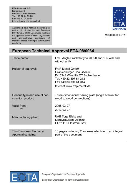
<strong>European</strong> <strong>Technical</strong> <strong>Approval</strong> <strong>ETA</strong>-<strong>08</strong>/<strong>0064</strong><br />
Trade name:<br />
Holder of approval:<br />
Generic type and use of construction<br />
product:<br />
Valid from:<br />
to:<br />
Manufacturing plant:<br />
This <strong>European</strong> <strong>Technical</strong><br />
<strong>Approval</strong> contains:<br />
MEMBER OF EOTA<br />
FraP Angle Brackets type 70, 90 and 105 with and<br />
without a rib<br />
FraP Metall GmbH<br />
Oranienburger Chaussee 6<br />
D-16348 Wandlitz OT Stolzenhagen<br />
Tel. +49 33 397 64 313<br />
Fax +49 33 397 64 314<br />
Internet www.frap-metall.de<br />
Three-dimensional nailing plate (angle bracket for<br />
wood to wood connections)<br />
20<strong>08</strong>-03-27<br />
2013-03-27<br />
UAB Toga Elektrenai<br />
Kietaviskusen; Obeniuk<br />
LT-21413 Elektrenu sav<br />
18 pages including 2 annexes which form an integral<br />
part of the document
I LEGAL BASIS AND GENERAL<br />
CONDITIONS<br />
Page 2 of 18 of <strong>European</strong> <strong>Technical</strong> <strong>Approval</strong> no. <strong>ETA</strong>-<strong>08</strong>/<strong>0064</strong><br />
1 This <strong>European</strong> <strong>Technical</strong> <strong>Approval</strong> is issued by<br />
<strong>ETA</strong>-<strong>Danmark</strong> A/S in accordance with:<br />
- Council Directive 89/106/EEC of 21 December<br />
1988 on the approximation of laws, regulations<br />
and administrative provisions of Member States<br />
relating to construction products 1) , as amended by<br />
Council Directive 93/68/EEC of 22 July 1993 2) .<br />
- Bekendtgørelse 559 af 27-06-1994 (afløser<br />
bekendtgørelse 480 af 25-06-1991) om ikrafttræden<br />
af EF direktiv af 21. december 1988 om<br />
indbyrdes tilnærmelse af medlemsstaternes love<br />
og administrative bestemmelser om byggevarer.<br />
- Common Procedural Rules for Requesting,<br />
Preparing and the Granting of <strong>European</strong> <strong>Technical</strong><br />
<strong>Approval</strong>s set out in the Annex to Commission<br />
Decision 94/23/EC 3) .<br />
- EOTA Guideline <strong>ETA</strong>G 015 Three-dimensional<br />
nailing plates, September 2002 edition.<br />
2 <strong>ETA</strong>-<strong>Danmark</strong> A/S is authorized to check whether<br />
the provisions of this <strong>European</strong> <strong>Technical</strong><br />
<strong>Approval</strong> are met. Checking may take place in<br />
the manufacturing plant. Nevertheless, the<br />
responsibility for the conformity of the products<br />
to the <strong>European</strong> <strong>Technical</strong> <strong>Approval</strong> and for their<br />
fitness for the intended use remains with the<br />
holder of the <strong>European</strong> <strong>Technical</strong> <strong>Approval</strong>.<br />
3 This <strong>European</strong> <strong>Technical</strong> <strong>Approval</strong> is not to be<br />
transferred to manufacturers or agents of manufacturers<br />
other than those indicated on page 1, or<br />
manufacturing plants other than those indicated<br />
on page 1 of this <strong>European</strong> <strong>Technical</strong> <strong>Approval</strong>.<br />
4 This <strong>European</strong> <strong>Technical</strong> <strong>Approval</strong> may be<br />
withdrawn by <strong>ETA</strong>-<strong>Danmark</strong> A/S pursuant to<br />
Article 5(1) of Council Directive89/106/EEC.<br />
1) Official Journal of the <strong>European</strong> Communities N o L40, 11 Feb 1989, p 12.<br />
2) Official Journal of the <strong>European</strong> Communities N o L220, 30 Aug 1993, p 1.<br />
3) Official Journal of the <strong>European</strong> Communities N o L 17, 20 Jan 1994, p 34.<br />
5 Reproduction of this <strong>European</strong> <strong>Technical</strong> <strong>Approval</strong><br />
including transmission by electronic means shall be<br />
in full. However, partial reproduction can be made<br />
with the written consent of <strong>ETA</strong>-<strong>Danmark</strong> A/S. In<br />
this case partial reproduction has to be designated as<br />
such. Texts and drawings of advertising brochures<br />
shall not contradict or misuse the <strong>European</strong><br />
<strong>Technical</strong> <strong>Approval</strong>.<br />
6 This <strong>European</strong> <strong>Technical</strong> <strong>Approval</strong> is issued by<br />
<strong>ETA</strong>-<strong>Danmark</strong> A/S in English.<br />
This version corresponds fully to the version circulated<br />
within EOTA. Translations into other languages<br />
have to be designated as such.
Page 3 of 18 of <strong>European</strong> <strong>Technical</strong> <strong>Approval</strong> no. <strong>ETA</strong>-<strong>08</strong>/<strong>0064</strong><br />
I SPECIAL CONDITIONS OF THE<br />
EUROPEAN TECHNICAL APPROVAL<br />
1 Definition of product and intended use<br />
Definition of the product<br />
FraP angle brackets type 70, 90 and 105 with and without a<br />
rib are one-piece non-welded, face-fixed angle brackets to<br />
be used in timber to timber connections. They are<br />
connected to the timber elements by a range of profiled<br />
nails.<br />
The angle brackets are made from pre-galvanized steel DX<br />
51 D / Z 275 according to EN 10327:2004 with a<br />
minimum yield strength Re of 295 MPa, a minimum tensile<br />
strength Rm of 360 MPa and a minimum ultimate strain A80<br />
of 22 % and are available with or without an embossed rib.<br />
Dimensions, hole positions and typical installations are<br />
shown in Annex A. FraP angle brackets are made from<br />
steel with tolerances according to EN 10143.<br />
Intended use<br />
The angle brackets are intended for use in making<br />
connections in load bearing timber structures, as a<br />
connection between a beam and a purlin, where<br />
requirements for mechanical resistance and stability and<br />
safety in use in the sense of the Essential Requirements 1<br />
and 4 of Council Directive 89/106/EEC shall be fulfilled.<br />
The connection may be with a single angle bracket or with<br />
an angle bracket on each side of the fastened timber member<br />
(see Annex A).<br />
The static and kinematic behaviour of the timber members<br />
or the supports shall be as described in Annex B.<br />
The wood members can be of solid timber, glued laminated<br />
timber and similar glued members, or wood-based structural<br />
members with a characteristic density from 290 kg/m 3 to<br />
420 kg/m 3 . This requirement to the material of the wood<br />
members can be fulfilled by using the following materials:<br />
• Structural solid timber classified to C14-C40<br />
according to EN 338 / EN 14<strong>08</strong>1,<br />
• Glulam classified to GL24-GL36 according to<br />
EN 1194 / EN 14<strong>08</strong>0,<br />
• LVL according to EN 14374,<br />
• Parallam PSL,<br />
• Intrallam LSL,<br />
• Duo- and Triobalken,<br />
• Layered wood plates,<br />
• Plywood according to EN 636<br />
Annex B states the load-carrying capacities of the angle<br />
bracket connections for a characteristic density of 350<br />
kg/m 3 . For timber or wood based material with a lower<br />
characteristic density than 350 kg/m 3 the load-carrying<br />
capacities shall be reduced by the kdens factor:<br />
kdens<br />
ρk<br />
=<br />
350<br />
⎛ ⎞<br />
⎜ ⎟<br />
⎝ ⎠<br />
2<br />
Where ρk ist he characteristic density of the timber in<br />
kg/m 3 .<br />
The design of the connections shall be in accordance with<br />
Eurocode 5 or a similar national Timber Code. The wood<br />
members shall have a thickness which is larger than the<br />
penetration depth of the nails into the members.<br />
The angle brackets are primarily for use in timber structures<br />
subject to the dry, internal conditions defined by service<br />
class 1 and 2 of Eurocode 5 and for connections subject to<br />
static or quasi-static loading.<br />
The angle brackets may also be used for connections<br />
between a timber member and a member of concrete or<br />
steel.<br />
Assumed working life<br />
The assumed intended working life of the angle brackets<br />
for the intended use is 50 years, provided that they are<br />
subject to appropriate use and maintenance.<br />
The information on the working life should not be regarded<br />
as a guarantee provided by the manufacturer or<br />
<strong>ETA</strong> <strong>Danmark</strong>. An “assumed intended working life”<br />
means that it is expected that, when this working life has<br />
elapsed, the real working life may be, in normal use<br />
conditions, considerably longer without major degradation<br />
affecting the essential requirements.
Page 4 of 18 of <strong>European</strong> <strong>Technical</strong> <strong>Approval</strong> no. <strong>ETA</strong>-<strong>08</strong>/<strong>0064</strong><br />
2 Characteristics of product and assessment<br />
<strong>ETA</strong>G<br />
paragraph<br />
6.1.1<br />
6.1.2<br />
6.1.3<br />
6.2.1<br />
6.3.1<br />
6.7.1<br />
6.7.2<br />
6.7.3<br />
Characteristic<br />
2.1 Mechanical resistance and stability*)<br />
Characteristic load-carrying capacity<br />
Stiffness<br />
Ductility in cyclic testing<br />
2.2 Safety in case of fire<br />
Reaction to fire<br />
2.3 Hygiene, health and the environment<br />
Influence on air quality<br />
2.4 Safety in use<br />
2.5 Protection against noise<br />
2.6 Energy economy and heat retention<br />
2.7 Related aspects of serviceability<br />
Durability<br />
Serviceability<br />
Identification<br />
Assessment of characteristic<br />
See Annex B<br />
No performance determined<br />
No performance determined<br />
The angle brackets are made from steel<br />
classified as Euroclass A1 in accordance with<br />
EN 1350-1 and EC decision 96/603/EC,<br />
amended by EC Decision 2000/605/EC<br />
No dangerous materials **)<br />
Not relevant<br />
Not relevant<br />
Not relevant<br />
The angle brackets have been assessed as<br />
having satisfactory durability and serviceability<br />
when used in timber structures using the timber<br />
species described in Eurocode 5 and subject to<br />
the conditions defined by service class 1 and 2<br />
See Annex A<br />
*) See page 5 of this <strong>ETA</strong><br />
**) In accordance with http://europa.eu.int-/comm/enterprise/construction/internal/dangsub/dangmain.htm In addition to the specific clauses relating to dangerous<br />
substances contained in this <strong>European</strong> <strong>Technical</strong> <strong>Approval</strong>, there may be other requirements applicable to the products falling within its scope (e.g. transposed <strong>European</strong><br />
legislation and national laws, regulations and administrative provisions). In order to meet the provisions of the EU Construction Products Directive, these requirements<br />
need also to be complied with, when and where they apply.
Safety principles and partial factors<br />
Page 5 of 18 of <strong>European</strong> <strong>Technical</strong> <strong>Approval</strong> no. <strong>ETA</strong>-<strong>08</strong>/<strong>0064</strong><br />
The characteristic load-carrying capacities are based on the<br />
characteristic values of the nail connections and the steel<br />
plates. To obtain design values the capacities have to be<br />
multiplied with different partial factors for the material<br />
properties, in addition the nail connection with the<br />
coefficient kmod.<br />
According to EN 1990 (Eurocode – Basis of design)<br />
paragraph 6.3.5 the design value of load-carrying capacity<br />
can be determined by reducing the characteristic values of<br />
the load-carrying capacity with different partial factors.<br />
Thus, the characteristic values of the load–carrying<br />
capacity are determined also for timber failure FRk,H<br />
(obtaining the embedment strength of nails subjected to<br />
shear or the withdrawal capacity of the most loaded nail,<br />
respectively) as well as for steel plate failure FRk,S. The<br />
design value of the load–carrying capacity is the smaller<br />
value of both load–carrying capacities.<br />
⎧⎪kmod ⋅FRk,HFRk,S⎫⎪<br />
FRd = min ⎨ ; ⎬<br />
⎪⎩ γM,H γM,S<br />
⎪⎭<br />
Therefore, for timber failure the load duration class and the<br />
service class are included. The different partial factors γM<br />
for steel or timber, respectively, are also correctly taken<br />
into account.<br />
2.1 Mechanical resistance and stability<br />
See annex B for the characteristic load-carrying capacity<br />
in the different directions F1 to F5.<br />
The characteristic capacities of the angle brackets are<br />
determined by calculation assisted by testing as described<br />
in the EOTA Guideline 015 clause 5.1.2. They should be<br />
used for designs in accordance with Eurocode 5 or a<br />
similar national Timber Code.<br />
Threaded nails (ringed shank nails) in accordance to<br />
prEN 14592<br />
In the formulas in Annex B the capacities for threaded<br />
nails calculated from the formulas of Eurocode 5 are<br />
used assuming a thick steel plate when calculating the<br />
lateral nail load-carrying-capacity.<br />
The load bearing capacities of the brackets has been<br />
determined based on the use of connector nails 4,0 x 40<br />
mm in accordance with the German national approval for<br />
the nails.<br />
The characteristic withdrawal capacity of the nails has to<br />
be determined by calculation in accordance with EN 1995-<br />
1-1: 2004, paragraph 8.3.2 (head pull-through is not<br />
relevant):<br />
Fax,Rk = fax,k × d × tpen<br />
Where:<br />
fax,k Characteristic value of the withdrawal parameter<br />
in N/mm 2<br />
d Nail diameter in mm<br />
Penetration depth of the profiles shank in mm<br />
tpen<br />
Based on tests by Versuchsanstalt für Stahl, Holz und<br />
Steine, University of Kalrsruhe, the characteristic value of<br />
the withdrawal resistance for the threaded nails used can<br />
be calculated as:<br />
fax,k = 50 × 10 -6 × σk 2<br />
Where:<br />
σk<br />
Characteristic density of the timber in kg/m 3<br />
The shape of the nail directly under the head shall be in the<br />
form of a truncated cone with a diameter under the nail<br />
head which exceeds the hole diameter.<br />
The design models allow the use of fasteners described in<br />
the table on page 9 in Annex A<br />
No performance has been determined in relation to<br />
ductility of a joint under cyclic testing. The contribution to<br />
the performance of structures in seismic zones, therefore,<br />
has not been assessed.<br />
No performance has been determined in relation to the<br />
joint’s stiffness properties - to be used for the analysis of<br />
the serviceability limit state.<br />
2.7 Related aspects of serviceability<br />
2.7.1 Corrosion protection in service class 1 and 2.<br />
In accordance with <strong>ETA</strong>G 015 the angle brackets are made<br />
from pre-galvanized steel DX 51 D / Z 275 according to<br />
EN 10327:2004 with minimum yield strength Re of 295<br />
MPa, a minimum tensile strength Rm of 360 MPa and a<br />
minimum ultimate strain A80 of 22 %
3 Attestation of Conformity and<br />
CE marking<br />
3.1 Attestation of Conformity system<br />
Page 6 of 18 of <strong>European</strong> <strong>Technical</strong> <strong>Approval</strong> no. <strong>ETA</strong>-<strong>08</strong>/<strong>0064</strong><br />
The system of attestation of conformity is 2+<br />
described in Council Directive 89/106/EEC<br />
(Construction Products Directive) Annex III.<br />
a) Tasks for the manufacturer:<br />
(1) Factory production control,<br />
(2) Initial type testing of the product,<br />
b) Tasks for the notified body:<br />
3.2 Responsibilities<br />
(1) Initial inspection of the factory and the<br />
factory production control,<br />
(2) Continuous surveillance<br />
3.2.1 Tasks of the manufacturer<br />
3.2.1.1 Factory production control<br />
The manufacturer has a factory production control<br />
system in the plant and exercises permanent internal<br />
control of production. All the elements, requirements<br />
and provisions adopted by the manufacturer are<br />
documented in a systematic manner in the form of<br />
written policies and procedures. This production<br />
control system ensures that the product is in<br />
conformity with the <strong>European</strong> <strong>Technical</strong> <strong>Approval</strong>.<br />
The manufacturer shall only use raw materials<br />
supplied with the relevant inspection documents as<br />
laid down in the control plan 4 . The incoming raw<br />
materials shall be subject to controls and tests by the<br />
manufacturer before acceptance. Check of materials,<br />
such as sheet metal, shall include control of the<br />
inspection documents presented by suppliers<br />
(comparison with nominal values) by verifying<br />
dimension and determining material properties, e.g.<br />
chemical composition, mechanical properties and<br />
zinc coating thickness.<br />
The manufactured components are checked visually<br />
and for dimensions.<br />
The control plan, which is part of the technical<br />
documentation of this <strong>European</strong> <strong>Technical</strong> <strong>Approval</strong>,<br />
4 The control plan has been deposited at <strong>ETA</strong>-<strong>Danmark</strong> and is<br />
only made available to the approved bodies involved in the<br />
conformity attestation procedure.<br />
includes details of the extent, nature and frequency<br />
of testing and controls to be performed within the<br />
factory production control and has been agreed<br />
between the approval holder and <strong>ETA</strong> <strong>Danmark</strong>.<br />
The results of factory production control are<br />
recorded and evaluated. The records include at least<br />
the following information:<br />
- Designation of the product, basic material and<br />
components;<br />
- Type of control or testing;<br />
- Date of manufacture of the product and date of<br />
testing of the product or basic material and<br />
components;<br />
- Result of control and testing and, if appropriate,<br />
comparison with requirements;<br />
- Signature of person responsible for factory<br />
production control.<br />
The records shall be presented to <strong>ETA</strong> <strong>Danmark</strong> on<br />
request.<br />
3.2.1.1 Initial type testing of the product<br />
For initial type-testing the results of the tests<br />
performed as part of the assessment for the <strong>European</strong><br />
<strong>Technical</strong> <strong>Approval</strong> shall be used unless there are<br />
changes in the production line or plant. In such cases<br />
the necessary initial type testing has to be agreed<br />
between <strong>ETA</strong> <strong>Danmark</strong> and the notified body.<br />
3.2.2. Tasks of notified bodies<br />
3.2.2.1 Initial inspection of the factory and the factory<br />
production control<br />
The approved body should ascertain that, in<br />
accordance with the control plan, the factory, in<br />
particular the staff and equipment, and the factory<br />
production control, are suitable to ensure a<br />
continuous and orderly manufacturing of the angle<br />
brackets with the specifications given in part 2.<br />
3.2.2.2 Continuous surveillance<br />
The approved body shall visit the factory at least<br />
twice a year for routine inspections. It shall be<br />
verified that the system of factory production control<br />
and the specified manufacturing processes are<br />
maintained, taking account of the control plan.<br />
The results of product certification and continuous<br />
surveillance shall be made available on demand by<br />
the certification body to <strong>ETA</strong> <strong>Danmark</strong>. Where the<br />
provisions of the <strong>European</strong> <strong>Technical</strong> <strong>Approval</strong> and<br />
the control plan are no longer fulfilled, the certificate
Page 7 of 18 of <strong>European</strong> <strong>Technical</strong> <strong>Approval</strong> no. <strong>ETA</strong>-<strong>08</strong>/<strong>0064</strong><br />
of conformity shall be withdrawn by the approved<br />
body.<br />
3.3 CE marking<br />
The CE marking shall be affixed on each packaging<br />
of angle brackets. The initials "CE" shall be<br />
followed by the identification number of the notified<br />
body and shall be accompanied by the following<br />
information:<br />
- Name or identifying mark of the<br />
manufacturer<br />
- The last two digits of the year in which the<br />
marking was affixed<br />
- Number of the <strong>European</strong> <strong>Technical</strong><br />
<strong>Approval</strong><br />
- Name and size of product<br />
- Number of the <strong>ETA</strong> Guideline<br />
(<strong>ETA</strong>G no. 015)<br />
- Number of the EC Certificate of<br />
Conformity
Page 8 of 18 of <strong>European</strong> <strong>Technical</strong> <strong>Approval</strong> no. <strong>ETA</strong>-<strong>08</strong>/<strong>0064</strong><br />
4 Assumptions under which the fitness of the<br />
product for the intended use was favourably<br />
assessed<br />
4.1 Manufacturing<br />
FraP angle brackets are manufactured in accordance with<br />
the provisions of this <strong>European</strong> <strong>Technical</strong> <strong>Approval</strong> using<br />
the manufacturing processes as identified in the inspection<br />
of the plant by the notified inspection body and laid down<br />
in the technical documentation.<br />
4.2 Installation<br />
The nailing pattern used shall be either the maximum or<br />
the minimum pattern as defined in Annex A.<br />
Wane under the flaps of the angle bracket is allowed<br />
provided it does not occur under the nails. Wane can<br />
reduce the load-bearing capacity of the connection.<br />
Thomas Bruun<br />
Manager, <strong>ETA</strong>-<strong>Danmark</strong><br />
A gap between the connector and the timber member is<br />
not allowed. However, where the angle bracket is used for<br />
a connection between a beam and a column a gap of 5 mm<br />
is allowed.<br />
The execution of the connection shall be in accordance<br />
with the approval holder’s technical literature.<br />
4.3 Maintenance and repair<br />
Maintenance is not required during the assumed intended<br />
working life. Should repair prove necessary, it is normal to<br />
replace the angle bracket.
Page 9 of 18 of <strong>European</strong> <strong>Technical</strong> <strong>Approval</strong> no. <strong>ETA</strong>-<strong>08</strong>/<strong>0064</strong><br />
Bracket type Thickness<br />
(mm)<br />
Annex A<br />
Product details and definitions<br />
Table A.1 Materials specification<br />
Steel specification Coating specification<br />
70 without rib 2,5 DX 51 D / Z 275 Z 275<br />
90 without rib 2,5 DX 51 D / Z 275 Z 275<br />
105 without rib 3,0 DX 51 D / Z 275 Z 275<br />
70 with rib 2,5 DX 51 D / Z 275 Z 275<br />
90 with rib 2,5 DX 51 D / Z 275 Z 275<br />
105 with rib 3,0 DX 51 D / Z 275 Z 275<br />
Table A.2 Range of sizes<br />
Bracket type Height (mm) Width (mm)<br />
min max min max<br />
70 without rib 70 70 55 55<br />
90 without rib 90 90 65 65<br />
105 without rib 105 105 90 90<br />
70 with rib 70 70 53 55<br />
90 with rib 90 90 61 65<br />
105 with rib 105 105 84 90<br />
Table A.3 Fastener specification<br />
Nail type Nail size (mm) Finish<br />
According to prEN 14592 Diameter Length<br />
Threaded nail with a profiled length of at least 30 mm 4,0 40 Electroplated zinc
Page 10 of 18 of <strong>European</strong> <strong>Technical</strong> <strong>Approval</strong> no. <strong>ETA</strong>-<strong>08</strong>/<strong>0064</strong><br />
Figure A.1 Dimensions of Figure A.2 Dimensions of<br />
Angle Bracket 70 without rib Angle Bracket 90 without rib<br />
Figure A.3 Dimensions of Figure A.4 Dimensions of<br />
Angle Bracket 105 without rib Angle Bracket 70 with rib
Page 11 of 18 of <strong>European</strong> <strong>Technical</strong> <strong>Approval</strong> no. <strong>ETA</strong>-<strong>08</strong>/<strong>0064</strong><br />
Figure A.5 Dimensions of Figure A.6 Dimensions of<br />
Angle Bracket 90 with rib Angle Bracket 105 with rib<br />
Figure A.7 Typical installation
Page 12 of 18 of <strong>European</strong> <strong>Technical</strong> <strong>Approval</strong> no. <strong>ETA</strong>-<strong>08</strong>/<strong>0064</strong><br />
Nail Patterns – Angle Bracket 70 without rib<br />
LC 1 – column LC 1 – purlin, LC 2,3, LC 4,5<br />
Nails in hole number: Nails in hole number:<br />
1,2,3 / 1,3,4,6,7 /<br />
12,13,14,20,21,22 12,13,14,20,21,22<br />
Nail Patterns – Angle Bracket 90 without rib<br />
LC 1 – column LC 1 – purlin, LC 2,3, LC 4,5<br />
Nails in hole number: Nails in hole number:<br />
1,2 / 1,2,4,8,9,10,11 /<br />
14,15,19,20,24,25 14,15,19,20,24,25<br />
Nail Patterns – Angle Bracket 105 without rib<br />
LC 1 – column LC 1 – purlin, LC 2,3, LC 4,5<br />
Nails in hole number: Nails in hole number:<br />
1,2,6,7,8,9,10 / 1,2,6,8,10,14,15 /<br />
18,19,20,21,22,23 18,19,20,21,22,23,<br />
27,28,30,35,36 27,28,30,35,36
Page 13 of 18 of <strong>European</strong> <strong>Technical</strong> <strong>Approval</strong> no. <strong>ETA</strong>-<strong>08</strong>/<strong>0064</strong><br />
Nail Patterns – Angle Bracket 70 with rib<br />
LC 1 – column LC 1 – purlin, LC 2,3, LC 4,5<br />
Nails in hole number: Nails in hole number:<br />
1,2,3 / 1,3,4,6 /<br />
9,10,14,15,16 9,10,14,15,16<br />
Nail Patterns – Angle Bracket 90 with rib<br />
LC 1 – column LC 1 – purlin, LC 2,3, LC 4,5<br />
Nails in hole number: Nails in hole number:<br />
1,2 / 1,2,4,8,9 /<br />
14,15,18,19,25,26 14,15,18,19,25,26<br />
Nail Patterns – Angle Bracket 105 with rib<br />
LC 1 – column LC 1 – purlin, LC 2,3, LC 4,5<br />
Nails in hole number: Nails in hole number:<br />
1,2,6,7 / 1,2,6,7,8,9,10,11 /<br />
14,15,16,17,20,21,27,28 14,15,16,17,20,21,27,28
Page 14 of 18 of <strong>European</strong> <strong>Technical</strong> <strong>Approval</strong> no. <strong>ETA</strong>-<strong>08</strong>/<strong>0064</strong><br />
Annex B<br />
Characteristic load-carrying capacities<br />
Table 1: Force F1 Column, 2 angle brackets / connection<br />
Type Nail number n V Nail number n h<br />
R k,1 [kN] (column)<br />
Timber Steel<br />
70 without rib 1,2,3 12,13,14,20,21,22 3,1 1,8<br />
90 without rib 1,2 14,15,19,20,24,25 2,4 3,5<br />
105 without rib 1,2,6,7,8,9,10 18,19,20,21,22,23,27,28,30,35,36 7,1 4,0<br />
70 with rib 1,2,3 9,10,14,15,16 2,0 2,1<br />
90 with rib 1,2 14,15,18,19,25,26 2,4 9,1<br />
105 with Rib 1,2,6,7 14,15,16,17,20,21,27,28 4,9 14,8<br />
Table 2: Force F1 Column, 1 angle bracket / connection<br />
Type Nail number n V Nail number n h<br />
R k,1 [kN] (column)<br />
Timber Steel<br />
70 without rib 1,2,3 12,13,14,20,21,22 1,5 0,9<br />
90 without rib 1,2 14,15,19,20,24,25 1,2 1,7<br />
105 without rib 1,2,6,7,8,9,10 18,19,20,21,22,23,27,28,30,35,36 3,5 2,0<br />
70 with rib 1,2,3 9,10,14,15,16 1,0 1,0<br />
90 with rib 1,2 14,15,18,19,25,26 1,2 4,5<br />
105 with rib 1,2,6,7 14,15,16,17,20,21,27,28 2,4 7,4<br />
Table 3: Force F1 Purlin, 2 angle brackets / connection<br />
Type Nail number n V Nail number n h<br />
R k,1 [kN] (column)<br />
Timber Steel<br />
70 without rib 1,3,4,6,7 12,13,14,20,21,22 3,1 1,8<br />
90 without rib 1,2,4,8,9,10,11 14,15,19,20,24,25 2,4 3,5<br />
105 without rib 1,2,6,8,10,14,15 18,19,20,21,22,23,27,28,30,35,36 7,1 4,0<br />
70 with Rib 1,3,4,6 9,10,14,15,16 2,0 2,1<br />
90 with rib 1,2,4,8,9 14,15,18,19,25,26 2,4 9,1<br />
105 with rib 1,2,6,7,8,9,10,11 14,15,16,17,20,21,27,28 4,9 14,8
Page 15 of 18 of <strong>European</strong> <strong>Technical</strong> <strong>Approval</strong> no. <strong>ETA</strong>-<strong>08</strong>/<strong>0064</strong><br />
Table 4: Force F1 Purlin, 1 angle bracket / connection<br />
Type Nail number n V Nail number n h<br />
R k,1 [kN] (column)<br />
Timber Steel<br />
70 without rib 1,3,4,6,7 12,13,14,20,21,22 1,5 0,9<br />
90 without rib 1,2,4,8,9,10,11 14,15,19,20,24,25 1,2 1,7<br />
105 without rib 1,2,6,8,10,14,15 18,19,20,21,22,23,27,28,30,35,36 3,5 2,0<br />
70 with rib 1,3,4,6 9,10,14,15,16 1,0 1,0<br />
90 with rib 1,2,4,8,9 14,15,18,19,25,26 1,2 4,5<br />
105 with rib 1,2,6,7,8,9,10,11 14,15,16,17,20,21,27,28 2,4 7,4<br />
Table 5: Forces F2,3, 2 angle brackets / connection<br />
Type Nail number n V Nail number n h e 1 [mm] R k,h,2,3/ R k,v,2,3<br />
R k,2,3 [kN]<br />
70 without rib 1,3,4,6,7 12,13,14,20,21,22 34,9 1 5,8<br />
90 without rib 1,2,4,8,9,10,11 14,15,19,20,24,25 49,3 1 7,2<br />
105 without rib 1,2,6,8,10,14,15 18,19,20,21,22,23,27,28,30,35,36 41,7 1 8,7<br />
70 with rib 1,3,4,6 9,10,14,15,16 42,2 1 5,2<br />
90 with rib 1,2,4,8,9 14,15,18,19,25,26 44,3 1 5,4<br />
105 with rib 1,2,6,7,8,9,10,11 14,15,16,17,20,21,27,28 45,4 1 9,0<br />
Table 6: Forces F2,3, 1 angle bracket / connection<br />
Type Nail number n V Nail number n h e 1 [mm] R k,h,2,3/ R k,v,2,3<br />
Timber<br />
R k,2,3 [kN]<br />
70 without rib 1,3,4,6,7 12,13,14,20,21,22 34,9 1 2,9<br />
90 without rib 1,2,4,8,9,10,11 14,15,19,20,24,25 49,3 1 3,6<br />
105 without rib 1,2,6,8,10,14,15 18,19,20,21,22,23,27,2830,35,36 41,7 1 4,3<br />
70 with rib 1,3,4,6 9,10,14,15,16 42,2 1 2,6<br />
90 with rib 1,2,4,8,9 14,15,18,19,25,26 44,3 1 2,7<br />
105 with rib 1,2,6,7,8,9,10,11 14,15,16,17,20,21,27,28 45,4 1 4,5<br />
Timber
Page 16 of 18 of <strong>European</strong> <strong>Technical</strong> <strong>Approval</strong> no. <strong>ETA</strong>-<strong>08</strong>/<strong>0064</strong><br />
Table 7: Basic Forces F4,5, 2 angle brackets / connection<br />
Type Nail number n V Nail number n h<br />
R k,4,5 [kN]<br />
Timber Steel<br />
70 without rib 1,3,4,6,7 12,13,14,20,21,22 4,8 4,3<br />
90 without rib 1,2,4,8,9,10,11 14,15,19,20,24,25 6,1 4,4<br />
105 without rib 1,2,6,8,10,14,15 18,19,20,21,22,23,27,28,30,35,36 6,9 8,9<br />
70 with rib 1,3,4,6 9,10,14,15,16 6,6 5,3<br />
90 with rib 1,2,4,8,9 14,15,18,19,25,26 7,0 6,7<br />
105 with rib 1,2,6,7,8,9,10,11 14,15,16,17,20,21,27,28 8,6 12,5<br />
Table 8: Basic Forces F4, 1 angle bracket / connection<br />
Type Nail number n V Nail number n h<br />
R k,4,5 [kN]<br />
Timber Steel<br />
70 with rib 1,3,4,6 9,10,14,15,16 8,0 4,2<br />
90 with rib 1,2,4,8,9 14,15,18,19,25,26 9,2 5,2<br />
105 with rib 1,2,6,7,8,9,10,11 14,15,16,17,20,21,27,28 12,5 8,7<br />
Table 9: Basic Forces F5, 1 angle bracket / connection<br />
Type Nail number n V Nail number n h<br />
R k,4,5 [kN]<br />
Timber Steel<br />
70 with rib 1,3,4,6 9,10,14,15,16 1,3 1,1<br />
90 with rib 1,2,4,8,9 14,15,18,19,25,26 1,6 1,5<br />
105 with rib 1,2,6,7,8,9,10,11 14,15,16,17,20,21,27,28 2,6 4,1
Page 17 of 18 of <strong>European</strong> <strong>Technical</strong> <strong>Approval</strong> no. <strong>ETA</strong>-<strong>08</strong>/<strong>0064</strong><br />
Definitions of forces, their directions and eccentricity<br />
Forces - Beam to beam connection<br />
Fastener specification<br />
Holes are marked with numbers referring to the nailing pattern in Annex A.<br />
Double angle brackets per connection<br />
The angle brackets must be placed at each side opposite each other, symmetric to the component axis.<br />
Acting forces<br />
F1<br />
F2 and F3<br />
F4 and F5<br />
Lifting force acting along the central axis of the joint.<br />
Lateral force acting in the joint between the component 2 and component 1 in the<br />
component 2 direction<br />
Lateral force acting in the component 1 direction along the central axis of the joint. If<br />
the load is applied with an eccentricity e, a design for combined loading is required.<br />
Single angle bracket per connection<br />
Acting forces<br />
F1<br />
Lifting force acting in the central axis of the angle bracket. The component 2 shall be<br />
prevented from rotation. If the component 2 is prevented from rotation the loadcarrying<br />
capacity will be half of a connection with double angle brackets.<br />
F2 and F3 Lateral force acting in the joint between the component 2 and the component 1 in the<br />
component 2 direction. The component 2 shall be prevented from rotation. If the<br />
component 2 is prevented from rotation the load-carrying capacity will be half of a<br />
connection with double angle brackets.<br />
F4 and F5 Lateral force acting in the component 1 direction in the height of the top edge of<br />
component 2. F4 is the lateral force towards the angle bracket; F5 is the lateral force<br />
away from the angle bracket. Only the characteristic load-carrying capacities for angle<br />
brackets with ribs are given.<br />
Wane<br />
Wane is not allowed, the timber has to be sharp-edged in the area of the angle brackets.<br />
Timber splitting<br />
For the lifting force F1 it must be checked in accordance with Eurocode 5 or a similar national Timber<br />
Code that splitting will not occur.<br />
Combined forces<br />
Component 2<br />
If the forces F1 and F2/F3 or F4/F5 act at the same time, the following inequality shall be fulfilled:<br />
2 2 2 2 2<br />
⎛ F ⎞ ⎛ 1,d F ⎞ ⎛ 2,d F ⎞ ⎛ 3,d F ⎞ ⎛ 4,d F ⎞ 5,d<br />
⎜ ⎟<br />
F ⎟ ⎜ ⎟<br />
Rd,1 F ⎟ ⎜ ⎟ ⎜ ⎟ ⎜ ⎟<br />
Rd,2 F ⎟ ⎜<br />
Rd,3 F ⎟ ⎜<br />
Rd,4 F ⎟<br />
⎝ ⎠ ⎝ ⎠ ⎝ ⎠ ⎝ ⎠ ⎝ Rd,5 ⎠<br />
F2<br />
Component 1<br />
+ + + + ≤1<br />
F1<br />
F3<br />
F5<br />
b<br />
F1<br />
F4<br />
Component 1<br />
e
Page 18 of 18 of <strong>European</strong> <strong>Technical</strong> <strong>Approval</strong> no. <strong>ETA</strong>-<strong>08</strong>/<strong>0064</strong><br />
The forces F2 and F3 or F4 and F5 are forces with opposite direction. Therefore only one force F2 or F3,<br />
respectively, and F4 or F5, respectively, is able to act simultaneously with F1, while the other shall be set to<br />
zero.<br />
If the load F4/F5 is applied with an eccentricity e, a design for combined loading for connections with<br />
double angle brackets is required. Here, an additional force ∆ F1 has to be added to the existing force F1.<br />
e<br />
∆ F1,d = F 4,d /F5,d⋅<br />
B<br />
B is the width of component 2.