Power train – Heat exchangers - European Aluminium Association
Power train – Heat exchangers - European Aluminium Association
Power train – Heat exchangers - European Aluminium Association

You also want an ePaper? Increase the reach of your titles
YUMPU automatically turns print PDFs into web optimized ePapers that Google loves.
Applications <strong>–</strong> <strong>Power</strong> <strong>train</strong> <strong>–</strong> <strong>Heat</strong> <strong>exchangers</strong><br />
Table of contents<br />
7 <strong>Heat</strong> <strong>exchangers</strong>............................................................................................................................ 2<br />
7.1 General aspects....................................................................................................................... 2<br />
7.1.1 Brief history..................................................................................................................... 3<br />
7.1.2 Applications of heat <strong>exchangers</strong>......................................................................................... 3<br />
7.1.3 Advantages of aluminium in the design of heat <strong>exchangers</strong> .................................................. 3<br />
7.2 Design and manufacturing of aluminium heat <strong>exchangers</strong>........................................................... 4<br />
7.2.1 Mechanically assembled heat <strong>exchangers</strong> ........................................................................... 6<br />
7.2.2 Brazed aluminium heat <strong>exchangers</strong> .................................................................................... 7<br />
7.3 Material requirements and functions......................................................................................... 8<br />
7.3.1 Fin material...................................................................................................................... 9<br />
7.3.2 Bare and clad rolled materials for headers, plates, longitudinally welded tubes, etc. ............. 10<br />
7.4 Applications ......................................................................................................................... 14<br />
7.4.1 Engine cooling system (radiators) .................................................................................... 14<br />
7.4.2 Oil coolers ..................................................................................................................... 19<br />
7.4.3 <strong>Heat</strong>er cores ................................................................................................................... 23<br />
7.4.4 Air conditioning ............................................................................................................. 25<br />
7.4.5 Charge air coolers........................................................................................................... 34<br />
7.4.6 Diesel fuel cooling.......................................................................................................... 39<br />
7.4.7 Exhaust gas heat <strong>exchangers</strong>............................................................................................ 41<br />
7.4.8 Parking heaters............................................................................................................... 42<br />
7.4.9 Cooling modules ............................................................................................................ 43<br />
7.5 Future perspectives ............................................................................................................... 44<br />
Version 2011 © <strong>European</strong> <strong>Aluminium</strong> <strong>Association</strong> (auto@eaa.be) 1
7 <strong>Heat</strong> <strong>exchangers</strong><br />
7.1 General aspects<br />
Today’s heat <strong>exchangers</strong> must meet a variety of highly demanding requirements. In terms of<br />
performance, they have to ensure maximum heat transfer while keeping size to a minimum.<br />
Furthermore, the durability of heat <strong>exchangers</strong> must be extremely high, providing trouble-free<br />
performance throughout its service life at low manufacturing costs. <strong>Aluminium</strong>, in its various<br />
forms, offers clear possibilities to achieve these goals and is also well positioned to meet the<br />
challenges of the increasing market demands for cost effective, energy-efficient products and<br />
new customized, innovative applications. This is made possible by the large variety of<br />
aluminium-based materials and product forms that empower system designers and<br />
manufacturers with multiple options for significant design improvement and cost reduction.<br />
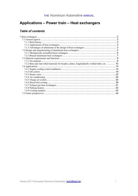
Oil cooler<br />
Source: Behr GmbH & Co. KG<br />
Version 2011 © <strong>European</strong> <strong>Aluminium</strong> <strong>Association</strong> (auto@eaa.be) 2
7.1.1 Brief history<br />
� As early as 1950, aluminium heat <strong>exchangers</strong> made moderate inroad into the<br />
automotive industry.<br />
� With the introduction of the vacuum brazing technique, large scale production of<br />
aluminium-based heat <strong>exchangers</strong> began to flourish.<br />
� Significant growth in the use of aluminium heat <strong>exchangers</strong> resulted from advantages of<br />
the controlled atmosphere brazing process (Nocolok brazing process introduced by<br />
ALCAN).<br />
� Introduction of “long life” (highly corrosion resistant) alloys further improved<br />
performance of aluminium heat <strong>exchangers</strong>.<br />
� Additional demands for aluminium heat <strong>exchangers</strong> resulted primarily from the growth<br />
of automobile air-conditioning systems and new applications due to the increasing<br />
engine performance.<br />
7.1.2 Applications of heat <strong>exchangers</strong><br />
<strong>Aluminium</strong> heat <strong>exchangers</strong> are used in one of the following main application categories:<br />
� Engine cooling (radiators)<br />
� Oil cooling (oil of the engine main lubrication circuit, the manual and automatic<br />
transmission, the power steering, etc.)<br />
� Condensers and evaporators for air-conditioning systems<br />
� <strong>Heat</strong>ers<br />
� Charge air, exhaust gas and fuel cooling.<br />
In each application, the heat exchanger must fulfil specific performance requirements asking for<br />
different design and manufacturing concepts as well as material characteristics. On the other<br />
hand, due to intensifying demands on compactness combined with light weight, heat<br />
<strong>exchangers</strong> are increasingly being produced as modules. The combination of up to four heat<br />
<strong>exchangers</strong> in a vehicle’s front structure is currently state-of-the-art, significantly reducing the<br />
overall volume, weight and cost of the total cooling system.<br />
7.1.3 Advantages of aluminium in the design of heat <strong>exchangers</strong><br />
The business case for aluminium heat <strong>exchangers</strong> is based on two components, the cost<br />
savings realized by substituting an expensive raw material, copper, with a less expensive raw<br />
material, aluminium, and, the cost savings that are made possible by implementing higher<br />
performance products and more efficient fabrication processes. <strong>Aluminium</strong> offers a number of<br />
advantageous material characteristics for heat <strong>exchangers</strong>:<br />
� Significant potential for lightweight design<br />
� Highly automated, reliable manufacturing process (brazing)<br />
� High thermal conductivity, also when joined by brazing<br />
� Excellent corrosion resistance<br />
� Good formability<br />
� Adequate strength to resist temperature and pressure cycles<br />
� Easy recyclability, i.e. an environmentally friendly solution<br />
� Commercial availability of a wide range of aluminium alloys and product forms to meet<br />
different design options.<br />
Version 2011 © <strong>European</strong> <strong>Aluminium</strong> <strong>Association</strong> (auto@eaa.be) 3
7.2 Design and manufacturing of aluminium heat <strong>exchangers</strong><br />
Although a wide variety of design concepts for aluminium heat <strong>exchangers</strong> exist, they invariably<br />
fall into one of the following categories:<br />
� Tube / fin<br />
� Plate-fin<br />
� Plate-bar<br />
� Extrusion / fin.<br />
The majority of the heat <strong>exchangers</strong> used in today’s automobiles are based on tube / fin<br />
designs. In special applications, however, conceptual designs based on other aluminium<br />
product forms may well show clear advantages.<br />
Charge air cooler in a tube / fin design<br />
Source: Behr GmbH & Co. KG<br />
There are three types of tubes for heat exchanger applications:<br />
� Welded tubes<br />
� Folded tubes<br />
� Extruded tubes, and these can be round tubes (RT) or multiport extrusions (MPE).<br />
Round extruded tubes can be subjected to a drawing operation for further reduction of the wall<br />
thickness and a closer control of the geometrical tolerances. MPE tubes are flat tubes with<br />
multiple small channels running the length of the tube, i.e. they could be described as one large<br />
tube split into multiple smaller parallel ports. The flat geometry of MPE tubes results in reduced<br />
aerodynamic drag and an advantageous development of the heat transfer boundary layer<br />
leading to larger heat transfer coefficients on the air-side. The enhanced heat transfer of MPE<br />
tubes results from the increased ratio of the heat transfer area to the internal volume, and a<br />
favourable impact on the coolant flow regime and the dominant heat transfer mechanism.<br />
Two distinct assembly techniques are used for the manufacturing of tube / fin aluminium heat<br />
<strong>exchangers</strong>:<br />
� Mechanical assembly and<br />
� Brazing.<br />
The fabrication of these two types of heat <strong>exchangers</strong> requires different processes, equipment<br />
and often different alloys. The primary advantage of mechanically assembled heat <strong>exchangers</strong><br />
compared to brazed heat <strong>exchangers</strong> is the lower investment cost. But brazed heat <strong>exchangers</strong><br />
Version 2011 © <strong>European</strong> <strong>Aluminium</strong> <strong>Association</strong> (auto@eaa.be) 4
have a better thermal performance rating in comparison to mechanically assembled ones.<br />
Consequently, brazing is today the dominating assembly method for aluminium heat<br />
<strong>exchangers</strong>. In specific cases, also other joining technologies can be applied in the production<br />
of heat exchanger components, e.g. adhesive bonding or mechanical joining methods such as<br />
clinching, self-piercing riveting, etc.<br />
The preferred design and manufacturing approach for aluminium evaporators and condensers<br />
is to combine the use of multiport extrusions with the brazing process. The considerably<br />
improved performance of these heat <strong>exchangers</strong> offers the potential for a substantial reduction<br />
in system cost through reduction of weight and size, reduced fan power requirements,<br />
increased durability, etc. <strong>Heat</strong> <strong>exchangers</strong> for single-phase liquid coolants or oils are preferably<br />
designed using round tubes as the application of multiport extrusions results in a too high<br />
pressure drop.<br />
Welded round tubes can be used in mechanically assembled heat <strong>exchangers</strong> as liquid<br />
lines or as header pipes, e.g. in brazed condensers<br />
Source: Sapa<br />
Example of a tube design combining longitudinal seam welding and folding which is<br />
normally used in e.g. heaters and radiators<br />
Source: Sapa<br />
Version 2011 © <strong>European</strong> <strong>Aluminium</strong> <strong>Association</strong> (auto@eaa.be) 5
7.2.1 Mechanically assembled heat <strong>exchangers</strong><br />
A mechanically assembled heat exchanger of the round tube plate fin (RTPF) design typically<br />
consists of extruded and sometimes drawn aluminium alloy tubes and fins stamped from rolled<br />
aluminium material. The inner surface of the tubes may be smooth or may have an enhanced<br />
surface. The enhancements can have a variety of geometrical shapes. Likewise, a great deal of<br />
effort has gone into improving air-side heat transfer using plate fins in a variety of geometries<br />
and degrees of complexity, e.g. the use of interrupted surfaces to reduce the resistance in the<br />
boundary layer.<br />
The two components are assembled by inserting (“lacing”) the tubes into the formed fin collars.<br />
At this point, the tube outer diameter is slightly undersize with respect to the fin collars, making<br />
the lacing process easy. The next step is to expand the tube diameter by inserting a mandrel<br />
and rod assembly into the tube that is larger than the tube’s inner diameter. The result is a<br />
mechanical “joint” between tube and fin that provides the conduction path for heat transfer from<br />
the refrigerant to the tube wall, to the fin and finally to the air.<br />
Mechanically expanded RTPF heat <strong>exchangers</strong> have some inherent weaknesses. Although the<br />
mechanical bond between tube and fin provides good contact, there is still a significant amount<br />
of contact resistance that reduces the effective heat conductivity. This contact resistance is may<br />
be due to oxides and/or other contaminants present in the interface between the outer tube<br />
surface and the fin collar, but also any geometrical irregularity which results in a less than<br />
perfect contact during the tube expansion process. The contact resistance will generally<br />
increase during service, further deteriorating heat transfer performance over time. The primary<br />
problem is that corrosion will result in the growth of oxides and other corrosion products that act<br />
as insulators at the fin/tube interface.<br />
Mechanically assembled aluminium radiator<br />
Source: Behr GmbH & Co., KG<br />
Version 2011 © <strong>European</strong> <strong>Aluminium</strong> <strong>Association</strong> (auto@eaa.be) 6
7.2.2 Brazed aluminium heat <strong>exchangers</strong><br />
Brazed aluminium heat <strong>exchangers</strong> show a metallurgical bond between tube and fin which has<br />
a positive impact on several performance measures. Most important is the elimination of the<br />
contact resistance between tube and fin leading to significantly improved heat conduction.<br />
Different brazing processes have been used commercially to manufacture aluminium heat<br />
<strong>exchangers</strong>:<br />
� Controlled atmosphere brazing<br />
� Vacuum brazing<br />
� Salt bath brazing<br />
� Neitz process<br />
� Ni brazing.<br />
However, aluminium heat <strong>exchangers</strong> for automotive applications are today generally produced<br />
by controlled atmosphere brazing (dominating method) and vacuum brazing. Ni brazing of<br />
automotive heat <strong>exchangers</strong> is executed today only by one major company. Salt bath brazing is<br />
still used, but only for small volume production.<br />
The manufacturing of brazed heat <strong>exchangers</strong> using tube and fin components is well<br />
established within the automotive heat exchanger industry. Highly-automated assembly and<br />
brazing processes suitable for high volume production provide both high throughput and<br />
excellent quality leading to heat <strong>exchangers</strong> comprised of joints made with 100% metallurgical<br />
bonding.<br />
<strong>Aluminium</strong> producers, brazing flux producers and furnace builders actively work together to<br />
improve and further develop the brazing processes for better economy and environmental<br />
friendliness. A wide range of heat-treatable and non heat-treatable aluminium alloys are<br />
available both for tubes and fins. Suitable aluminium materials for brazing applications (coils,<br />
sheets and tubes) can be delivered in a large variety of alloy combinations, clad ratios, sheet<br />
thicknesses and widths according to customer specifications.<br />
Brazed oil cooler<br />
Source: Novelis<br />
Version 2011 © <strong>European</strong> <strong>Aluminium</strong> <strong>Association</strong> (auto@eaa.be) 7
7.3 Material requirements and functions<br />
<strong>Aluminium</strong> alloys are now well established materials for the manufacture of automotive heat<br />
<strong>exchangers</strong>. They offer properties that can be favourably utilised in various components:<br />
� High thermal conductivity<br />
� Low density<br />
� Adequate strength (also at elevated temperatures)<br />
� Good formability<br />
� Excellent corrosion resistance.<br />
Proper selection of aluminium alloys and product forms offers the possibility to develop and<br />
produce the various types of heat <strong>exchangers</strong> used in modern automobiles and to respond to<br />
the ever increasing market demands with respect to improved heat transfer performance, but<br />
also reduction of weight, size and cost.<br />
For heat <strong>exchangers</strong>, different types of rolled as well as extruded aluminium products are used:<br />
� Flat rolled materials, e.g.:<br />
◦ Unclad fin stock for radiators, charge air coolers, heaters, etc.<br />
◦ Clad fin stock for condensers<br />
◦ Clad header plates and side plates for various types of heat <strong>exchangers</strong><br />
◦ Clad strip for welded or folded tubes for radiators, charge air cooler, heaters, etc.<br />
◦ Clad plates for evaporators and oil coolers.<br />
� Extruded material, e.g.:<br />
◦ Extruded tubes for evaporators, radiators, condensers, etc.<br />
◦ Extruded and drawn tubes for radiators, heater cores, evaporators and condensers<br />
◦ Multiport extrusion tubes (MPE) for evaporators, condensers, charge air coolers,<br />
etc.<br />
◦ Extruded shapes.<br />
The specific characteristics of aluminium heat exchanger materials differ depending on the<br />
product form and the envisaged application. Consequently, several aluminium alloy systems are<br />
used in heat <strong>exchangers</strong> and there are numerous alloy variants which have been developed for<br />
optimum performance during assembly (in particular depending on the applied brazing method:<br />
vacuum brazing or controlled atmosphere brazing utilizing potassium aluminofluorate fluxes)<br />
and in service (i.e. excellent corrosion resistance).<br />
Non heat treatable (NHT) and heat treatable (HT) aluminium alloys can be selected for the<br />
different heat exchanger components. In pure aluminium and NHT alloys, s<strong>train</strong> hardening by<br />
cold deformation increases the basic strength achieved through solid solution and dispersion<br />
hardening. Recovery and recrystallization processes during brazing, however, will eliminate any<br />
strength increase by s<strong>train</strong> hardening. HT alloys are strengthened by cold deformation as well,<br />
but offer in addition the possibility of precipitation hardening. Brazing processes carried out at<br />
approx. 600°C are ideal to dissolve the soluble alloying elements. Subsequent fast cooling will<br />
retain these elements in supersaturated solution. Precipitation hardening, i.e. the nucleation and<br />
growth of fine precipitates in HT alloys can then lead to a significant strength increase, both at<br />
room temperature (natural hardening) or by ageing in the temperature range 150-200°C either<br />
in a separate heat treatment step or <strong>–</strong> immediately after brazing - by controlled fast cooling and<br />
holding of the brazed component in the critical temperature range for a certain time.<br />
Version 2011 © <strong>European</strong> <strong>Aluminium</strong> <strong>Association</strong> (auto@eaa.be) 8
7.3.1 Fin material<br />
Fins require a high thermal conductivity, an advantageous strength-to-weight ratio and good<br />
corrosion resistance. Most important is also the ability of aluminium alloys to be formed into<br />
complex fin geometries. In mechanically joined heat <strong>exchangers</strong>, high formability is essential to<br />
the trouble-free production of collar fins. Typically, alloys like EN AW-1050, EN AW-1100, EN<br />
AW-1200, EN-AW 8006 or EN AW-8079 are used, the production of which is tailored to meet<br />
this highly exacting requirement in fin forming.<br />
In brazed heat <strong>exchangers</strong>, fin materials are typically based on the alloy EN AW-3003, but in<br />
general slightly modified compositions are used for optimum performance. Small additions of Cu<br />
and/or Mg (if allowed by the applied brazing technique) are made for increases strength. Other<br />
alloy variants contain higher amounts of Mn and sometimes also Si to ensure a higher strength<br />
after brazing, and a good sagging resistance during brazing. These alloy compositions favour<br />
the formation of large grains during brazing, which is beneficial for the sagging behaviour and<br />
hinders braze metal penetration into the core. Also low alloyed heat treatable alloy of the<br />
AlMgSi system (6xxx series alloys) are sometimes used (e.g. EN AW-6060 or EN AW-6063).<br />
Additionally, fin stock alloys can be tailored for the cathodic protection of tubes or header alloys<br />
against corrosion by adding zinc in different levels (up to 2.5 % Zn). The range of the applied fin<br />
stock materials is further increased by clad fin variants where the clad composition is adapted to<br />
the composition of the core ally and to whether it is intended for vacuum brazing or brazing in<br />
controlled atmosphere with or without flux.<br />
Over the years, extensive alloy development activities and product-specific process optimization<br />
efforts have allowed a significant downgauging of the aluminium heat exchanger materials,<br />
enabling a considerable reduction of weight and cost.<br />
Source: Aleris<br />
Version 2011 © <strong>European</strong> <strong>Aluminium</strong> <strong>Association</strong> (auto@eaa.be) 9
7.3.2 Bare and clad rolled materials for headers, plates,<br />
longitudinally welded tubes, etc.<br />
The alloys (core alloys for clad variants) used for rolled strips and sheets for headers, side<br />
supports, tubes, etc., have essentially the same compositions as those listed above for fins<br />
(with the exception of the Zn-containing variants). For brazing applications, the core is clad with<br />
Al-Si alloy layers which act as the source for the filler metal during the brazing process. The<br />
thickness of the brazing clad layer is generally 5 - 20 % of the sheet thickness for one side clad<br />
variants, and 5 <strong>–</strong> 15 % if both sides are clad. Typical clad alloys for controlled atmosphere<br />
brazing are EN AW-4343 and EN AW-4045, for vacuum brazing EN AW-4004, EN AW-4045<br />
and EN AW-4047. But there are also numerous modifications of these basic compositions in<br />
use.<br />
<strong>Aluminium</strong> brazing sheet is a highly engineered material consisting of multilayer composite<br />
materials of varying complexity. Depending on the requirements of the specific application,<br />
these materials can comprise 2, 3, 4 and even 5 layers. Each layer either serves a specific<br />
purpose during the production process or is used to meet a heat exchanger functional<br />
requirement while in service. For example, a 3XXX core alloy layer for post-braze strength can<br />
be clad with a modified 3XXX alloy layer for corrosion protection and a 4XXX alloy layer to<br />
provide the filler metal needed for the brazing process. Even more complicated version may be<br />
necessary for controlled atmosphere brazing (CAB). Magnesium additions significantly improve<br />
the mechanical properties of aluminium alloys. Unfortunately, magnesium interferes with the<br />
activity of many commercial fluxes. Nevertheless, multiple cladding layers can still permit the<br />
use of higher strength magnesium-bearing core alloys for CAB applications. Magnesium-free<br />
intermediate claddings serve as barriers to the diffusion of magnesium from the higher strength<br />
magnesium-bearing core alloy, and thereby reduce or eliminate any “poisoning” of the flux.<br />
Welded aluminium tubes for heat <strong>exchangers</strong>, offered predominantly as clad aluminium<br />
products<br />
Source: Hydro <strong>Aluminium</strong> Precision Tubing<br />
Clad aluminium tubes for brazing applications, adapted to the different brazing processes, are<br />
produced on roll forming lines from flat rolled strips in flat oval, rectangular and round profiles by<br />
longitudinal welding (generally using the high frequency welding process). Mostly, only a 2-layer<br />
composite consisting of the core alloy (typically EN AW-3003 or a modification of this alloy) and<br />
the brazing layer at the outer surface is used. If necessary, the core alloy can be covered on the<br />
other (inner) side for corrosion protection, e.g. with EN AW-1145 or EN AW-7072.<br />
Version 2011 © <strong>European</strong> <strong>Aluminium</strong> <strong>Association</strong> (auto@eaa.be) 10
Examples of welded tubes for brazed heat <strong>exchangers</strong><br />
Left: Double side braze clad tube with an unclad inserted inner fin (“stuffed tube”)<br />
Middle: Thick gauge, punched header pipe for condensers<br />
Right: Tube combining longitudinal seam welding and folding, e.g. for radiators and<br />
heaters<br />
Source: Sapa.<br />
Version 2011 © <strong>European</strong> <strong>Aluminium</strong> <strong>Association</strong> (auto@eaa.be) 11
7.3.3 Extruded tubes<br />
Extruded tubes are available in various shapes, sizes and alloys. Apart from simpe extruded<br />
tubes, heat exchanger tubes include in particular round or oval precision drawn tubes as well as<br />
multi-port extrusion (MPE) tubes. Although extruded aluminium tubes do not have the same<br />
performance characteristics as precision drawn tube, they can present a cost-efficient<br />
alternative in less demanding applications.<br />
Extruded tubes in a variety of designs and complexity for heat <strong>exchangers</strong>, both brazed<br />
and mechanically assembled, and for liquid lines<br />
Source: Sapa<br />
Round tubes are often smooth walled, but their performance may be also enhanced with axial,<br />
straight or helical micro-fins on the inner diameter surface to improve the refrigerant-side heat<br />
transfer by increasing the surface area. In case of precision drawn tubes, the calibration<br />
process ensures a high outer surface quality as well as narrow geometrical tolerances.<br />
Furthermore, precision drawn tubes offer highest quality and excellent processing capabilities<br />
for operations as bending, end forming, expanding, etc. Typically, aluminium alloys like EN AW-<br />
1050, EN AW-3003, EN AW-5049 and EN AW-6106 and modifications of these compositions<br />
are used both for extruded and precision drawn heat exchanger tubes. Long life (high corrosion<br />
resistant) alloys can also be used.<br />
Round tubes are found as header pipes in automotive heat <strong>exchangers</strong> such as condensers<br />
and as fluid lines in e.g. AC systems.<br />
MPE tubes are manufactured to meet specific requirements with respect to alloy, outside<br />
dimensions, wall and web thickness, hydraulic diameter, and other attributes. With their large<br />
internal surface area, the MPE profiles (or micro-channel tubes) achieve a more efficient heat<br />
transfer and are therefore ideal for use in highly effective heat <strong>exchangers</strong>. The tube material<br />
must have adequate strength (high pressure resistance) and fatigue resistance together with<br />
good air-side and waterside corrosion resistance. As more and more complex tube designs are<br />
used, the formability of the tube alloys becomes of greater importance. Thus MPE tubes are<br />
typically made from the alloys EN AW-1050, EN AW-3003 and modifications of these alloys.<br />
Version 2011 © <strong>European</strong> <strong>Aluminium</strong> <strong>Association</strong> (auto@eaa.be) 12
Depending on the envisaged application, two kinds of MPE tubes can be differentiated:<br />
� The aluminium micro MPE profile with a height of 1.2 <strong>–</strong> 3 mm and a width of 12 <strong>–</strong> 30<br />
mm is primarily used for:<br />
◦ Condensers<br />
◦ Evaporators<br />
◦ Oil coolers<br />
◦ Radiators<br />
◦ <strong>Heat</strong>er cores.<br />
◦<br />
� The aluminium macro MPE profile with a height of 2 <strong>–</strong>8 mm and a width of 80 <strong>–</strong>120 mm<br />
is primarily used for the following applications:<br />
◦ Charge air coolers<br />
◦ Oil coolers<br />
◦ Fuel coolers.<br />
Version 2011 © <strong>European</strong> <strong>Aluminium</strong> <strong>Association</strong> (auto@eaa.be) 13
7.4 Applications<br />
7.4.1 Engine cooling system (radiators)<br />
Radiators are required for the cooling of internal combustion engines. They operate by passing<br />
a liquid coolant through the engine block, where it is heated, then through the radiator where it<br />
loses the heat to the atmosphere. The coolant is generally water (with some additives, e.g. antifreezing<br />
agents, corrosion inhibitors, etc.). Usually the coolant is circulated by means of a pump<br />
and a fan is used to blow air through the radiator.<br />
Configuration of a radiator (schematic)<br />
Key detail elements of the radiator<br />
Source: Valeo (photo)<br />
Version 2011 © <strong>European</strong> <strong>Aluminium</strong> <strong>Association</strong> (auto@eaa.be) 14
In general, the radiator consists of the aluminium radiator core and two header tanks that cover<br />
the ends of the radiator and all of the required connections and fastening elements. The header<br />
tanks allow for the appropriate coolant volume to be circulated through the tubes. The radiator<br />
core is usually made of flattened aluminium tubes (although multiport extrusions can also be<br />
used) and aluminium fins that zigzag between the tubes. These fins transfer the heat in the<br />
tubes into the air stream to be carried away from the vehicle.<br />
On most modern radiators, the tubes run horizontally with the header tanks on either side. But<br />
the tubes may also run vertically with the tanks on top and bottom. There are gaskets between<br />
the aluminium core and the header tanks to seal the system and to keep the coolant from<br />
leaking out. The header tanks are generally made of plastic (e.g. fibre glass-reinforced<br />
polyamide), but there are also all-aluminium radiators. All-aluminium radiators are lighter than<br />
the versions with plastic tanks, have a much smaller packaging depth, and are fully recyclable.<br />
Simple brazed aluminium radiator with plastic tanks<br />
Source: Sapa<br />
Engine cooling module of the Mercedes-Benz E-Class<br />
Source: Behr GmbH & Co. KG<br />
Version 2011 © <strong>European</strong> <strong>Aluminium</strong> <strong>Association</strong> (auto@eaa.be) 15
All-aluminium radiator of the BMW 7 series<br />
Source: Behr GmbH & Co. KG<br />
On older vehicles, the radiator core was made of copper and the tanks were brass. The brass<br />
tanks were brazed to the copper core in order to seal the radiator. The modern aluminium<br />
radiator systems are much more efficient and durable, not to mention cheaper to produce.<br />
Version 2011 © <strong>European</strong> <strong>Aluminium</strong> <strong>Association</strong> (auto@eaa.be) 16
Engine cooling system <strong>–</strong> Air side corrosion<br />
Over the years, a strong down-gauging trend has been observed for the various automotive<br />
radiator materials answering the continuing pressure for weight and cost reduction. Downgauging,<br />
on the other hand, requires an improvement of the corrosion resistance of both tube<br />
and fin stock alloys. Historically, air-side corrosion resistance has been ensured by the<br />
application of suitable pre-treatment and corrosion protection systems. But with the introduction<br />
of highly corrosion resistant (“long-life”) alloys for tube stock products with optimized<br />
compositions e.g. based on EN AW-3110 or EN AW-3005, it has been possible to eliminate<br />
these costly and sometimes environmentally hazardous surface treatments.<br />
Additional protection of the external surface of the tube can be achieved by using fin stock<br />
alloys that preferentially corrode in contact with the tube alloy (i.e. the fins act as sacrificial<br />
anodes). For this reason, the fin alloy must be more electronegative than the tube alloy. The<br />
preferred option for achieving a fin that protects the tube against corrosion is the addition of<br />
zinc, typically in the range of 1.0 to 2.5 wt. % Zn. However, in vacuum brazing, the low vapour<br />
pressure of Zn means that a significant proportion evaporates and the remaining Zn level in the<br />
fin is difficult to control. Thus for vacuum brazed radiators, the use of alloying elements with a<br />
high vapour pressure like tin or indium is sometimes preferred to lower the electrochemical<br />
potential.<br />
The low melting point Al-Si alloys which are used to clad the tube stock are <strong>–</strong> in the brazed<br />
condition <strong>–</strong> already slightly electronegative to most of the Al-Mn based tube alloys, i.e. the<br />
addition of Zn to the clad alloy is often not necessary.<br />
Electrochemical protection of a tube <strong>–</strong> fin system based on alloys of the type EN AW-<br />
3003 for long “life tube” (highly corrosion resistant) alloys, the addition of Zn to the fin<br />
alloy and the internal clad of the tube is optional).<br />
Version 2011 © <strong>European</strong> <strong>Aluminium</strong> <strong>Association</strong> (auto@eaa.be) 17
Engine cooling system <strong>–</strong> Water-side corrosion<br />
Together with other additives, engine coolants generally contain chemical anti-corrosion agents.<br />
However, the anti-corrosion agents remain only effective as long as the recommended levels<br />
are constantly maintained. Therefore, some radiator manufacturers favour water-side cladding<br />
alloys for improved corrosion protection. It has been shown that the optimum Zn level for<br />
internal clad alloys is about 1% (depending on core alloy).<br />
In practice, heat exchanger materials are subjected to customer-specific qualification tests.<br />
There are a number of qualification test procedures in use to evaluate the resistance of radiator<br />
materials to water-side corrosion:<br />
� simulated service test as described in ASTM D2570 and<br />
� immersion tests in a specified test solution for an extended period at elevated<br />
temperature, typically 80 to 95°C. Examples of such test solution are shown below (all<br />
composition values are in ppm):<br />
Relative corrosivity of the three test solutions<br />
Source: Ando et al., SAE 870180<br />
In some of these qualification tests, the "long life" (highly corrosion resistant) tube alloys have<br />
shown adequate corrosion resistance even without internal cladding.<br />
Version 2011 © <strong>European</strong> <strong>Aluminium</strong> <strong>Association</strong> (auto@eaa.be) 18
7.4.2 Oil coolers<br />
Oil coolers (and warming systems) are necessary to keep the temperature of the oil, needed for<br />
the functioning of the engine and other automotive systems under control. In highly stressed<br />
engines the engine oil has to be cooled. Vehicles with automatic transmissions and highly<br />
stressed manual transmissions require transmission oil coolers. In fact there may be also heat<br />
<strong>exchangers</strong> for cooling the oil of the power steering, the hydraulic components for brakes and<br />
absorbing systems for improving the driving comfort, etc., in a car. Oil cooling raises the<br />
viscosity and hence the oil lubricating power. Thus the oil change intervals are prolonged and<br />
the protection of the mechanical parts against wear, etc., is improved.<br />
Oil cooling can be accomplished by air-cooled heat <strong>exchangers</strong> or coolant-based oil coolers (i.e.<br />
the coolant in the engine cooling circuit). The latter involves simplified oil circuits and lower cost<br />
if compared to the oil-air solutions which offer higher performances and do not lead to an<br />
additional thermal load for the radiator. Air-cooled oil cooler are generally positioned in the<br />
cooling air flow in cars and equipped with an additional fan. Coolant-cooled oil coolers can be<br />
incorporated in the coolant tank or engine block, or fitted externally on the engine, transmission,<br />
cooling module, or oil filter housing, as required.<br />
Oil coolers are produced in a large variety of designs. Due to the typical service conditions in<br />
terms of pressure (up to 15 bar) and temperature (up to 150 °C), they cannot be mechanically<br />
assembled, but must be brazed. The main material requirements are pressure resistance (i.e.<br />
strength, also at elevated temperature) and corrosion resistance.<br />
Brazed liquid-to-liquid oil cooler<br />
Source: Sapa<br />
Version 2011 © <strong>European</strong> <strong>Aluminium</strong> <strong>Association</strong> (auto@eaa.be) 19
<strong>Power</strong> steering oil cooler<br />
Source: Behr GmbH & Co. KG<br />
Other interesting design solutions for oil coolers are presented below:<br />
Air cooled transmission oil cooler<br />
Source: Behr / Photo: Hydro <strong>Aluminium</strong> Precision Tubing<br />
The vacuum brazed transmission oil cooler (positioned in front of radiator in the cooling air flow)<br />
shown above is extremely flat and compact. It is an extreme lightweight design with header<br />
tanks consisting of hydroformed aluminium tubes. The pressure valve with the oil connections is<br />
brazed to the header tank.<br />
Version 2011 © <strong>European</strong> <strong>Aluminium</strong> <strong>Association</strong> (auto@eaa.be) 20
Engine oil cooler with attached oil filter housing<br />
Source: Behr / Photo: Hydro <strong>Aluminium</strong> Precision Tubing<br />
A special requirement of the shown oil cooler is its optical appearance due to its visibility when<br />
the bonnet is open. With its stacked plate design for operation with the water based engine<br />
coolant, it is an extremely compact unit. It is produced by vacuum brazing, the plate stock is<br />
clad with a braze liner on both sides. The extruded tubes are also brazed to the cooler. The oil<br />
filter housing is made by die casting and bolted onto the cooler.<br />
Engine oil cooler with welded oil circuit connection<br />
Source: AKG<br />
The oil cooler shown above has been designed for high performance V8 engines. It is an oil<br />
cooler in a plate & bar design to be used with water based coolant and equipped with internal<br />
turbulators to increase the turbulence of the fluid. The oil cooler is attached to the cylinder block<br />
between the V-shaped arranged cylinders with a cast plate which serves also as a sealing for<br />
the coolant. Both the cast plate and the connections for the oil are welded to the salt brazed<br />
cooler.<br />
Version 2011 © <strong>European</strong> <strong>Aluminium</strong> <strong>Association</strong> (auto@eaa.be) 21
Transmission oil cooler and its assembly in radiator water tank<br />
Source: AKG<br />
This transmission oil cooler in a drawn cup & plate design, equipped with internal turbulators fits<br />
into the radiators water tank. The oil cooler was produced by salt bath brazing, the connectors<br />
with the oil circuit are brazed to the cooler.<br />
<strong>Power</strong> steering cooler<br />
Source: Source: Hydro <strong>Aluminium</strong> Precision Tubing<br />
The concept of this power steering cooler consists of a U-bended tube with 0.3 mm AA4017<br />
H14 fins. The tube and fins are connected in a press fit. The placement of the fins, the size, the<br />
tube dimension, the bending radius and the length are all parameters decided by the customer,<br />
a concept which offers high flexibility and ensures a robust production process at the same<br />
time.<br />
Version 2011 © <strong>European</strong> <strong>Aluminium</strong> <strong>Association</strong> (auto@eaa.be) 22
7.4.3 <strong>Heat</strong>er cores<br />
The hot engine coolant is used to provide heat to the interior of the vehicle when needed. This<br />
is a simple and straight forward system that includes a heater core which is connected to the<br />
cooling system with a pair of rubber hoses. One hose brings hot coolant from the water pump to<br />
the heater core and the other hose returns the coolant to the top of the engine.<br />
All-aluminium heater core<br />
Source: Sapa<br />
The heater core is a small radiator like device which is usually mounted under the dash board or<br />
- if the car is equipped with an air conditioning system - in the HVAC housing. The coolant flow<br />
through the heater core is controlled by a heater control valve. A fan blows outside air through<br />
the heater core and directs the heat into the inside of the automobile. The temperature of the<br />
heated air is regulated by a blend door that mixes cool outside air. In an air conditioning system,<br />
the heater core reheats a portion of the air cooled by the evaporator by exchanging heat with<br />
engine-cooling water. The reheated air is then mixed with the remaining evaporator-cooled air<br />
and the mixed air is blown into the vehicle cabin.<br />
Design and manufacturing<br />
Different examples of heater cores<br />
Source: Valeo - Alcan<br />
Version 2011 © <strong>European</strong> <strong>Aluminium</strong> <strong>Association</strong> (auto@eaa.be) 23
Schematic drawing of a typical heater core assembly<br />
The heater core consists of an assembly of tubes and fins with tanks on both sides. One of the<br />
tanks, made either from aluminium or plastic, is fitted with inlet and outlet tubes. The heater<br />
cores are today mainly brazed (generally by controlled atmosphere brazing), but could also be<br />
mechanically assembled. Subsequently the tanks are crimped to the headers.<br />
The tubes are produced from clad aluminium strips with the braze filler on one side. In addition,<br />
the other side may be clad with a more corrosion resistant alloy for better corrosion<br />
performance. The fins are generally unclad aluminium alloys. The header and side supports are<br />
stamped from rolled clad aluminium alloy stocks. Header materials are two side clad whereas<br />
the side supports are one side clad aluminium alloys.<br />
The operating conditions of heater cores are quite moderate (pressure 1.0-1.5 bar, temperature<br />
100-120°C). The main material requirements are an adequate strength, excellent resistance<br />
against external and internal corrosion and good brazing performance.<br />
New design developments are typically aimed at achieving a more uniformity coolant flow<br />
between the inlet and the outlet tanks, the reduction of the size and the weight of the heater<br />
core. Consequently, brazed heater cores are preferred due to their generally better thermal<br />
performance compared to mechanically assembled cores. Most important is also the trend<br />
towards thinner tubes (diameter as small as 1.3 mm) and smaller fin heights for improved heat<br />
exchange efficiency. Also a zinc diffusion layer can be applied onto the tubes to improve their<br />
corrosion resistance, resulting in a very thin tube plate thickness (0.2mm).<br />
Version 2011 © <strong>European</strong> <strong>Aluminium</strong> <strong>Association</strong> (auto@eaa.be) 24
7.4.4 Air conditioning<br />
The air conditioning system is used for the following purposes:<br />
� temperature control<br />
� air circulation control<br />
� humidity control<br />
� air purification.<br />
If the car is equipped with air conditioning, the heater core is integrated with the air conditioning<br />
system into a single-unit.<br />
General considerations<br />
Automotive air conditioning is similar to stationary air conditioning in the sense that it also<br />
requires the cyclic flow of the refrigerant through an evaporator to absorb the heat and<br />
dissipating that in the condenser. However, automotive air conditioning faces several additional<br />
challenges:<br />
� temperature parameters involved with the evaporator and condenser<br />
� variable air flow characteristics within the system<br />
� variable compressor speed (depending on engine speed)<br />
� variable air flow through the condenser (related to the vehicle speed).<br />
The last two variables not only differentiate vehicle air conditioning from stationary types of air<br />
conditioning, but are also very demanding requirements. Package limitations, high demands on<br />
fuel efficiency and pollution control place additional stringent requirements on the design of air<br />
conditioning systems.<br />
A blower unit, a heating unit and a cooling unit are the main components of automobile air<br />
conditioning system. The cooling unit in turn consists of an evaporator, compressor, condenser<br />
and an expansion valve and the attached control systems. The heating unit consists of a heater<br />
core and the associated control mechanisms.<br />
Refrigerant circuit of an automotive air conditioning system<br />
Source: Behr GmbH & Co. KG<br />
Version 2011 © <strong>European</strong> <strong>Aluminium</strong> <strong>Association</strong> (auto@eaa.be) 25
In the cooling unit, a suitable refrigerant enters the evaporator, picks up the heat from the air<br />
and becomes vapour. The vapour is then compressed by the compressor and the compressed<br />
vapour enters into the condenser where the hot compressed vapour is cooled and further<br />
condensed, i.e. the vapour to liquid phase transformation takes place. The excess heat is<br />
transferred by the condenser to the outside air. The liquid refrigerant passes through an<br />
expansion valve before it is returned into the evaporator.<br />
Refrigerants<br />
Until concerns about depletion of the ozone layer arose in the 1980s, the most widely used<br />
refrigerant in automobile air conditioning was the chlorofluorocarbon (CFC) R-12. Today, the<br />
hydrofluorocarbon R-134a and certain blends have totally replaced chlorinated compounds.<br />
However, following the ban on CFCs and HCFCs, substances such as FCs and HFCs which are<br />
used as substitute refrigerants have also come under criticism because of their global warming<br />
potential.<br />
In 2006, the <strong>European</strong> Union adopted a regulation on fluorinated greenhouse gases which<br />
makes stipulations regarding the use of FCs and HFCs with the intention of reducing their<br />
emissions. This regulation plans to eliminate auto air conditioning refrigerants with GWP’s<br />
higher than 150 between 2011 and 2017. A similar regulation has been established in California<br />
with the same 2017 deadline.<br />
New refrigerants which will meet <strong>European</strong> Union’s 2011 mobile air conditioning (MAC) directive<br />
are currently evaluated by the automotive industry, e.g. CO2 (R-744), HFC-152a and<br />
hydrofluoro-olefin (HFO)-1234yf. However, there are still many controversial opinions within the<br />
industry.<br />
In particular HFO-1234yf shows the potential to replace hydrofluorocarbon (HFC)-134a in MAC<br />
systems globally:<br />
� Lower total greenhouse gas emissions versus current HFC-134a and other candidates,<br />
as a result of good energy efficiency, low global warming potential with a GWP of 4 (the<br />
GWP of CO2 is 1) and good cooling performance in hot and moderately hot climates.<br />
� Lower operating pressures than CO2 systems.<br />
� Compatibility with existing technology, enabling a cost-effective transition away from<br />
HFC-134a, higher reliability and lower warranty costs.<br />
HFO-1234yf is already introduce in some 2011 North American car models.<br />
In Europe, new refrigerant systems based on CO2 (R-744) are generally favoured. But at the<br />
moment, these systems are not yet ready for introduction into a car, partly owing to the<br />
engineering challenges posed by CO2. One of these challenges is the high pressure required in<br />
the system, up to 10 times that of fluorocarbon-based systems. Another is the inefficiency of<br />
operating transcritically, or above the refrigerant’s critical temperature (Tc) (CO2 has a very low<br />
Tc of 31°C).<br />
A third alternative would be to use the fluorocarbon R-152a. R-152a has a GWP of 140;<br />
however, because it is flammable, it cannot be used in systems now found in cars. Instead, the<br />
air conditioning unit must be equipped with an isolating secondary loop to protect passengers,<br />
meaning added weight and expense.<br />
Version 2011 © <strong>European</strong> <strong>Aluminium</strong> <strong>Association</strong> (auto@eaa.be) 26
Condenser<br />
If the car has air conditioning, there is an additional heat exchanger called the air conditioner<br />
condenser, which also needs to be cooled by the air flow entering the engine compartment. Its<br />
location is usually in front of the radiator, but in some cases, due to aerodynamic improvements<br />
to the body of a vehicle, its location may differ. Condensers must have good air flow anytime the<br />
system is in operation.<br />
By exchanging heat with air, the condenser cools the high-temperature, high-pressure gas<br />
refrigerant sent from the compressor and condenses it into liquid refrigerant. This heat<br />
exchange allows the air conditioning system to emit the heat absorbed by the evaporator from<br />
inside the vehicle to the outside.<br />
Condenser in the Mercedes-Benz C-Class<br />
Source: Behr GmbH & Co. KG<br />
In the condenser, the refrigerant (today R-134a) is circulating with a high-pressure range<br />
(maximum about 20 bar). The normal operating temperature ranges from room temperature up<br />
to 35 <strong>–</strong> 40 °C. The main tube material requirements are:<br />
� Pressure resistance (i.e. adequate strength)<br />
� Sag resistance (stability during brazing)<br />
� Corrosion resistance.<br />
As for all heat <strong>exchangers</strong>, in terms of performance, condensers must ensure maximum heat<br />
transfer while keeping size to a minimum. Furthermore, condensers must be of an extremely<br />
high quality, providing trouble-free performance throughout its service life at low manufacturing<br />
costs.<br />
Typically air conditioning condensers are of either of the parallel flow or of the serpentine type<br />
design. A very small fraction of condenser designs are based on mechanically assembled<br />
solutions. Practically all condensers are produced by brazing (in general using the controlled<br />
atmosphere brazing method).<br />
Serpentine condensers consist of a refrigerant tube bent in the form of a "serpentine". The<br />
refrigerant tube is normally an extruded or precision drawn tube. Clad fins are brazed to the<br />
Version 2011 © <strong>European</strong> <strong>Aluminium</strong> <strong>Association</strong> (auto@eaa.be) 27
tube. This design is quite robust, but characterised by a high refrigerant pressure drop.<br />
Consequently, this type of design is very rarely encountered today.<br />
In the parallel flow design, a pair of parallel vertical header tanks distributes the refrigerant to<br />
horizontally aligned tubes which in turn are connected to fins. Extruded multi-port tubes are<br />
mostly used for the refrigerant tubes. <strong>Aluminium</strong> multi-port extrusions offer favourable heat<br />
transfer area to volume ratio, which makes these extrusions ideal for heat <strong>exchangers</strong> with high<br />
performance requirements. The headers, end caps, baffles, brackets and side supports are<br />
produced from rolled aluminium alloy stocks. Depending on the specific design, the header<br />
stock can be clad on one or two sides with a braze liner.<br />
Brazed and painted condenser<br />
Source: Sapa<br />
Parallel flow designs are thermally more efficient than the serpentine type condensers. New ��<br />
developments in condenser design are typically aimed at providing an increased heat transfer<br />
area and reducing the pressure drop on the refrigerant side.<br />
Parallel flow condenser with multiport aluminium extrusions<br />
Source: Valeo <strong>–</strong> Alcan<br />
Version 2011 © <strong>European</strong> <strong>Aluminium</strong> <strong>Association</strong> (auto@eaa.be) 28
Evaporator<br />
Located inside the vehicle, the evaporator serves as the heat absorption component. The<br />
evaporator provides several functions. Its primary duty is to remove heat from the inside of the<br />
vehicle. The refrigerant enters the bottom of the evaporator as a low pressure fluid, almost<br />
always as a mixture of liquid and gas. The warm air passing through the evaporator fins causes<br />
the refrigerant to boil, i.e. the refrigerant absorbs heat. This heat is then carried off with the<br />
refrigerant to the compressor and finally to the condenser.<br />
A secondary benefit is dehumidification. As warmer air travels through the aluminium fins of the<br />
cooler evaporator, the moisture contained in the air condenses on its surface. Dust and pollen<br />
passing through stick to its wet surfaces and drain off to the outside.<br />
Drawn cup plate evaporator<br />
Source: Visteon<br />
In the design of the evaporator, it is most important to achieve maximum heat transfer, but to<br />
limit its weight and size to a minimum. In the evaporator, the refrigerant (i.e. R-134a) is<br />
circulating through with a low-pressure range (max. ~ 6 bar) and with temperatures in a range<br />
around -10°C to +30°C. But the pressure can get much higher when the AC is not operating.<br />
Thus the main material requirements are an adequate strength (pressure resistance), excellent<br />
external corrosion resistance, formability and brazing performance. Any improvement of the<br />
material characteristics is immediately exploited to enable further downgauging for weight and<br />
cost reduction.<br />
Source: Aleris<br />
Version 2011 © <strong>European</strong> <strong>Aluminium</strong> <strong>Association</strong> (auto@eaa.be) 29
Evaporators for automobile air conditioning are primarily of the drawn cup plate type. The<br />
application of evaporators of the less efficient serpentine design has declined. An alternative<br />
design involves the use of extruded micro-channel tubes. Further developments in evaporator<br />
design are typically aimed at reducing the size of the evaporator, achieving a more even<br />
distribution of the refrigerant and the proper adaption of the arrangements of inlet and outlet<br />
connections.<br />
Schematic of a drawn cup plate type evaporator, plate and fin assembly before brazing<br />
Source: Valeo-Alcan<br />
Drawn cup plate evaporators are produced by brazing aligned pairs of properly shaped stamped<br />
plates which results in the integral flow tubes and header pipes. Although some evaporators are<br />
still produced by vacuum brazing, controlled atmosphere brazing is today the dominating<br />
manufacturing technique. Since both internal (turbulators formed by opposing ribs) and external<br />
(header pipes) brazing requirements must be met, the material for core plates are clad on both<br />
sides with braze liner. In general, long life (highly corrosion resistant) aluminium brazing alloys<br />
are used for producing the evaporator core plates. Extruded tubes are used for the manifolds<br />
and are joined for example by induction/plasma brazing.<br />
As a consequence of their specific design, the drawn cup plate type evaporators do not facilitate<br />
a smooth drainage of the water condensed on the surfaces of plate tubes and interposed fins.<br />
Therefore, a hydrophilic/anti-bacterial coating is applied to allow the smooth drainage of<br />
condensed water collected on the surface of core plate tubes and fins. Newly developed, highly<br />
corrosion resistant alloys eliminated the need for a special corrosion protection, i.e. the earlier<br />
used chromate coating is today obsolete.<br />
Flat tube evaporator used in R134a refrigerant circuits<br />
Source: Behr GmbH & Co. KG<br />
Version 2011 © <strong>European</strong> <strong>Aluminium</strong> <strong>Association</strong> (auto@eaa.be) 30
In 2002, the flat-tube type evaporator was first introduced into serial production. In comparison<br />
with the plate/fin evaporators previously used, flat-tube evaporators take up less room for the<br />
same performance. Evaporators are usually coated to ensure optimum water drainage and<br />
prevent odours from microorganism deposits. Such environmentally friendly coatings (e.g.<br />
BehrOxal ® ) also provide for better corrosion protection without the use of chrome (VI) and thus<br />
comply with the guidelines of the EU Directive on End-of-Life Vehicle.<br />
Air conditioning liquid lines<br />
Apart from the application of aluminium in condensers and evaporators, air conditioning liquid<br />
lines are also an important application for aluminium tubes.<br />
CO2 air conditioning systems - future developments<br />
The introduction of new refrigerants for mobile air conditioning, in particular the change to CO2<br />
(R-744) with its highly challenging technical operating conditions, asks for new aluminium<br />
solutions. The condenser which is used in current air conditioning systems based on R-134a will<br />
be replaced by a CO2 (R-744) gas cooler replaces. In the gas cooler, the hot R744 supplied by<br />
the compressor is cooled down and condensed as a function of the outside temperature.<br />
R-744 gas cooler which replaces the condenser used in current R-134a-based A/C<br />
systems<br />
Source: Behr GmbH & Co. KG<br />
Version 2011 © <strong>European</strong> <strong>Aluminium</strong> <strong>Association</strong> (auto@eaa.be) 31
Evaporator used in R744 A/C circuits<br />
Source: Behr GmbH & Co. KG<br />
A newly developed aluminium internal heat exchanger concept, which can be used in a variety<br />
of air-conditioning applications, is shown below. The co-axial design is specifically optimized for<br />
the use in R-744 (CO2) mobile air conditioning system. The "CO2AX" system features a low<br />
weight of below 240 g/m, a compact design of only 16 mm outer diameter, and a narrow<br />
bending radius of less than 15 mm. Moreover, it ensures a safe and efficient operation of any<br />
R744 A/C system due to its high burst pressure and a low pressure drop.<br />
Internal heat exchanger for R-744 (CO2) air conditioning systems<br />
Source: Hydro <strong>Aluminium</strong> Precision Tubing<br />
Another design concept (Piflex®) includes a tube which is able to absorb large torsional<br />
movements and is flexible under high pressures. It also offers narrow bending radii and other<br />
significant advantages.<br />
Version 2011 © <strong>European</strong> <strong>Aluminium</strong> <strong>Association</strong> (auto@eaa.be) 32
Piflex®, a new high-pressure flexible all-aluminium tube solution for automotive CO2 air<br />
conditioning systems<br />
Source: Hydro <strong>Aluminium</strong> Precision Tubing)<br />
Version 2011 © <strong>European</strong> <strong>Aluminium</strong> <strong>Association</strong> (auto@eaa.be) 33
7.4.5 Charge air coolers<br />
An engine charge air cooler (CAC), also called an intercooler, is a heat exchanger used to cool<br />
the charge air of an internal combustion engine after it has been compressed by an exhaust<br />
driven turbo charger, an engine driven turbo charger, or a mechanically or electrically driven<br />
blower. Feeding the engine with compressed air increases its power as extra oxygen is added<br />
to the combustion process. During compression, the air tends to warm up and its density is<br />
reduced. This partly thwarts the effect of compression itself. Thus, a charge air cooler is used to<br />
reduce the temperature of the compressed air in order to fully exploit the supercharging effect.<br />
There are different heat exchanger designs for charge air cooling, all providing improved engine<br />
volumetric efficiency for a specified engine performance. Typical cooling media include the<br />
engine's coolant, ambient air, or another external coolant source. Air-cooled charge air coolers<br />
can be packaged in the engine-cooling module along with radiators and condensers, below<br />
engine-cooling modules, or in wheel wells for performance-vehicle applications. With indirect<br />
charge air cooling, the charge air cooler is placed very close to the engine rather than in the<br />
front end. The additional low-temperature radiator needed for indirect charge air cooling is an<br />
integral part of the cooling module. Due to the smaller depth of the low-temperature radiator<br />
compared to a conventional charge air cooler, more space is available in the front end, which<br />
can then be used for pedestrian protection, for example. The location close to the engine allows<br />
shorter charge air lines, cutting the pressure loss by about 50%. The dominant solution in<br />
today’s market is direct charge-air-cooling with air using chassis mounted systems in various<br />
locations. But there is also a trend towards indirect charge air cooling which is preferable in<br />
terms of packaging size and dynamic response.<br />
Figure 1: A box type CAC fitted on the engine close to turbo charger to have low pressure drop.<br />
However, ambient air supply is insufficient, particularly at low vehicle speeds.<br />
Figure 2: A box type CAC fitted in the wheel housing or beside the radiator. Ambient air supply<br />
is good, but inlet and outlet ducts are long, pressure drops are high.<br />
Version 2011 © <strong>European</strong> <strong>Aluminium</strong> <strong>Association</strong> (auto@eaa.be) 34
Figure 3: A full face CAC is located in front of the radiator and takes full advantage of the<br />
dynamic and forced ventilation. Thermal efficiency is generally high, but ducts to the engine are<br />
long. A further drawback for this location is the overcrowded front space already occupied by<br />
the radiator, the air conditioning condenser and electric fans.<br />
The charge air cooler (CAC) is a slightly different heat exchanger as the fluid is air. Its operating<br />
conditions are:<br />
� Air inlet temperature 150-240°C<br />
� Air input pressure 2 <strong>–</strong> 6 bar<br />
� Output air temperature < 70°C.<br />
The critical material requirement is sufficient strength at elevated temperatures. Due to the low<br />
heat transfer coefficient between air and surface, a large internal surface is needed in the tubes.<br />
Generally, welded aluminium tubes (large rectangular or flat-oval tubes) with inserts or large<br />
multi port extruded tubes with internal webs are used for this type of heat exchanger.<br />
The specific design of a CAC is determined by factors such as package size, price, weight,<br />
location in the vehicle and the availability of an appropriate cooling medium. The most important<br />
technical aspect is the balance between high heat transfer performance and low charge air<br />
energy (i.e. pressure) loss. The selection of the type of charge air-cooling, either coolant or air<br />
cooled, depends on the temperatures which must be attained.<br />
Charge air cooler in a tube/fin design<br />
Source: Sapa<br />
Version 2011 © <strong>European</strong> <strong>Aluminium</strong> <strong>Association</strong> (auto@eaa.be) 35
Air-to-air solutions<br />
The competitive advantage of aluminium in CAC heat <strong>exchangers</strong> is the combination of low<br />
density and good thermal properties in comparison to copper or steel solutions. A potential<br />
disadvantage of aluminium has been corrosion resistance and strength at elevated<br />
temperatures. These aspects have been well addressed during the recent years which have<br />
brought several new high performing alloys to the market.<br />
The most critical failure locations of aluminium CACs are the tube to the header joints. The<br />
determining factor for the life time of CAC tubes is their response to a combination of axial<br />
compression and bending stresses which are induced by the cyclic temperature changes. The<br />
resulting phenomenon of lateral thermal expansion is called "thermal breathing". This is a<br />
descriptive term that describes the tendency of the core to "belly up" in the centre with the tube<br />
ends pinned to the header, increasing with tube length and number of tubes. Proper design<br />
solutions must reduce the stress build-up at the joints.<br />
Cores of charge air coolers (without tank)<br />
Source: Valeo<br />
For the assembly of CAC heat <strong>exchangers</strong>, the same joining technologies are used as for other<br />
automotive heat <strong>exchangers</strong> (i.e. controlled atmosphere brazing and vacuum brazing). The core<br />
is usually completed with plastic end-tanks and acrylic gaskets.<br />
Figure 1: Flat front-mounted (full face) charge air cooler<br />
Version 2011 © <strong>European</strong> <strong>Aluminium</strong> <strong>Association</strong> (auto@eaa.be) 36
Figure 2: Air-to-air charge air cooler for a box type configuration with a vacuum brazed<br />
core (with plastic end-tanks and acrylic gaskets).<br />
In a full face type configuration, the depth of the CAC heat exchanger is typically about 30 mm<br />
for passenger cars. In a box type configuration, the depth is typically in the range of 40<strong>–</strong>85 mm.<br />
The following figures 1 <strong>–</strong> 3 show examples of typical tube/fin designs applied in CAC heat<br />
<strong>exchangers</strong>:<br />
The most common type is the standard tube design with fins (Fig. 1). Alternatively, the welded<br />
standard tubes can be substituted by extruded tubes (typical width 28 - 34 mm, height 5 - 8<br />
mm). The application of extruded tubes offers more flexibility in performance and strength<br />
because the wall thickness may be increased (e.g. for heavy duty applications) and/or<br />
enhancements can be introduced for improved heat transfer Fig. 2).<br />
Another option for significantly improved cooling efficiency is the additional insertion of fins into<br />
a standard tube design (Fig. 3).<br />
Version 2011 © <strong>European</strong> <strong>Aluminium</strong> <strong>Association</strong> (auto@eaa.be) 37
Air-to-coolant cooler<br />
Charge air cooling can also be done with a liquid coolant, but requires a relatively low coolant<br />
temperature (below 45°C). In this case, two heat <strong>exchangers</strong> are needed, one for the air-towater<br />
cooling and one for the water-to-air cooling. The coolant (usually water) must first<br />
circulate through an auxiliary "low temperature" radiator and then through a water-to-air cooler.<br />
The water cooled charge air cooler provides considerably reduced pressure losses compared<br />
with air-to-air cooling. It can be located in the engine’s intake manifold, eliminating the need for<br />
hoses between the engine and the front-end of the vehicle. The reduced volume between the<br />
compressor outlet and inlet valves also improves acceleration response time significantly. ,<br />
The charge air cooler’s coolant circuit is totally independent of the engine’s cooling circuit. The<br />
coolant is cooled by a small radiator and fed by small diameter (approximately 20mm) coolant<br />
hoses. The flow is driven by a low-powered electric pump. The air-to-coolant cooling would be<br />
carried out in a small radiator of a standard design concept, located either next to the main<br />
radiator or in front of the main radiator. The coolant-to-air heat exchanger is based on<br />
conventional cores for water cooling enveloped by a housing ensuring controlled air flow. Air-towater<br />
CAC systems also offer the possibility to cool other fluids such as engine oil, power<br />
steering fluid, etc., at the same time.<br />
Indirect charge air coolers for passenger cars<br />
Source: Behr GmbH & Co. KG<br />
Version 2011 © <strong>European</strong> <strong>Aluminium</strong> <strong>Association</strong> (auto@eaa.be) 38
7.4.6 Diesel fuel cooling<br />
In some fuel system, mainly for diesel engines, not all fuel is burned. The remaining diesel must<br />
be transported back into the fuel tank. High injection pressure provides many benefits, but one<br />
side effect is a large increase in the fuel temperature (from approximately 80°C to 110°C) when<br />
the fuel is depressurized and sent back to the tank via the return line. The extremely hot return<br />
fuel may exceed the limitations of the fuel tank (which is often plastic) and the fuel-injection<br />
equipment. To counter this effect, a variety of fuel-cooling designs have been developed. The<br />
fuel coolers are designed for easy integration into the existing fuel system, with numerous ways<br />
to bend and to add bracket for assembly. Most of these coolers are designed for underbody<br />
mounting (where the fuel is cooled by ambient air), but engine-mounted, liquid-cooled solutions<br />
are possible as well. Their design is optimised for maximum heat rejection performance and<br />
miniumum space requirement.<br />
<strong>Aluminium</strong> diesel fuel cooler to reduce the fuel temperature in the return line<br />
Source: Hydro <strong>Aluminium</strong> Precision Tubing<br />
The aluminium cooler profiles are extruded and shaped in one piece, which eliminates potential<br />
leaks and aggressive corrosion in joints. The standard alloy used for the coolers is a “long life”<br />
(corrosion resistant) alloy, thus no further surface protection has to be added. The brackets<br />
used for the coolers are typically manufactured in PA66 plastic, which safely withstands the<br />
harsh car underbody environments, where the fuel cooler usually is located.<br />
Other types of diesel fuel coolers are shown below:<br />
Diesel-air-coolers in a special flat design for special mounting requirements under the<br />
chassis<br />
Source: Valeo-Alcan<br />
Version 2011 © <strong>European</strong> <strong>Aluminium</strong> <strong>Association</strong> (auto@eaa.be) 39
“Fin plate pair” diesel fuel cooler<br />
Source: DANA Thermal Products France<br />
Plate & fin type suitable for applications in which fresh ambient air can be channelled<br />
into the cooling system.<br />
Version 2011 © <strong>European</strong> <strong>Aluminium</strong> <strong>Association</strong> (auto@eaa.be) 40
7.4.7 Exhaust gas heat <strong>exchangers</strong><br />
The new emission standards for diesel-powered cars can no longer be met with adjustments to<br />
the engines alone. An ideal way to comply with the new limits is cooled exhaust gas<br />
recirculation. This involves removing a portion of the main exhaust flow between the engine<br />
outlet and the turbine, cooling it in a special heat exchanger, and mixing it back into the inlet<br />
suction air after the charge air cooler. This lowers the combustion temperature in the engine,<br />
thus reducing the formation of nitrogen oxides (Nox).<br />
Exhaust gas heat exchanger module<br />
Source: Behr GmbH & Co. KG<br />
Version 2011 © <strong>European</strong> <strong>Aluminium</strong> <strong>Association</strong> (auto@eaa.be) 41
7.4.8 Parking heaters<br />
Parking heater<br />
Source: Webasto<br />
The basic principle on which a parking heater is based on is the heating of the element from<br />
within the device. The initial energy (usually electric energy) is provided from an outside source<br />
and starts to heat. At the same time, a pump causes a small amount of fuel to be directed from<br />
the fuel tank and into the heating chamber, alongside with air from the outside of the car. Just<br />
as it happens in the combustion chamber of an engine, the air-fuel mix explodes once the<br />
heated element creates the proper temperature for that explosion. After that, the coolant fluid<br />
that circulates around the device is slowly being warmed. It first reaches the car's heat<br />
exchanger, from which the warm air is being redirected towards the inner section of the car via<br />
the ventilation system, and after that the actual engine compartment. The next and last step of<br />
the cycle is the liquid being headed back to the parking heater device, from which this action will<br />
repeat itself for as long as it is necessary in order to reach the desired temperature inside the<br />
vehicle.<br />
Version 2011 © <strong>European</strong> <strong>Aluminium</strong> <strong>Association</strong> (auto@eaa.be) 42
7.4.9 Cooling modules<br />
Due to intensifying demands on compactness combined with lightweight, heat <strong>exchangers</strong> are<br />
increasingly being produced as modules. The combination of up to four heat <strong>exchangers</strong> in a<br />
vehicle’s front structure is currently state-of-the-art, reducing the total volume of the cooling<br />
system.<br />
Cooling module systems are made up of two thermal loops, one cold and one hot, each feeding<br />
different heat <strong>exchangers</strong> located as close as possible to the unit requiring cooling or heating.<br />
The cold loop feeds the charge air heat exchanger located at the cylinder head intake, the fuel<br />
cooler and the air conditioning condenser. The hot loop is responsible for cooling the engine<br />
and the engine or transmission oil, and heating the cabin. The exhaust gas recirculation (EGR)<br />
system cooler and other additional systems may be connected to one or the other of the loops.<br />
The cold loop may also provide efficient cooling for the electronics and electric motors of hybrid<br />
and fuel cell vehicles, with an engine cooling radiator, air to oil cooler, a charge air heat<br />
exchanger and an air conditioning heat exchanger.<br />
The cooling module of the Opel Insignia shown below is a typical example of a cooling module for a<br />
current mid-range vehicle powered by an internal combustion engine. It consists of the following<br />
elements:<br />
� Condenser frame<br />
� Full face air conditioning condenser<br />
� <strong>Power</strong> steering oil cooler loop<br />
� Charge air cooler<br />
� Full face radiator with an in-tank transmission oil cooler<br />
� Fan shroud with dual fans.<br />
Opel Insignia cooling module<br />
Source: Behr GmbH & Co. KG<br />
Version 2011 © <strong>European</strong> <strong>Aluminium</strong> <strong>Association</strong> (auto@eaa.be) 43
7.5 Future perspectives<br />
The application of aluminium alloys in automotive heat <strong>exchangers</strong> has been a success story.<br />
Full market penetration has been achieved for aluminium in radiators for engine cooling, for<br />
heater cores, air condenser and evaporators. Only in specific application (e.g. oil coolers),<br />
aluminium faces serious competition from other materials, in particular stainless steel.<br />
On the other hand, this also means that the potential for further growth of aluminium<br />
applications in the traditional heat exchanger market is limited. There will be still some<br />
additional demand for air conditioning in automobiles, but market saturation will be reached<br />
soon because of the already high market share of air conditioning systems in <strong>European</strong> car<br />
models. Some additional demand may arise because the amount of heat to be dissipated by the<br />
engine cooling system is increasing due the use of higher engine speeds, increasing engine<br />
power output and the use of turbo-charged diesel engines. In addition, items like power steering<br />
and other driven units will increase the amount of heat to be dissipated to the environment.<br />
However, economical and environmental consideration will continue to push both aluminium<br />
suppliers and manufacturers of heat <strong>exchangers</strong> to improve the applied materials, the<br />
manufacturing processes and the design and performance of heat <strong>exchangers</strong>. <strong>Heat</strong><br />
<strong>exchangers</strong> will be more and more integrated into modules to improve their overall efficiency, to<br />
save weight and to meet the tightening packaging restrictions. As a result, more demanding<br />
functionalities will be achieved with even less material!<br />
But there are other developments which will have an even more important impact on the future<br />
heat exchanger market:<br />
� The need for more environmentally friendly refrigerants in mobile air conditioning<br />
systems leads to new heat exchanger designs which ask for different material<br />
characteristics.<br />
� The introduction of alternative power<strong>train</strong> systems (i.e. hybrid electric vehicles, plug-in<br />
electric vehicles, fuel cell technology, etc.) will ask for new functionalities either for the<br />
cooling of power<strong>train</strong> components and/or maintaining the accustomed comfort in the<br />
passenger compartment.<br />
�<br />
At the moment, no definite statements may be given. But with its outstanding thermal material<br />
characteristics, aluminium will maintain important applications also in the thermal management<br />
solutions for the future.<br />
<strong>Aluminium</strong> solutions for new in mobile air conditioning systems based on CO2 refrigerants have<br />
been described already in chapter 4.4. New vehicle designs with alternative power<strong>train</strong>s,<br />
however, present entirely new challenges for air conditioning technology. In hybrid vehicles, the<br />
electric power<strong>train</strong> emits very little waste heat. Consequently, the heat flows in the coolant of<br />
the smaller internal combustion engine will have to be better controlled and it may be necessary<br />
to use the energy available in the exhaust gas as an additional source of power. Thus air<br />
conditioning systems will have to be designed much more efficiently to ensure a high level of<br />
cabin comfort. In electric vehicles, air conditioning comfort can directly affect the potential<br />
driving range. Accordingly, energy must also be saved where possible in air conditioning, e.g.<br />
through more efficient systems, new designs, and additional functionality such as cabin air<br />
conditioning before driving off.<br />
Electric (hybrid and plug-in) vehicles with high driving ranges have two heat sources that both<br />
need to be cooled, the “under-the-hood” electronics and the Li-ion batteries. That means that<br />
the engine cooling module may need to include two radiators.<br />
When continuous power exceeds a few kW, liquid cooling of heat dissipating “under-the-hood”<br />
electronic components becomes mandatory to maintain sufficiently low junction temperature of<br />
the power devices.<br />
Version 2011 © <strong>European</strong> <strong>Aluminium</strong> <strong>Association</strong> (auto@eaa.be) 44
To avoid premature aging of the temperature-sensitive lithium-ion cells, the cells must be kept<br />
below approx. 40°C in all operating conditions. At operating temperatures of 40°C and above,<br />
the battery life span is reduced. Momentary peak loads, e.g. when braking (recuperation of<br />
brake energy) and accelerating (assisted acceleration), generate powerful electrical currents<br />
and cause significant warming of the Li-ion cells due to internal resistance. Coupled with the<br />
fact that in particular in warmer climates, the temperature of the vehicle interior can easily rise<br />
above 40°C, operating Li-ion batteries without cooling is not an option. At low temperatures<br />
(below -10°C), the battery performance declines and efficiency drops markedly. Finally,<br />
temperature gradients within a battery must be kept very small.<br />
There are three different approaches to cooling a Li-ion battery:<br />
� Using cooled air. This is usually air conditioned air taken from the vehicle cabin or<br />
generated using an air conditioning unit installed specifically for the battery.<br />
� Using a supplementary evaporator in the form of a cooling plate installed within the<br />
battery. The battery cells are assembled on the cooling plate which contains channels in<br />
which refrigerant from the refrigerant circuit of the air conditioning system evaporates.<br />
� A heat exchanger transfers the low temperature produced by the evaporated refrigerant<br />
to a second circuit that cools the cells in the battery.<br />
Cooling module concept for an extended range electric vehicle<br />
Source: Behr GmbH & Co. KG<br />
The cooling module for an extended range hybrid electric vehicle would actually include four<br />
heat <strong>exchangers</strong> instead of the characteristic three of a vehicle with a conventional internal<br />
combustion engine:<br />
� At the front of the module: a low temperature battery cooler with a large surface area<br />
designed to keep the lithium-ion battery at temperatures around 30°C.<br />
Version 2011 © <strong>European</strong> <strong>Aluminium</strong> <strong>Association</strong> (auto@eaa.be) 45
� The second component in line is a full face condenser to maintain a comfortable<br />
temperature for the vehicle occupants.<br />
� The third component is a radiator for the hybrid drive’s power electronics unit.<br />
� The fourth component is a high temperature radiator optimized for the downsized<br />
internal combustion engine.<br />
� Finally, a dual fan and the sealed cooling module frame ensure that the air flow through<br />
and around the cooling module can be controlled.<br />
A closer examination reveals that this is much more complex than the cooling circuit of an<br />
automobile with a traditional power<strong>train</strong>.<br />
Version 2011 © <strong>European</strong> <strong>Aluminium</strong> <strong>Association</strong> (auto@eaa.be) 46