Manufacturing – Casting methods - European Aluminium Association
Manufacturing – Casting methods - European Aluminium Association
Manufacturing – Casting methods - European Aluminium Association

You also want an ePaper? Increase the reach of your titles
YUMPU automatically turns print PDFs into web optimized ePapers that Google loves.
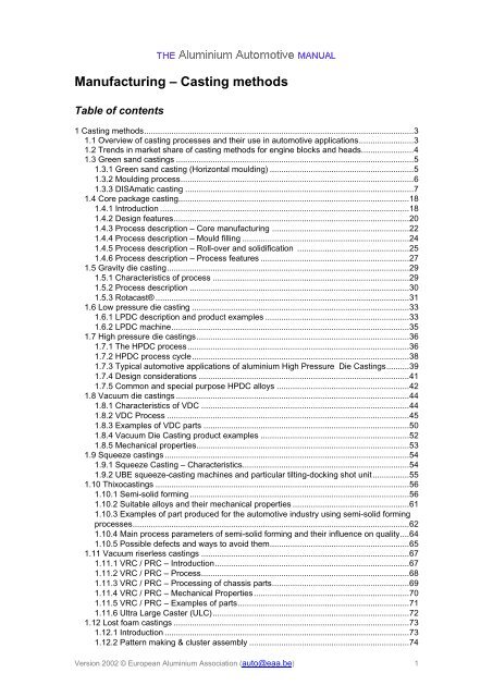
<strong>Manufacturing</strong> <strong>–</strong> <strong>Casting</strong> <strong>methods</strong><br />
Table of contents<br />
1 <strong>Casting</strong> <strong>methods</strong> ...................................................................................................................... 3<br />
1.1 Overview of casting processes and their use in automotive applications ........................ 3<br />
1.2 Trends in market share of casting <strong>methods</strong> for engine blocks and heads ....................... 4<br />
1.3 Green sand castings ........................................................................................................ 5<br />
1.3.1 Green sand casting (Horizontal moulding) ............................................................... 5<br />
1.3.2 Moulding process ...................................................................................................... 6<br />
1.3.3 DISAmatic casting .................................................................................................... 7<br />
1.4 Core package casting..................................................................................................... 18<br />
1.4.1 Introduction ............................................................................................................. 18<br />
1.4.2 Design features ....................................................................................................... 20<br />
1.4.3 Process description <strong>–</strong> Core manufacturing ............................................................ 22<br />
1.4.4 Process description <strong>–</strong> Mould filling ......................................................................... 24<br />
1.4.5 Process description <strong>–</strong> Roll-over and solidification ................................................. 25<br />
1.4.6 Process description <strong>–</strong> Process features ................................................................. 27<br />
1.5 Gravity die casting .......................................................................................................... 29<br />
1.5.1 Characteristics of process ...................................................................................... 29<br />
1.5.2 Process description ................................................................................................ 30<br />
1.5.3 Rotacast® ............................................................................................................... 31<br />
1.6 Low pressure die casting ............................................................................................... 33<br />
1.6.1 LPDC description and product examples ............................................................... 33<br />
1.6.2 LPDC machine ........................................................................................................ 35<br />
1.7 High pressure die castings ............................................................................................. 36<br />
1.7.1 The HPDC process ................................................................................................. 36<br />
1.7.2 HPDC process cycle ............................................................................................... 38<br />
1.7.3 Typical automotive applications of aluminium High Pressure Die <strong>Casting</strong>s .......... 39<br />
1.7.4 Design considerations ............................................................................................ 41<br />
1.7.5 Common and special purpose HPDC alloys .......................................................... 42<br />
1.8 Vacuum die castings ...................................................................................................... 44<br />
1.8.1 Characteristics of VDC ........................................................................................... 44<br />
1.8.2 VDC Process .......................................................................................................... 45<br />
1.8.3 Examples of VDC parts .......................................................................................... 50<br />
1.8.4 Vacuum Die <strong>Casting</strong> product examples ................................................................. 52<br />
1.8.5 Mechanical properties ............................................................................................. 53<br />
1.9 Squeeze castings ........................................................................................................... 54<br />
1.9.1 Squeeze <strong>Casting</strong> <strong>–</strong> Characteristics......................................................................... 54<br />
1.9.2 UBE squeeze-casting machines and particular tilting-docking shot unit ................ 55<br />
1.10 Thixocastings ............................................................................................................... 56<br />
1.10.1 Semi-solid forming ................................................................................................ 56<br />
1.10.2 Suitable alloys and their mechanical properties ................................................... 61<br />
1.10.3 Examples of part produced for the automotive industry using semi-solid forming<br />
processes ......................................................................................................................... 62<br />
1.10.4 Main process parameters of semi-solid forming and their influence on quality .... 64<br />
1.10.5 Possible defects and ways to avoid them ............................................................. 65<br />
1.11 Vacuum riserless castings ........................................................................................... 67<br />
1.11.1 VRC / PRC <strong>–</strong> Introduction ..................................................................................... 67<br />
1.11.2 VRC / PRC <strong>–</strong> Process ........................................................................................... 68<br />
1.11.3 VRC / PRC <strong>–</strong> Processing of chassis parts ............................................................ 69<br />
1.11.4 VRC / PRC <strong>–</strong> Mechanical Properties .................................................................... 70<br />
1.11.5 VRC / PRC <strong>–</strong> Examples of parts ........................................................................... 71<br />
1.11.6 Ultra Large Caster (ULC) ...................................................................................... 72<br />
1.12 Lost foam castings ....................................................................................................... 73<br />
1.12.1 Introduction ........................................................................................................... 73<br />
1.12.2 Pattern making & cluster assembly ...................................................................... 74<br />
Version 2002 © <strong>European</strong> <strong>Aluminium</strong> <strong>Association</strong> (auto@eaa.be) 1
1.12.3 Coating & embedding ........................................................................................... 76<br />
1.12.4 Pouring & finishing ................................................................................................ 77<br />
1.12.5 Advantages and disadvantages ............................................................................ 79<br />
1.13 Comparing casting techniques ..................................................................................... 81<br />
1.13.1 Comparing casting techniques for engine blocks and cylinder heads .................. 82<br />
Version 2002 © <strong>European</strong> <strong>Aluminium</strong> <strong>Association</strong> (auto@eaa.be) 2
1 <strong>Casting</strong> <strong>methods</strong><br />
1.1 Overview of casting processes and their use in automotive<br />
applications<br />
Automotive casting processes can be differentiated according to (A) mould filling and (B)<br />
moulding technologies. The following <strong>methods</strong> are described in this section and are ranked<br />
according to current usage in the fig. below:<br />
1) Green sand casting<br />
2) Modified DISAmatic casting<br />
3) Core package casting<br />
4) Gravity die casting<br />
5) Low pressure die casting<br />
6) High pressure die casting<br />
7) Vacuum die casting<br />
8) Squeeze casting<br />
9) Thixocasting<br />
10) Vacuum riserless casting<br />
11) Lost foam casting<br />
<strong>Casting</strong> <strong>methods</strong> ordered for casting and moulding technology, size shows market<br />
importance<br />
Source: VAW<br />
Version 2002 © <strong>European</strong> <strong>Aluminium</strong> <strong>Association</strong> (auto@eaa.be) 3
1.2 Trends in market share of casting <strong>methods</strong> for engine<br />
blocks and heads<br />
Source: VAW AP<br />
Source: VAW AP<br />
Version 2002 © <strong>European</strong> <strong>Aluminium</strong> <strong>Association</strong> (auto@eaa.be) 4
1.3 Green sand castings<br />
1.3.1 Green sand casting (Horizontal moulding)<br />
The traditional green sand casting process, combined with high-speed moulding lines, is a<br />
very flexible process with high productivity for the manufacture of aluminium castings.<br />
Automatic pattern-change stations enable complete sets to be changed within the cycle time.<br />
For automotive applications, the process is used to cast:<br />
Intake manifolds<br />
Oil pan housings<br />
Structural parts<br />
Chassis parts<br />
The photographs show a high-speed horizontal moulding line with typical examples of<br />
castings produced using this method.<br />
High-speed horizontal moulding line<br />
Green sand castings<br />
Version 2002 © <strong>European</strong> <strong>Aluminium</strong> <strong>Association</strong> (auto@eaa.be) 5
1.3.2 Moulding process<br />
Loose moulding sand is filled into the mould area formed by the pattern plate/pattern bolster,<br />
the mould box and the filling frame. Compressed air is then forced through the mould to<br />
compact the sand. The air flows through the sand from the back of the mould to the pattern<br />
and escapes through vents in the pattern plate. The air flow thus moves the sand into the less<br />
accessible regions of the pattern and greatly improves compaction.<br />
The final strength in the mould is achieved in a subsequent pressing stage by means of a<br />
fixed or flexible pressure plate, a water cushion or a multi-platen press. The pressure of the<br />
press, as well as the pressure and duration of the air flow, can be controlled. This enables<br />
optimum mould strengths tailored to the needs of the individual application.<br />
Seiatsu process<br />
Middle mould process<br />
Version 2002 © <strong>European</strong> <strong>Aluminium</strong> <strong>Association</strong> (auto@eaa.be) 6
1.3.3 DISAmatic casting<br />
Automated green sand casting: DISAmatic, AGSC<br />
Automated green sand casting offers a reasonable alternative to conventional die casting<br />
processes (high pressure / low pressure / vacuum-assisted or not). This holds for middle and<br />
high volume series, especially for automotive applications.<br />
<strong>Manufacturing</strong> in high pressure die casting is limited by wall-thickness and design. I.e.<br />
producing a complicated inner structure by using lost cores is still not economically feasible in<br />
this process. Low pressure die casting's productivity is limited by solidification time, leading to<br />
cycle times of typically several minutes. Automated green sand casting has no such limits.<br />
The original DISAmatic process was advanced by Alcoa for manufacturing of high-quality<br />
automotive castings. Alcoa's variant green sand casting is AGSC (Alcoa Green Sand<br />
<strong>Casting</strong>).<br />
Examples of AGSC castings<br />
From left: Heat Exchanger, Hat Profile, Brake Calipers, Knuckles<br />
Source: Alcoa<br />
Version 2002 © <strong>European</strong> <strong>Aluminium</strong> <strong>Association</strong> (auto@eaa.be) 7
DISAmatic casting<br />
The DISAmatic casting process is a container-less sand casting process. The mold is divided<br />
upright. Front and rear mold half are formed by the shaped faces of every sand block.<br />
Stacked on a conveyor belt, the pouring cavity is between two blocks each.<br />
Insertion of individual cores or whole core packets is possible and can be carried out in an<br />
automated manner. The finished molds are pushed forward when a new sand block is added.<br />
The existing plant can produce and fill up to 200 sand molds per hour. Other machines of<br />
this type can produce up to 420 molds per hour. By using multiple cavities for smaller parts an<br />
hourly output surpassing all other casting processes is achievable.<br />
The process was modified in particular with regard to form filling to ensure high-quality<br />
castings with excellent microstructure.<br />
AGSC molds on conveyor belt<br />
Source: Alcoa<br />
Version 2002 © <strong>European</strong> <strong>Aluminium</strong> <strong>Association</strong> (auto@eaa.be) 8
Influence of mold filling rate<br />
For a clean microstructure it is necessary to ensure non-turbulent mold filling in addition to<br />
using clean metal. The purification of the metal is implemented by permanent degassing and<br />
the use of filters. In order to prevent impurities during mold filling (in particular oxide<br />
inclusions), attention has to be paid to a uniform filling rate. If the mold filling rate exceeds a<br />
critical value, separation of metal drops or folding of the metal front occurs, leading to<br />
formation of additional oxides (see figures).<br />
Above: Separation of metal drops and folding of metal surface<br />
Below: If critical velocity is exceeded, metal drops separate<br />
Source: Alcoa<br />
The critical velocity of the melt v is determined by the balance between inner pressure and<br />
the surface tension which is formed by the specific surface energy and the radius of<br />
curvature of the surface r:<br />
Inner pressure = · v 2<br />
Surface tension = 2 / r<br />
Critical velocity = (2 / (r · ))^0.5<br />
For molten aluminum, the critical velocity is around 500 mm/s.<br />
In the case of gravity casting, a height of only 13 mm is sufficient to reach this speed. Model<br />
investigations on test plates by the University of Birmingham confirmed this result.<br />
The figure on the right shows the occurrence of oxide films and the bending strength in<br />
dependence of the velocity of filling for plates of 5 mm and 10 mm thickness, respectively. If<br />
the velocity of filling exceeds 500 mm/s oxides causing cracks are observed more frequently<br />
and the bending strength of the plates is dramatically reduced.<br />
Version 2002 © <strong>European</strong> <strong>Aluminium</strong> <strong>Association</strong> (auto@eaa.be) 9
Influence of Velocity of Filling on Oxide Formation and Bending Strength<br />
Source: Alcoa<br />
Version 2002 © <strong>European</strong> <strong>Aluminium</strong> <strong>Association</strong> (auto@eaa.be) 10
Mould filling by an electro-magnetic pump<br />
The consideration of the drop height makes using force of gravity for mold filling undesirable.<br />
Rather, an electro-magnetic pump is chosen which allows feeding fluid metal with a controlled<br />
rate. In this case, the mold filling does not require a constant mass flow over time but the<br />
pumping rate has to be adapted to the geometry of the part.<br />
The figure below shows anti-gravity mold filling with an electro-magnetic pump used in the<br />
AGSC process.<br />
Mold filling from below by means of an electro-magnetic pump<br />
Source: Alcoa<br />
Version 2002 © <strong>European</strong> <strong>Aluminium</strong> <strong>Association</strong> (auto@eaa.be) 11
Wendy system<br />
The figure below shows the mold filling rate for gravity and electro-magnetic pump in a<br />
schematic comparison. The so-called Wendy system (second figure) is used for the<br />
evaluation of the correct mass flow over time. Via detectors in a mold, the raising level of<br />
metal in the mold is recorded continuously.<br />
Comparison of Mold Filling by Gravitation vs. Electro-magnetic Pump<br />
The Pump Allows a Tailored Filling Curve<br />
Source: Alcoa<br />
Wendy System: Controled Mold Filling By Planning And Verfication<br />
Source: Alcoa<br />
Deviations from the planned filling curve lead to a patched curve (by means of a computer) for<br />
pump power over filling time. The optimum control curve is calcated in an iterative process.<br />
This curve is then used in the later production of the respective part in order to control the<br />
mold filling.<br />
Version 2002 © <strong>European</strong> <strong>Aluminium</strong> <strong>Association</strong> (auto@eaa.be) 12
AGSC characteristics leading to cost reductions<br />
Process characteristics of a DISAmatic machine type 2120 (as of 2002, other types are<br />
available):<br />
Plate size: 850 mm x 650 mm, usable area: 700 mm x 550 mm. The maximum form height is<br />
378 mm. The maximum part weight is 30 kg. The minimum wall thickness is 3 mm.<br />
Overview of the AGSC Process: Complete Control of Mold Filling Combined With High<br />
Productivity<br />
Source: Alcoa<br />
While there is no hard upper limit for wall thickness the process works best for wall thickness<br />
of up to approx. 35 mm. Over 35 mm, the advantages of the bigger mold area are minimised<br />
e.g. by bigger risers.<br />
The use of sand as a mold medium allows a high degree of freedom for design of highvolume<br />
parts. Since the tools only have contact with molding sand, wear is almost<br />
nonexistent. Therefore, the life of tools is a multiple of the life of ingot molds and die casting<br />
tools (approx. one million shots). This means that even for high volume parts, investments<br />
for replacement tools can be omitted frequently. In addition the tool costs are - compared to<br />
ingot molds and dies for die casting - smaller. The tool changing times are short, less than<br />
10 minutes. All this reduces costs significantly.<br />
Plastic tools for prototypes are possible. This means that prototypes can be produced in the<br />
final casting process - effectively speeding up the introduction of new products.<br />
Version 2002 © <strong>European</strong> <strong>Aluminium</strong> <strong>Association</strong> (auto@eaa.be) 13
Properties of castings<br />
Today (2001), the main alloy in production in AGSC is A356 (AlSi7Mg) in tempers -T6 and -<br />
T7. AGSC castings are weldable and heat treatable. The process makes it possible to keep<br />
very narrow tolerances. Parts which are inserted in vehicles are characterized by uncritical<br />
behaviour in crash.<br />
The figure below shows a bumper bracket (A356-T7) connecting the crash boxes of the<br />
Mercedes A-Class to the Längsträger. The controlled mold filling of AGSC leads to a very<br />
clean and dense microstructure.<br />
AGSC Bumper Bracket (A356-T7)<br />
The wall-thickness of this crash-relevant part varies between 3 mm and 6 mm<br />
Source: Alcoa<br />
Numerous (>500) tensile tests (section is 4.1 mm thick) lead to the following results for the<br />
bumper bracket:<br />
Typical (average) TYE: 199MPa, 144MPa, 11%<br />
95%-99% minimum TYE: 177MPa, 125MPa, 7%<br />
95%-90% minimum TYE: 188MPa, 136MPa, 9%<br />
Explanation of mechanical properties:<br />
TYE means three values from tensile tests: Ultimate Tensile Strength, Yield Strength (Rp0.2)<br />
and Elongation.<br />
Typical properties are average values and have no statistical assurance.<br />
95-99% minimum properties: 0.99 of the population of values is expected to be equal to or<br />
greater than this property value with 95% confidence.<br />
95-90% minimum properties: 0.90 of the population of values is expected to be equal to or<br />
greater than this property value with 95% confidence.<br />
In addition to very good mean values for elongation the standard deviations are small,<br />
demonstrating high stability of the process. The figure below compares AGSC with<br />
conventional sand casting.<br />
Version 2002 © <strong>European</strong> <strong>Aluminium</strong> <strong>Association</strong> (auto@eaa.be) 14
Comparison: Distribution of Rm, conventional sand casting vs. AGSC, schematically<br />
Source: Alcoa<br />
Cast suspension parts showed the following TYE values in T6: 271.3 MPa, 211 MPa, 8 %.<br />
(29 samples, thickness of sections 4-16 mm.)<br />
AGSC has demonstrated its suitability especially for automotive parts but also complex<br />
geometries like heat exchangers. Other examples: Gear parts, knuckles, wheels, calipers,<br />
guidance cases but also shock towers. Safety parts in particular gain by the high quality<br />
microstructure.<br />
Version 2002 © <strong>European</strong> <strong>Aluminium</strong> <strong>Association</strong> (auto@eaa.be) 15
AGSC <strong>–</strong> Product examples<br />
The pictures show examples of parts demonstrating design possibilities and productivity.<br />
Tunnel: Size 400 x 300 x 180 mm3, wall thickness 3 mm, weight 0.9 kg<br />
Source: Alcoa<br />
Tunnel: Size 400 x 300 x 180 mm3, wall thickness 3 mm, weight 0.9 kg<br />
Source: Alcoa<br />
Shock Tower: Size 450 x 400 x 250 mm3, wall thickness 3 mm, weight 3 kg<br />
Source: Alcoa<br />
Version 2002 © <strong>European</strong> <strong>Aluminium</strong> <strong>Association</strong> (auto@eaa.be) 16
Shock Tower: Size 450 x 400 x 250 mm3, wall thickness 3 mm, weight 3 kg<br />
Source: Alcoa<br />
Rotor, high volume possible:up to 2800 parts per hour<br />
Source: Alcoa<br />
Brake Caliper, high volume possible: up to 1200 parts per hour<br />
Source: Alcoa<br />
Casing, high volume possible: up to 1200 parts per hour<br />
Source: Alcoa<br />
Version 2002 © <strong>European</strong> <strong>Aluminium</strong> <strong>Association</strong> (auto@eaa.be) 17
1.4 Core package casting<br />
1.4.1 Introduction<br />
See also:<br />
AAM <strong>–</strong> Applications <strong>–</strong> 1 Power train > Engine > Cylinder block<br />
Literature:<br />
Smetan, H.: Kernpaketverfahren im <strong>Aluminium</strong>motorenguss, MTZ 61, 2000, No.10,<br />
P.712-715<br />
The core package casting process, where the entire sand mould consists of single sand<br />
cores, was industrially applied first in 1970 using low pressure filling by means of an<br />
electromagnetic pump. Due to low productivity, the process was restricted to low volume<br />
series. However, the increasing interest in the outstanding dimensional quality and possible<br />
complexity of the castings led to further developments and thus, (e.g.) the Core Package<br />
System (CPS ® ) has become an established casting process for the volume production of<br />
engine blocks within a short period of time.<br />
In the following screens, the process and design features of the core package<br />
casting process are described:<br />
Design features<br />
Core manufacturing<br />
Mould filling<br />
Roll-over and solidification<br />
Process features<br />
Core package for V6 engine block<br />
Source: VAW<br />
Version 2002 © <strong>European</strong> <strong>Aluminium</strong> <strong>Association</strong> (auto@eaa.be) 18
Partly assembled core package for a 4-cylinder engine block<br />
Source: VAW<br />
4-cylinder engine block produced with the CPS® process<br />
Version 2002 © <strong>European</strong> <strong>Aluminium</strong> <strong>Association</strong> (auto@eaa.be) 19
1.4.2 Design features<br />
The question, which casting process is optimal for a given product, depends, beside other<br />
factors, on the desired complexity of the casting. Like all precision sand casting processes,<br />
the core package casting process offers almost unlimited possibilities for product design, e.g.<br />
for engine block castings:<br />
Complicated oil galleries and pre-cast oil channels to feed the crankshaft bearings.<br />
Complex exhaust gas return systems.<br />
Secondary air ducts.<br />
1 mm thick cooling water passages between the cylinders (facilitated by micro-core<br />
technology).<br />
<strong>Casting</strong>-in of cylinder liners.<br />
Hang-on and functional parts, such as thermostat housing, oil filter flange and splash wall can<br />
be integrated into the engine block with the core package process.<br />
Furthermore, the process provides extensive design freedom, for example in the design of<br />
undercuts, to reduce weight through the use of additional cores and/ or cavities and curved<br />
ports.<br />
Different designs for oil gallery cores<br />
Source: VAW<br />
Example of a complex oil gallery core design<br />
Source: VAW<br />
Version 2002 © <strong>European</strong> <strong>Aluminium</strong> <strong>Association</strong> (auto@eaa.be) 20
Schematic diagram showing the economic relation- ship between complexity,<br />
production volume and casting process<br />
Sources: VAW<br />
Version 2002 © <strong>European</strong> <strong>Aluminium</strong> <strong>Association</strong> (auto@eaa.be) 21
1.4.3 Process description <strong>–</strong> Core manufacturing<br />
See also:<br />
AAM <strong>–</strong> Applications <strong>–</strong> 1 Power train > Engine > Cylinder block<br />
This process applies entirely resin bonded sand cores. Specifically, silica sand is used in the<br />
polyurethane cold-box process. The core package comprises also the whole running and<br />
feeding system. The core packages are, to a large extent, assembled automatically.<br />
Production lines with a capacity of up to 160 core packages per hour are currently in<br />
operation.<br />
Extremely tight tolerances are achievable, so that e.g. grey iron liners can be placed into the<br />
core package with a position tolerance of +-0.3 mm.<br />
Usually, the core packages are stored in a buffer and then fed into the casting line.<br />
Inserted parts such as grey iron liners can be preheated by induction coils in their final<br />
position in the core package prior to mould filling. This guarantees reproducible and<br />
repeatable conditions concerning the contact between the grey iron liners and the aluminium<br />
cast alloy.<br />
Fully automatic core package assembly with robots<br />
Source: VAW<br />
Version 2002 © <strong>European</strong> <strong>Aluminium</strong> <strong>Association</strong> (auto@eaa.be) 22
Manual assembly of core packages for enging block castings<br />
Source: VAW<br />
Version 2002 © <strong>European</strong> <strong>Aluminium</strong> <strong>Association</strong> (auto@eaa.be) 23
1.4.4 Process description <strong>–</strong> Mould filling<br />
See also:<br />
AAM <strong>–</strong> Applications <strong>–</strong> 1 Power train > Engine > Cylinder block<br />
Core packages from the buffer are flushed with inert gas and continuously fed into the casting<br />
line, allowing one casting every 20 seconds. This requires a continuous metal supply which<br />
is realised by means of a launder with a casting nozzle and a stopper rod.<br />
After an optional inductive pre-heating of grey iron liners, the core package is connected to<br />
the nozzle and the filling process is started by raising the stopper. The mould filling takes<br />
place through the feeder, which (only during filling) is located underneath the casting. The<br />
signal to stop mould filling is given by a control laser which detects the actual metal level.<br />
Process steps 1 to 4 ''filling the mould'' of the CPS process<br />
Source: VAW AG<br />
Version 2002 © <strong>European</strong> <strong>Aluminium</strong> <strong>Association</strong> (auto@eaa.be) 24
1.4.5 Process description <strong>–</strong> Roll-over and solidification<br />
Roll-over - Shortly after disconnecting from the metal supply position, the core package is<br />
rotated into the solidification position with the feeders now being on top of the casting.<br />
Rotating of the core package into the solidification position<br />
Source: VAW<br />
Solidification - The coldest metal which entered the mould first is now in a bottom position<br />
being in the greatest distance to the hot feeder and solidifies first. Hence, an optimal quasidirectional<br />
solidification towards the feeder takes place. However, due to the fact that, during<br />
filling the feeder necks are acting as gating, a compromise to find the best possible cross<br />
sections has to be made, to achieve both, a smooth filling and an optimal feeding.<br />
Quasi-directional solidification<br />
Source: VAW<br />
Version 2002 © <strong>European</strong> <strong>Aluminium</strong> <strong>Association</strong> (auto@eaa.be) 25
Simulation of temperature distribution during solidification<br />
Source: VAW<br />
Heat treatment - The core packages containing just solidified but still hot castings inside can<br />
be directly transferred into a heat treatment furnace, where they are de-cored and solution<br />
heat treated simultaneously in a very energy effective manner.<br />
Version 2002 © <strong>European</strong> <strong>Aluminium</strong> <strong>Association</strong> (auto@eaa.be) 26
1.4.6 Process description <strong>–</strong> Process features<br />
See also:<br />
AAM <strong>–</strong> Applications <strong>–</strong> 1 Power train > Engine > Cylinder block > Requirements for<br />
aluminium cylinder blocks<br />
Literature:<br />
Heusler, L.; Feikus, F.J.; Otte, M.O.: Alloy and <strong>Casting</strong> Process Optimisation for<br />
Engine Block Application. Proc. Conf. 105th AFS <strong>Casting</strong> Congress, Aluminum<br />
Division, 2001, Dallas, Texas, AFS, Des Plaines<br />
Feikus, F.J.: Optimierung einer AlSi-Gusslegierung und anwendungsorientierte<br />
Entwicklung der Gießtechnik zur Herstellung hochbelasteter Motorblöcke. Giesserei<br />
88, 2001, No.11, p.25-32<br />
There are two principal ways to place an engine block into the core package:<br />
1. Filling and feeding via the oil pan flange and optional additionally via the main bearing<br />
saddles. In this case, a chill cooling may be applied on the joint face providing an optimised<br />
directional solidification and a fine microstructure in the chilled area. This in turn, improves the<br />
mechanical properties in terms of elongation and tensile strength.<br />
2. Filling and feeding via the joint face with optional chill cooling on the main bearing saddles.<br />
This configuration is chosen, when good static and dynamic strength is required in the main<br />
bearings.<br />
Version 1: Filling and feeding via oil pan flange, chill cooling on joint face<br />
Source: VAW<br />
Version 2002 © <strong>European</strong> <strong>Aluminium</strong> <strong>Association</strong> (auto@eaa.be) 27
Version 2: Filling and feeding via joint face, chill cooling on main bearing saddles<br />
Source: VAW<br />
The dendritic microstructure of a casting influences its mechanical properties and is<br />
strongly depending on the cooling rate in the considered area. The distance between<br />
secondary dendrite arms (DAS) depends on the local solidification time and is therefore a<br />
means to check the cooling conditions, s. fig. below.<br />
Dendrite arm spacings depending on chill position (feeding from the oposite side)<br />
Source: VAW<br />
Version 2002 © <strong>European</strong> <strong>Aluminium</strong> <strong>Association</strong> (auto@eaa.be) 28
1.5 Gravity die casting<br />
1.5.1 Characteristics of process<br />
Gravity die casting is one of the standard processes for the manufacture of high-integrity<br />
automotive castings. It represents proven and absolute precision technology for the<br />
production of large batch quantities. This process is used in carousel casting units or in<br />
shuttle technique particularly for the manufacture of engine castings.<br />
Optimum heat dissipation from the solidifying casting through the die leads to short<br />
solidification times. This results in castings which have good mechanical properties,<br />
especially after an additional heat treatment.<br />
1, 2 - Carousel casting unit<br />
3 - Cylinder-head GM<br />
4 - Engine block VW-Lupo<br />
Source: VAW AG<br />
In addition to producing ever more complicated cylinder heads for petrol and diesel engines,<br />
gravity die casting is also used for the manufacture of diesel engine blocks with cast-in grey<br />
iron liners.<br />
Version 2002 © <strong>European</strong> <strong>Aluminium</strong> <strong>Association</strong> (auto@eaa.be) 29
1.5.2 Process description<br />
In gravity die casting processes, the melt is metallurgically treated in the holding furnace,<br />
which is positioned near the dies.<br />
The quantity of melt for one casting is transported in a ladle and poured into the riser system<br />
of the mould by tilting the ladle. The melt fills the mould cavity smoothly from the bottom up<br />
until it appears in the risers positioned above the casting.<br />
In the example shown, i.e. the casting of a cylinder head, the mould filling and solidification<br />
conditions can be influenced by the design of the gating system and the risers in the top core.<br />
Directional solidification can be forced by using water cooling in the bottom of the die<br />
(combustion chamber area of the head).<br />
Tridem<br />
Gravity die casting process<br />
Version 2002 © <strong>European</strong> <strong>Aluminium</strong> <strong>Association</strong> (auto@eaa.be) 30
1.5.3 Rotacast ®<br />
Rotacast ® is a new type of casting process*) based on permanent mould casting. This process<br />
meets the most exacting requirements and has now been introduced for the volume<br />
production of cylinder heads.<br />
Rotacast ® procedure: cores are inserted in the mould, the die is closed and rotated 180°<br />
around its long axis. In this way, the combustion chamber of the die cavity shoots upwards. In<br />
the top core, the gating system comprises the whole length of the cylinder head. A tundish,<br />
which is filled with molten metal and connected firmly to the die, docks tightly with the top core<br />
from below. To fill the die with melt, the die and tundish are rotated together around the long<br />
axis in a numerically controlled process. This ensures that the metal fills the die cavity<br />
smoothly in laminar flow. Due to the large gating cross-section, high filling speeds are<br />
avoided. The die cavity is thus filled free of turbulence.<br />
*) developed by VAW aluminium AG<br />
Rotacast process scheme<br />
Source: VAW AG<br />
The gating system can be laid out in the top core in accordance with the respective geometry<br />
of the casting. Changes can also be made relatively easily. The venting of the die cavity and<br />
the escape of the core gases take place via the melt-free passages in the top core directly<br />
into the tundish or via the die joint and core prints.<br />
Through laminar flow die filling, local overheating due to so-called "channelling effects" <strong>–</strong><br />
preferred flow path taken by the melt <strong>–</strong> is prevented.<br />
The melt flows from the tundish into the die cavity and reaches its final solidification position<br />
via the shortest route.<br />
The solidification process already begins on the bottom plate during die filling <strong>–</strong> very high<br />
cooling rates are achieved <strong>–</strong> and slows in the area of the core-sand riser. The efficiency of the<br />
riser is improved when it is subsequently filled with hot melt directly from the tundish.<br />
Similarly, the build-up of less overpressure in the tundish after reaching the solidification<br />
position also has positive effects.<br />
With Rotacast ® die casting, die filling and solidification can be optimally directed and<br />
customised material properties achieved.<br />
Rotacast ® castings display a very fine-grained cast structure with low porosity, especially in<br />
the combustion chamber area of cylinder heads. They offer great potential for the<br />
manufacture of "tailored castings" with the aid of well-devised die cooling technology,<br />
optimised alloys and subsequent heat treatment.<br />
Version 2002 © <strong>European</strong> <strong>Aluminium</strong> <strong>Association</strong> (auto@eaa.be) 31
Rotacaster<br />
Source: VAW AG<br />
Production line Rotacast ® : closed die with inserted cores before rotation into casting<br />
position.<br />
Version 2002 © <strong>European</strong> <strong>Aluminium</strong> <strong>Association</strong> (auto@eaa.be) 32
1.6 Low pressure die casting<br />
1.6.1 LPDC description and product examples<br />
Cylinder head, Low pressure die casting<br />
Low pressure die casting is a well-known casting process, especially for aluminium wheels<br />
in passenger cars. The process is also used in the production of big V-engine blocks in<br />
hypereutectic aluminium alloys and in the casting of air-cooled cylinder heads for motor<br />
cycles. Mould filling is controlled by regulating the pressure in the casting furnace. The melt<br />
flows through the riser tube which is positioned under the melt surface of the furnace and fills<br />
the mould very smoothly with clean melt from the bottom up. After mould filling, solidification<br />
starts from the opposite end of the mould in the direction of the tube. By increasing the<br />
pressure in the casting furnace, good feeding is guaranteed. Cycle times are long due to the<br />
fact that the casting is connected to the big melt volume by the riser tube during solidification.<br />
Version 2002 © <strong>European</strong> <strong>Aluminium</strong> <strong>Association</strong> (auto@eaa.be) 33
LPDC cast ''BBS Challenge'' wheel<br />
LPDC cast V-8 cylinder block<br />
Version 2002 © <strong>European</strong> <strong>Aluminium</strong> <strong>Association</strong> (auto@eaa.be) 34
1.6.2 LPDC machine<br />
With active water or air-cooling channels in the mould, the thermal conditions can be<br />
influenced during solidification.<br />
Directional solidification and increased pressure lead to small riser volumes. This effect can<br />
be seen in the pictures of the two wheels below:<br />
Top - Low pressure die casting<br />
Bottom - Gravity die casting<br />
LPDC wheel as cast, note small riser at hub center<br />
Source: VAW<br />
Gravity Die Cast wheel, note large risers at rim and center hub<br />
Source: VAW<br />
The casting unit of a low-pressure machine consists of a pressure-tight holding furnace, the<br />
pressure control unit, the hydraulic die manipulators and usually one die for the casting.<br />
LPDC casting machine and furnace<br />
Source: Kutz<br />
Version 2002 © <strong>European</strong> <strong>Aluminium</strong> <strong>Association</strong> (auto@eaa.be) 35
1.7 High pressure die castings<br />
1.7.1 The HPDC process<br />
Filling speed and intensification pressure differentiates high-pressure die casting<br />
from most other casting processes.<br />
After liquid metal is transferred to the shot sleeve (s. fig. below), the plunger slowly<br />
closes to shut-off the filling port.<br />
Schematic drawing of a typical cold-chamber diecasting machine<br />
This is the only HPDC-type used with aluminium<br />
The plunger is then moved towards the die at a controlled but high speed in order to<br />
fill the die cavity.<br />
With the potential for highly automated operation, the high-pressure die casting<br />
(HPDC) process is capable of extremely high levels of productivity.<br />
HPDC machines are size rated by the closing force (s. figs.)<br />
HPDC machines:<br />
5.4 MN (above),<br />
35 MN (below).<br />
Photograph of a fairly common 600 ton (5400kN) diecast machine<br />
Source: IdraPrince<br />
Version 2002 © <strong>European</strong> <strong>Aluminium</strong> <strong>Association</strong> (auto@eaa.be) 36
This 4000 ton (35MN) machine is close to the upper end of available size ranges<br />
Source: IdraPrince<br />
Version 2002 © <strong>European</strong> <strong>Aluminium</strong> <strong>Association</strong> (auto@eaa.be) 37
1.7.2 HPDC process cycle<br />
Process cycle (s. schemes below):<br />
Schematic Plunger velocity-time and pressure-time curves<br />
The pressure cycle in a modern HPDC machine is closely controlled in all stages.<br />
Filling times are typically on the order of 10-25 milliseconds.<br />
Once the die is filled, pressures, which may exceed 70 MPa, are maintained on the<br />
casting, using an accumulator, until solidification is complete (third stage, at right)<br />
With the potential for highly automated operation, the high-pressure die<br />
casting process is capable of extremely high levels of productivity.<br />
Multiple hydraulic circuits are used depending on the plunger speed needed at each<br />
stage as shown below.<br />
Version 2002 © <strong>European</strong> <strong>Aluminium</strong> <strong>Association</strong> (auto@eaa.be) 38
1.7.3 Typical automotive applications of aluminium High Pressure<br />
Die <strong>Casting</strong>s<br />
Transmission cases are one of the largest automotive parts commonly diecast<br />
The common size range and close tolerances have been used to good effect in defining the<br />
hydraulic network in large transmission cases shown above. The Belt Tensioners (below) are<br />
typical of small die cast parts:<br />
Roughly 200g in weight, these belt tensioners are amongst the smaller automotive die<br />
castings<br />
Productivity for small parts like this is usually enhanced via multi-cavity die designs, e.g. 4 to<br />
8 cavities per die.<br />
Production rates are up to 100 parts per hour per cavity.<br />
To be die cast, engine blocks must designed with an open deck<br />
Version 2002 © <strong>European</strong> <strong>Aluminium</strong> <strong>Association</strong> (auto@eaa.be) 39
Source: Teksid Aluminum Ltd.<br />
Cast-in and mechanically locked steel inserts such as those in this engine block skirt<br />
are easy when die cast<br />
Version 2002 © <strong>European</strong> <strong>Aluminium</strong> <strong>Association</strong> (auto@eaa.be) 40
1.7.4 Design considerations<br />
Low magnification view of a section through a typical die cast part<br />
Physical design considerations:<br />
Only straight steel core pulls can be used to define internal passages.<br />
Core pulls increase tooling costs.<br />
Sand coring is generally not possible.<br />
Inserts can frequently be cast into the part. Hollow tubes, threaded inserts to fill out<br />
bosses, engine bore liners, and wear resistant inserts are common.<br />
Feeding of shrinkage is via the gates alone; parts should be designed with as uniform<br />
a thickness as possible.<br />
Metallurgical design considerations:<br />
Part ductility is limited by process considerations to
1.7.5 Common and special purpose HPDC alloys<br />
Al18Si (AA 391) Hypereutectic, Parent Alloy, 2-Stroke Engine Bore<br />
Source: Mercury Marine Ltd.<br />
Macro section showing entrained air frozen into a high pressure die cast part<br />
Entrained Air makes HPDC parts non-heat treatable. Air bubbles entrapped under high<br />
pressure during solidification will cause HPDC parts to blister during solutionising.<br />
Common Al Die casting Alloys:<br />
AlSi8Cu3 (AA 380)<br />
Rp0.2%=160 MPa, Rm =325 MPa, A5=0.5-3%<br />
AlSi10Cu (AA 383)<br />
Rp0.2%=150 MPa, Rm =310 MPa, A5=1-3%<br />
These are the most common alloys in use for general-purpose die castings.<br />
General utility castings, transmission cases, blocks etc.<br />
Caution: HPDC Properties are very process/part dependent; only typical as-cast values<br />
are shown.<br />
Version 2002 © <strong>European</strong> <strong>Aluminium</strong> <strong>Association</strong> (auto@eaa.be) 42
Al18Si (AA 391) Alloy Microstrucuture - Primary Si Imparts Wear Resistance<br />
Source: Mercury Marine Ltd.<br />
Typical AlSi8Cu (AA 380 microstructure), Hypoeutectic Al-Si plus Fe phases<br />
Special Purpose Al Die casting Alloys<br />
AlSi5 (AA C443)<br />
Rp0.2%=110 MPa, Rm =230 MPa, A5=9%<br />
Where exceptional ductility at moderate strength is required. Increased corrosion resistance<br />
(low Cu). (eg. steering wheels)<br />
AlSi12 (AA 413)<br />
Rp0.2%=140 MPa, Rm =300 MPa, A5=0.5-2%<br />
For intricate thin castings.<br />
AlSi17Cu4Mg (AA 390)<br />
Rp0.2%=240 MPa, Rm=280 MPa, A5=1%<br />
A hypereutectic wear-resistant alloy. Used for parent bore engine blocks, compressor parts,<br />
pulleys, brake shoes.<br />
Version 2002 © <strong>European</strong> <strong>Aluminium</strong> <strong>Association</strong> (auto@eaa.be) 43
1.8 Vacuum die castings<br />
1.8.1 Characteristics of VDC<br />
<strong>Aluminium</strong>-intensive cars like Audi A2, Audi A8 or Ferrari Modena rely heavily on Vacuum Die<br />
<strong>Casting</strong> (VDC) for the space frame design. VDC has several characteristics that make it<br />
highly attractive for automotive applications:<br />
thin walls in large structures: Designs using a minimum wall thickness well below 2<br />
mm.<br />
joining with standard welding techniques as well as Laser welding and self-piercing<br />
rivets.<br />
crash worthy structures (i.e. A-pillar of Audi A2, frame Ferrari Modena)<br />
wide selection of alloys including heat treatable and non-heat treatable alloys.<br />
high productivity.<br />
Space Frame of Ferrari 360 Modena using large VDC shock towers<br />
Source: Alcoa<br />
Müller-Weingarten vacuum die caster, closing force: 4400 metric tons<br />
Source: Alcoa<br />
Version 2002 © <strong>European</strong> <strong>Aluminium</strong> <strong>Association</strong> (auto@eaa.be) 44
1.8.2 VDC Process<br />
Vacuum Dies<br />
The principle of vacuum die casting requires the dies to be very tight. Residual pressure is as<br />
low as 20 - 30 hPa. (Normal atmospheric pressure is 1013 hPa). Therefore tools consist of<br />
frames and one or several inserts with air seals in between. Good quality tools loose less than<br />
1.5 hPa/s of vacuum.<br />
Melt<br />
The melt is kept in the dosage furnace below the filling chamber. Melt cleanness determines<br />
heat treatability as well as weldability of castings. If the gas content is too high, heat treatment<br />
produces humps on the surface, also called blisters.<br />
Vacuum Die <strong>Casting</strong> Step 1: Dosage<br />
In this step the low air pressure in the filling chamber sucks a portion of melt into the filling<br />
chamber. The amount of metal can be adjusted.<br />
1. Step: Dosage, suction of metal into the feeding chamber<br />
Source: Müller-Weingarten<br />
2. Metal Transport:<br />
The piston drives up and seals the suction pipe. The melt is pressed to the gate. Metal<br />
velocity in this phase is low.<br />
2. Step: Transport of metal to the gate<br />
Source: Müller-Weingarten<br />
Version 2002 © <strong>European</strong> <strong>Aluminium</strong> <strong>Association</strong> (auto@eaa.be) 45
3. Injection:<br />
After the vacuum valves are closed the melt is injected into the die at high rate. During the<br />
"shot", metal velocity is high.<br />
3. Step: Injection<br />
Source: Müller-Weingarten<br />
4. Post injection densification:<br />
After injection the piston exerts high pressure (> 150 bar) until complete solidification. This<br />
leads to a dense microstructure.<br />
4. Step: Post Injection Pressure, important to prevent blisters in heat treatment &<br />
guarantee weldability<br />
Source: Müller-Weingarten<br />
Process Control:<br />
Modern die casters allow controlling and documenting up to 40 parameters per shot. This<br />
allows precise control and high reproducibility.<br />
Version 2002 © <strong>European</strong> <strong>Aluminium</strong> <strong>Association</strong> (auto@eaa.be) 46
Shot control using defined parameters<br />
Source: Alcoa<br />
1: Müller-Weingarten Vacuum Die <strong>Casting</strong> machine, closing force 4400 metric tons<br />
Source: Alcoa Soest, Germany<br />
2: The opened mold is sprayed with mold release agent by a robot<br />
Source: Alcoa<br />
Version 2002 © <strong>European</strong> <strong>Aluminium</strong> <strong>Association</strong> (auto@eaa.be) 47
3: After the mold is closed, the piston injects liquid aluminium into the mould (Shot)<br />
Source: Alcoa<br />
4: Part is ejected and removed by another robot.<br />
Source: Alcoa<br />
5: Water quench right after removal (air quench is also possible)<br />
Source: Alcoa<br />
Version 2002 © <strong>European</strong> <strong>Aluminium</strong> <strong>Association</strong> (auto@eaa.be) 48
6: Part is now cool and ready for further processing: deburring, heat treatment,<br />
machining etc.<br />
Source: Alcoa<br />
Version 2002 © <strong>European</strong> <strong>Aluminium</strong> <strong>Association</strong> (auto@eaa.be) 49
1.8.3 Examples of VDC parts<br />
Ferrari Modena Spaceframe: light colored nodes are produced in AVDC<br />
Source: Alcoa<br />
A-Post<br />
Source: Alcoa<br />
B-Post DC S-Class Coupe<br />
Source: Alcoa<br />
Version 2002 © <strong>European</strong> <strong>Aluminium</strong> <strong>Association</strong> (auto@eaa.be) 50
Shock tower Audi A8<br />
Source: Alcoa<br />
A8 Lower A-Post Audi A8<br />
Source: Alcoa<br />
Version 2002 © <strong>European</strong> <strong>Aluminium</strong> <strong>Association</strong> (auto@eaa.be) 51
1.8.4 Vacuum Die <strong>Casting</strong> product examples<br />
Audi A2 Space Frame: colours indicate different processes<br />
Audi A2: High-Q-Cast "B-pillar"<br />
Assembly from the front area of Audi A2 Space Frame<br />
Version 2002 © <strong>European</strong> <strong>Aluminium</strong> <strong>Association</strong> (auto@eaa.be) 52
1.8.5 Mechanical properties<br />
*The table gives typical and minimum mechanical properties for two alloys in production in<br />
Alcao's plant in Soest, Germany.<br />
AlMg3Mn is a non-heat treatable alloy with ca. 3.5 % Magnesium and 1.3 % Manganese. This<br />
alloy is based on solid-solution strengthening, hence no heat treatment required.<br />
AlSi9Mg is a heat treatable alloy with ca. 10 % Silicon and 0.2 % Magnesium. This alloy is<br />
precipitate-hardened (Mg2Si) and requires a heat treatment of solid solution, subsequent<br />
quenching and ageing.<br />
Both alloys are low on Iron and Copper.<br />
Source: Alcoa<br />
Version 2002 © <strong>European</strong> <strong>Aluminium</strong> <strong>Association</strong> (auto@eaa.be) 53
1.9 Squeeze castings<br />
1.9.1 Squeeze <strong>Casting</strong> <strong>–</strong> Characteristics<br />
What is Squeeze casting?<br />
This technique was initially similar to forging, with a mould made of a hollow lower dye and an<br />
upper dye used as a stamp, which are set on a drop forging press. And the press is started as<br />
soon as the liquid metal is poured in the lower dye.<br />
This method is no more widely used, if ever, as 2 problems rise: the thickness of the cast part<br />
depends on the quantity of metal poured; and parts must be of rather uniform thickness,<br />
unless thinner areas, which solidify before thicker ones, will prevent pressure from applying<br />
any more on areas subject to shrinkage.<br />
As a matter of fact, "squeeze-casting", which is then sometimes said "indirect" SC, is now<br />
commonly an evolution of pressure die casting, using the same machines, with differences<br />
only on the injection speed and on the design of the pouring system:<br />
the speed of the metal is drastically lowered, so as to avoid any turbulence <strong>–</strong> typically<br />
0.5 m/s, against 30 to 60 m/s in HPDC <strong>–</strong> ;<br />
the solidification must be progressive from the thinner area of the cast part to the<br />
biscuit.<br />
In other words the channels must be thicker than the cast part, and the gates set so as to<br />
feed any area.<br />
The high cooling speed and the pressure applied give the parts excellent mechanical<br />
properties, and squeeze casting is therefore particularly suitable for suspension parts.<br />
Version 2002 © <strong>European</strong> <strong>Aluminium</strong> <strong>Association</strong> (auto@eaa.be) 54
1.9.2 UBE squeeze-casting machines and particular tilting-docking<br />
shot unit<br />
The "indirect" squeeze casting technique is widely used in the USA and, above all, in Japan,<br />
where the machine maker UBE has developed a particular technique of tilting sleeve, using<br />
either vertical or horizontal presses.<br />
Version 2002 © <strong>European</strong> <strong>Aluminium</strong> <strong>Association</strong> (auto@eaa.be) 55
1.10 Thixocastings<br />
1.10.1 Semi-solid forming<br />
A process at the border between casting and forming<br />
This process makes use of the thixotropic behaviour of semi-solid metallic alloys. Under some<br />
conditions the metal behaves like a solid (high viscosity) if not sheared. As soon as shearing<br />
occurs, viscosity decreases by orders of magnitude. Under some conditions this effect is<br />
reversible.<br />
Source: JP Gabathuler, Alcan<br />
Metallic alloys have strong thixotropic behaviour if:<br />
it is possible to bring the metal homogeneously to the required semi-solid state, i.e.<br />
enough solidification range is present,<br />
a microstructure with very fine and round grains exists.<br />
Source: JP Gabathuler, Alcan<br />
Version 2002 © <strong>European</strong> <strong>Aluminium</strong> <strong>Association</strong> (auto@eaa.be) 56
Main processes used today in production<br />
All semi-solid forming processes are characterised by:<br />
10 to 70% solid phase during forming,<br />
Thixotropic properties: initially the metal's viscosity is high. After being sheared its<br />
viscosity decreases strongly.<br />
the metal solidifies during forming.<br />
Specific properties of the products:<br />
Since only part of the metal is liquid, shrinkage porosity is reduced.<br />
Solidification takes place very rapidly and little heat extraction is necessary.<br />
Since the viscosity of the metal is high, mould filling occurs in a very laminar way.<br />
Net-shape parts can be produced.<br />
Thixocasting: Liquid metal is first DC-cast to fine grained billets which are then reheated to<br />
the semi-solid state and formed to the final product. This process has been mainly used<br />
during the last 20 years.<br />
Process steps of Thixocasting<br />
Source: Alcan<br />
Version 2002 © <strong>European</strong> <strong>Aluminium</strong> <strong>Association</strong> (auto@eaa.be) 57
Rheocasting: Liquid metal is directly cooled down to the semi-solid state and processed to<br />
the final product. Since 1999, this process family is gaining new attention.<br />
Process steps of Rheocasting<br />
Source: Alcan<br />
Version 2002 © <strong>European</strong> <strong>Aluminium</strong> <strong>Association</strong> (auto@eaa.be) 58
Metallurgical aspects of semi-solid processes<br />
Thixocasting<br />
The metal used has to show very fine and spherical grains to increase the shear thinning<br />
effect during forming.<br />
DC-casting is normally combined with strong electromagnetic stirring. This leads to<br />
fine rosette like grains (fig. below),<br />
Microstructure of AlSi7Mg0.3 before re-heating<br />
Source: Alcan<br />
During re-heating the metal, grains become spherical, as required for semi-solid<br />
forming (fig. below),<br />
Microstructure of AlSi7Mg0.3 after re-heating<br />
Source: Alcan<br />
During forming, the weak bridges between the grains break, leading to a strong reduction of<br />
viscosity (shear thinning).<br />
Rheocasting<br />
During cooling the liquid to the semi-solid state, some specific conditions have to be fulfilled to<br />
get the fine grains required.<br />
A very high amount of grain seeds have to be built. This can be produced by using<br />
chemical grain refiners, suitable thermal conditions or mechanical vibrations in the<br />
melt,<br />
During the process of partial solidification, the many grain seeds grow and, after<br />
touching their neighbours, get spherical (fig. below).<br />
Version 2002 © <strong>European</strong> <strong>Aluminium</strong> <strong>Association</strong> (auto@eaa.be) 59
Microstructure of AlSiMg0.3 alloy ready for forming<br />
Source: Alcan<br />
Version 2002 © <strong>European</strong> <strong>Aluminium</strong> <strong>Association</strong> (auto@eaa.be) 60
1.10.2 Suitable alloys and their mechanical properties<br />
Requirements for alloys suitable for semi-solid forming:<br />
The metal can be brought homogeneously to a liquid fraction between 40 and 60%<br />
(i.e. no pure metal or eutectic alloy),<br />
The solid phase is prone to build a fine globular structure,<br />
The flow behaviour of the alloy is good.<br />
Static mechanical properties of AlSi7Mg0.3 (most used aluminium alloy) in various<br />
temper conditions<br />
Source: Alcan<br />
Fatigue properties of thixoforming samples, A356, T6-temper (R=-1)<br />
Version 2002 © <strong>European</strong> <strong>Aluminium</strong> <strong>Association</strong> (auto@eaa.be) 61
1.10.3 Examples of part produced for the automotive industry<br />
using semi-solid forming processes<br />
Examples of parts which have already been in production<br />
Master brake cylinder<br />
Wheels<br />
Fuel rails<br />
Version 2002 © <strong>European</strong> <strong>Aluminium</strong> <strong>Association</strong> (auto@eaa.be) 62
Examples of parts which are today<br />
in development<br />
Multilink suspension component<br />
Suspension part<br />
From left to right: steering knuckle, injection pump, space frame note<br />
Version 2002 © <strong>European</strong> <strong>Aluminium</strong> <strong>Association</strong> (auto@eaa.be) 63
1.10.4 Main process parameters of semi-solid forming and their<br />
influence on quality<br />
<strong>Casting</strong> speed<br />
It is important that the metal front stays together during mould filling. A too high speed can<br />
lead to turbulences and air entrapment. At too low speed mould filling could be incomplete.<br />
Geometry of the runner system<br />
Due to the fact that metal is already partly solid, thicker cross sections and short runners are<br />
necessary in comparison to die casting. Numerical simulation is a very valuable tool for<br />
designing runner systems.<br />
Die temperature<br />
To avoid cold shots, die temperature has to be high enough. Very often, die temperatures of<br />
200 - 250°C lead to good results.<br />
Die parting agent<br />
Main requirements on mould release agent are:<br />
Good separation between mould and metal;<br />
Good wetting and adhesion on the mould;<br />
Low gas production in contact with metal;<br />
Low build up on mould.<br />
Die venting<br />
The air in the mould cavity has to be evacuated during mould filling. This is achieved by<br />
venting slots positioned at places which are filled last. These slots should not be thicker than<br />
0.2 mm.<br />
Final metal pressure<br />
Due to the partly solid metal, the risk of shrinkage porosity or hot tears is limited. To avoid it<br />
completely, a high final pressure of 500 to 1500 bars is often necessary.<br />
Version 2002 © <strong>European</strong> <strong>Aluminium</strong> <strong>Association</strong> (auto@eaa.be) 64
1.10.5 Possible defects and ways to avoid them<br />
Defect Non-fills and cold shuts Gas porosity and blisters<br />
Possible main<br />
cause for defects<br />
Way to avoid<br />
defects<br />
Examples<br />
Solid fraction too high;<br />
mould filling speed too<br />
low; mould too cold.<br />
Increase liquid fraction;<br />
increase speed; heat<br />
mould more.<br />
Non-fills<br />
Source: EFU<br />
Defect Inclusions (mainly oxides)<br />
Possible main cause for<br />
defects<br />
Way to avoid defects<br />
Examples<br />
Defect Shrinkage porosity<br />
Possible main cause for<br />
defects<br />
Way to avoid defects<br />
Turbulent mould filling; runner's geometry<br />
not adequate; not enough venting; water<br />
in mould; die parting agent produces<br />
gases.<br />
Use smooth runners with cylindrical cross<br />
sections. If necessary, use vacuum.<br />
Gas porosity and blisters<br />
Source: Alcan<br />
Retention system for oxide skin of metal not efficient<br />
enough; two metal fronts hit together.<br />
Use and optimise oxide retention systems; fronts with<br />
oxides should be brought into overflows.<br />
Inclusions<br />
Source: Alcan<br />
Feeding of large cross sections is not good enough.<br />
Dimension runner and gating systems for good feeding;<br />
use numerical simulation to control and optimise them.<br />
Version 2002 © <strong>European</strong> <strong>Aluminium</strong> <strong>Association</strong> (auto@eaa.be) 65
Examples<br />
Defect Segregations<br />
Possible main cause for<br />
defects<br />
Way to avoid defects<br />
Examples<br />
Shrinkage porosity<br />
Source: EFU<br />
Geometry of channels, high flow velocities can lead to<br />
separations between solid and liquid phases.<br />
Increase mould filling speed gives often good results;<br />
improve channel's geometry (smoother flow path).<br />
Segregations<br />
Source: Alcan<br />
Version 2002 © <strong>European</strong> <strong>Aluminium</strong> <strong>Association</strong> (auto@eaa.be) 66
1.11 Vacuum riserless castings<br />
1.11.1 VRC / PRC <strong>–</strong> Introduction<br />
VRC / PRC is a combination of Vacuum Riserless <strong>Casting</strong> (VRC) with Pressure Riserless<br />
<strong>Casting</strong> (PRC) (fig.1). This variant of low pressure die casting has been developed by Alcoa<br />
mainly for automotive chassis parts.<br />
"Riserless" means no mechanical feeding of melt into the mould. In addition, the level of melt<br />
in the feeding furnace is kept constant by replacing every shot from a holding furnace.<br />
Furthermore, the direction of solidification is controlled by active heating and/or cooling.<br />
Thicker sections can be fed directly in most cases, leading to lean gating systems.<br />
VRC / PRC castings have a dense, fine grained microstructure with excellent mechanical<br />
properties.<br />
Fig. 1: Elements of Alcoa's VRC/PRC process, schematically<br />
Version 2002 © <strong>European</strong> <strong>Aluminium</strong> <strong>Association</strong> (auto@eaa.be) 67
1.11.2 VRC / PRC <strong>–</strong> Process<br />
Fig 2: VRC / PRC casting machine, schematically<br />
Source: Alcoa<br />
Fig. 3: VRC/PRC Gen III casting machine<br />
Source: Alcoa<br />
Version 2002 © <strong>European</strong> <strong>Aluminium</strong> <strong>Association</strong> (auto@eaa.be) 68
1.11.3 VRC / PRC <strong>–</strong> Processing of chassis parts<br />
Fig. 4 is a flow chart of chassis parts production using VRC / PRC. The alloy most commonly<br />
used for this process is A356 / AlSi7Mg. First, raw material is analysed metallurgically. After<br />
melting, liquid aluminium is distributed by a channel system feeding furnaces equipped with<br />
impellers. From there the melt flows to dosage furnaces feeding the casting furnaces after<br />
every shot.<br />
Fig 4: Flow chart of chassis parts production<br />
Source: Alcoa<br />
After solidification the chassis parts are removed either manually (small parts) or robotically<br />
(large, heavy parts). Sawing and deburring is usually automatized. This is followed by X-Ray<br />
with automatic image analysis, heat treatment to achieve suitable mechanical properties,<br />
crack detection, eventually machining and shipping.<br />
Version 2002 © <strong>European</strong> <strong>Aluminium</strong> <strong>Association</strong> (auto@eaa.be) 69
1.11.4 VRC / PRC <strong>–</strong> Mechanical Properties<br />
See also:<br />
AAM <strong>–</strong> <strong>Manufacturing</strong> <strong>–</strong> 1 <strong>Casting</strong> <strong>methods</strong> > Vacuum die castings > Mechanical<br />
properties<br />
AAM <strong>–</strong> <strong>Manufacturing</strong> <strong>–</strong> 1 <strong>Casting</strong> <strong>methods</strong> > Green sand castings<br />
Due to anti-gravity turbulance-free filling and directional solidification, the good microstructure<br />
leads to excellent mechanical properties. Some parts are used as cast, higher strength<br />
requirements are met after heat treatment.<br />
A356-F subframe A356-T64 knuckle<br />
as cast heat treated<br />
Yield strength 85 MPa 230 MPa<br />
(typical)<br />
Ultimate Strength 150 MPa 300 MPa<br />
(typical)<br />
Elongation 12 % 11 %<br />
(typical)<br />
Mechanical properties can be adjusted by heat treatment to meet various requirements.<br />
Fig. 5: Comparison of Alcoa's automotive-oriented casting processes VRC / PRC,<br />
AVDC and AGSC<br />
Version 2002 © <strong>European</strong> <strong>Aluminium</strong> <strong>Association</strong> (auto@eaa.be) 70
1.11.5 VRC / PRC <strong>–</strong> Examples of parts<br />
See also:<br />
AAM <strong>–</strong> Applications <strong>–</strong> 2 Chassis > Structure and components > Subframe / Rear axle<br />
Knuckles from Generation II Machine:<br />
A356 - T6<br />
UTS - 276 MPa<br />
YS - 207 MPa<br />
EL - 8%<br />
Source: Alcoa<br />
Subframe produced with VRC / PRC : this part is a one piece casting approx. 1200 mm<br />
wide<br />
Source: Alcoa<br />
Version 2002 © <strong>European</strong> <strong>Aluminium</strong> <strong>Association</strong> (auto@eaa.be) 71
1.11.6 Ultra Large Caster (ULC)<br />
The VRC process was developed by Alcoa during the 1950s. PRC was added during the<br />
1980s. The Ultra Large Caster has been built during a further development effort targeting<br />
large castings.<br />
Ultra Large Caster (ULC) at Alcoa Technical Center, Pittsburgh, PA<br />
The parts produced demonstrated the potential of the process: the tailgate weights 11 kg,<br />
replacing 11 stampings and reducing the weight by 25 % (at that time). Wall thickness was<br />
between 2.5 mm and 6 mm. The alloy in this case was A356-T5. Mechanical properties (TYE)<br />
were: 170 MPa, 130 MPa, 10 %.<br />
Molds for this machine can be as big as 3400 mm x 1700 mm. This allows using a two-out die<br />
for parts like the tailgate below.<br />
One piece tailgate produced by ULC<br />
Cycle time was 2 minutes: this makes ULC economically attractive<br />
Source: Alcoa<br />
Version 2002 © <strong>European</strong> <strong>Aluminium</strong> <strong>Association</strong> (auto@eaa.be) 72
1.12 Lost foam castings<br />
1.12.1 Introduction<br />
Lost Foam <strong>Casting</strong> (LFC) or expandable pattern casting (EPC) involves the replacement of<br />
a low density foam pattern by liquid metal. LFC offers the possibility of a direct production of<br />
nearly any complex geometry including complicated undercuts and cavities without tapers<br />
and the need for considerable finishing work. Compared to the conventional sand casting<br />
<strong>methods</strong> it has economical and ecological advantages.<br />
Initial applications of LFC have used patterns cut and milled from foam blocks to the same<br />
tolerances as conventional patterns. This process, called full mold process, was primarily<br />
used to produce large, one-only stamping dies in bonded sand. It is still used for rapid<br />
prototyping of intricate components or large castings.<br />
The actual LFC-process uses patterns of expandable polystyrene (EPS) for industrial<br />
applications. These patterns, directly foamed to shape, are immersed in a moulding box with<br />
binderless sand. The liquid metal, which is poured into the cups of the downsprues, vaporises<br />
the EPS pattern, which is precisely replaced by the metal. With the possibility of assembled<br />
patterns very complex shapes can be created and the castings can be reproduced with<br />
remarkable dimensional accuracy.<br />
The steps of the production process, its application potential and the properties of LFC<br />
castings are described in the following.<br />
Version 2002 © <strong>European</strong> <strong>Aluminium</strong> <strong>Association</strong> (auto@eaa.be) 73
1.12.2 Pattern making & cluster assembly<br />
Pattern making. The initial material required for pattern making is expandable polystyrene<br />
(EPS). First step in the LFC-process is the pre-expansion of EPS beads.<br />
After maturing the beads are blown into a mould forming the pattern sections. The mould is<br />
then steamed to expand the beads further and tightly fill the cavity of the mould. Hot steam<br />
and expansion of the beads causes them to weld together.<br />
Cluster assembly. Complicated parts including undercuts and hidden cavities cannot be<br />
moulded in one working step, but are assembled from pattern segments into a final pattern.<br />
Joining techniques used are gluing, heated platen welding and plugging. In order to increase<br />
the efficiency of the total process several patterns are combined into a cluster and supplied<br />
with a common gate system, also made of EPS.<br />
Pre-expansion unit<br />
Source: LWF/ZVG Paderborn<br />
Version 2002 © <strong>European</strong> <strong>Aluminium</strong> <strong>Association</strong> (auto@eaa.be) 74
Pattern molding unit<br />
Source: LWF/ZVG Paderborn<br />
Pattern assembly<br />
Source: BMW AG Landshut<br />
Cluster with two cylinder heads<br />
Source: BMW AG Landshut<br />
Version 2002 © <strong>European</strong> <strong>Aluminium</strong> <strong>Association</strong> (auto@eaa.be) 75
1.12.3 Coating & embedding<br />
Coating: The clusters are coated with a refractory coating layer by immersion in a water<br />
soluble ceramic slurry. The coating layer has the function of guiding the gasification process<br />
of the pattern and to form a barrier between the moulding material and the gas-filled bubble<br />
which exists between the still solid EPS-pattern and the intruding aluminium melt. After the<br />
coating has dried, a thin, hard and permeable coating remains. The coatings are typically<br />
applied to a foam cluster by dipping, spraying or pouring.<br />
Embedding in sand: After the coating has dried, the cluster is placed in a flask and backed<br />
up with unbonded quartz sand without chemical additives. The sand is compacted through<br />
vibration with various frequencies, which causes the sand to fill all hidden cavities of the<br />
patterns.<br />
Production steps<br />
Source: LWF/ZVG Paderborn<br />
Coating of a cluster with two cylinderheads<br />
Source: BMW AG Landshut<br />
Version 2002 © <strong>European</strong> <strong>Aluminium</strong> <strong>Association</strong> (auto@eaa.be) 76
1.12.4 Pouring & finishing<br />
Simplified decomposition of EPS during form filling<br />
Source: LWF/ZVG Paderborn<br />
Pouring: During the filling process the molten metal flows via the gate system into the EPSpatterns,<br />
which is gasified, filling up the cavity and replacing exactly the pattern geometry.<br />
During this stage it is important to avoid turbulences, support the casting cavity wall and to<br />
realise a progressive elimination of the foam pattern. The gas originating from EPS<br />
decomposition permeates the coating layer and escapes into the sand, possibly supported by<br />
an external vacuum (see schematic fig. above). Form filling velocity and type of metal flow,<br />
i.e. laminar or turbulent, determine the part's quality by influencing the amount of oxide<br />
inclusions and porosity. Specifically, the following sets of parameters have to be tuned to<br />
each other:<br />
permeability of coating,<br />
optional external vacuum,<br />
metal temperature,<br />
EPS-pattern density and type of adhesive,<br />
geometry of the gating / riser system and of the patterns.<br />
Dumping, quenching and trimmig:<br />
After solidification of the casting, the sand can be removed from the flask and be prepared for<br />
the following moulding. Clusters are quenched and knocked-off from the gate system. The<br />
castings are purged and controlled w.r.t. defects. In many applications the castings don't<br />
require any further mechanical finishing.<br />
Version 2002 © <strong>European</strong> <strong>Aluminium</strong> <strong>Association</strong> (auto@eaa.be) 77
Production steps<br />
Source: LWF/ZVG Paderborn<br />
Experimental foundry for lost foam casting at the University of Paderborn<br />
Pouring by hand for experimental or short runs<br />
Source: LWF/ZVG Paderborn<br />
Version 2002 © <strong>European</strong> <strong>Aluminium</strong> <strong>Association</strong> (auto@eaa.be) 78
1.12.5 Advantages and disadvantages<br />
Source: Albert Handmann<br />
Advantages:<br />
freedom of design, possibility to build-up complicated geometries by assemblies of<br />
several EPS parts,<br />
no draft angles necessary,<br />
no burrs, less cleaning of castings,<br />
reduction of amount of machining,<br />
binder-less recirculated sand,<br />
reduced environmental burden,<br />
potential for Rapid Prototyping,<br />
economicy,<br />
dimensional accuracy and less finishing work,<br />
no sand reclaiming system,<br />
long life of moulding tools for EPS patterns (up to 1 mio.),<br />
high productivity,<br />
high flexibility,<br />
good surface quality.<br />
Disadvantages:<br />
possible deformation of pattern during sand fill and compaction,<br />
possible entrapment of plastic residues caused by non-optimised gating systems,<br />
large number of process parameters need to be controlled for optimum form filling.<br />
Cylinder heads<br />
Source: BMW AG Landshut<br />
Version 2002 © <strong>European</strong> <strong>Aluminium</strong> <strong>Association</strong> (auto@eaa.be) 79
Source: Albert Handmann<br />
Version 2002 © <strong>European</strong> <strong>Aluminium</strong> <strong>Association</strong> (auto@eaa.be) 80
1.13 Comparing casting techniques<br />
Version 2002 © <strong>European</strong> <strong>Aluminium</strong> <strong>Association</strong> (auto@eaa.be) 81
1.13.1 Comparing casting techniques for engine blocks and<br />
cylinder heads<br />
Source: VAW AP<br />
Source: VAW AP<br />
Version 2002 © <strong>European</strong> <strong>Aluminium</strong> <strong>Association</strong> (auto@eaa.be) 82