Download PDF - Piano Technicians Guild
Download PDF - Piano Technicians Guild
Download PDF - Piano Technicians Guild

Create successful ePaper yourself
Turn your PDF publications into a flip-book with our unique Google optimized e-Paper software.
An International Non-Profit Organization of Registered <strong>Piano</strong> <strong>Technicians</strong><br />
Taylor Mackinnon, RPT<br />
President<br />
520 SE 29th Ave., Hillsboro, OR 97123<br />
(503) 846-1501<br />
E-mail: pres@ptg.org<br />
Richard Bittner, RPT<br />
Vice President<br />
519 Melody Ct., Royal Oak, MI 48073<br />
(248) 398-8721<br />
E-mail: vp@ptg.org<br />
Paul Monroe, RPT<br />
Secretary-Treasurer<br />
5200 Irvine Blvd., Sp. 310, Irvine, CA 92620<br />
(714) 730-3469<br />
E-mail: sec@ptg.org<br />
David P. Durben, RPT<br />
Immediate Past President<br />
2310 E. Romneya Dr., Anaheim, CA 92806<br />
(714) 491-7392<br />
E-mail: ipp@ptg.org<br />
Ruth B. Phillips, RPT<br />
Northeast Regional Vice President<br />
3096 Bristol Rd., Warrington, PA 18976<br />
(215) 491-3045<br />
E-mail: nervp@ptg.org<br />
Robert L. Mishkin, RPT<br />
Southeast Regional Vice President<br />
1240 NE 153rd St., N. Miami Beach, FL 33162<br />
(305) 947-9030<br />
E-mail: servp@ptg.org<br />
Jack R. Wyatt Sr., RPT<br />
South Central Regional Vice President<br />
2027 15th St., Garland, TX 75041<br />
(972) 276-2243 (H)<br />
(972) 278-9312 (W)<br />
E-mail: scrvp@ptg.org<br />
Robert S. Bussell, RPT<br />
Central East Regional Vice President<br />
224 West Banta Rd., Indianapolis, IN 46217<br />
(317) 782-4320<br />
E-mail: cervp@ptg.org<br />
Richard E. West, RPT<br />
Central West Regional Vice President<br />
1427 A St., Lincoln, NE 68502<br />
(913) 631-8227<br />
E-mail: cwrvp@ptg.org<br />
Larry Joe Messerly, RPT<br />
Western Regional Vice President<br />
2222 W. Montebello Ave., Phoenix, AZ 85015<br />
(602) 433-9386<br />
E-mail: wrvp@ptg.org<br />
Keith Eugene Kopp, RPT<br />
Pacific NW Regional Vice President<br />
61283 Killowan Lane, Bend, OR 97702<br />
(541) 388-3741<br />
E-mail: pnwrvp@ptg.org<br />
2 <strong>Piano</strong> <strong>Technicians</strong> Journal / November 2000<br />
Plates in Focus<br />
Steve Brady, RPT<br />
Journal Editor<br />
You may notice a special emphasis on piano plates in this issue; it’s no<br />
accident. Some time ago the PTG Board of Directors approached me with a<br />
special request: a “theme” issue dealing with plates. We had hoped to cover<br />
plates from all angles, from raw materials, to design and manufacture, to<br />
breakage and repair techniques. Of greatest concern, however, was the matter<br />
of liability. When a plate breaks, whose fault is it?<br />
While an article on plate manufacture was not forthcoming, we’ve<br />
covered most of the other bases. Don Galt’s excellent article gives as much<br />
detail about the raw materials – not just for plates but for many other iron<br />
and steel piano parts as well – as most of us will ever need. Although Jim<br />
Ellis analyzes a specific plate that broke because of poor design, he also<br />
provides numerous insights into what constitutes a good plate design. From<br />
Wilford Young comes a welding repair method that has proven effective over<br />
many, many years and retired engineer Richard Oliver Snelson describes a<br />
hybrid restoration combining a mechanical repair with welded<br />
reinforcements. Finally, we’ve addressed liability by relating a tale that<br />
desperately needs to be told. As Marnie Squire’s story unfolds we see clearly<br />
that the technical authorities are unanimous: tuning a piano cannot possibly<br />
break a healthy plate.<br />
Indeed, a healthy plate can withstand unspeakable acts. In “The Tuner’s<br />
Life,” Carman Gentile tells of one such experience. I can recall many other<br />
instances myself. For example, a panicked piano owner called me after she<br />
discovered that her 11-year-old son had industriously removed all the plate<br />
rim lags from her small Chickering grand. The piano was horrendously out<br />
of tune. After replacing the lag screws, I found that the tuning had improved<br />
somewhat and was able to perform an uneventful tuning.<br />
In my shop, a concert-grand plate fell some four inches to a concrete<br />
floor when one of the hoist cables slipped. The plate didn’t break and,<br />
although this happened nearly 20 years ago, the piano is still humming along<br />
happily.<br />
The late Don Galt once related to me that he had seen a six-foot grand<br />
tumble end-over-end down a flight of 30 steps when a rope the movers were<br />
using suddenly broke as the piano approached the landing. Broken plate? No.<br />
“In fact,” Don said, “it was still pretty much in tune when we set it up<br />
afterward.” And that piano is still in service more than 25 years later.
Iron, Steel & <strong>Piano</strong>s<br />
By Don Galt, RPT<br />
(Reprinted from the <strong>Piano</strong> <strong>Technicians</strong> Journal, April, 1970.)<br />
Editor’s Introduction<br />
Don Galt served as Technical Editor of this publication from 1969 until 1977. One of the many special<br />
things that Don brought to his work as a piano technician and his work with the Journal was his extensive<br />
knowledge of iron and steel, gained over many years in his previous life as a re-bar engineer at<br />
Bethlehem Steel. I am reprinting this article in its entirety, and in a sidebar I’ve included a brief question<br />
and answer in which Don replies to a reader’s query on responsibility for plates broken while tuning.<br />
This item appeared in the November, 1970 issue of PTJ, p.10. – SB<br />
There is little in the appearance of a piano to<br />
reveal the massive forces that its members exert<br />
on one another, without respite, through many<br />
decades of time. It is only when the instrument<br />
absorbs the energy of the musician, translates it and throws it<br />
back as sound energy at small or great dynamic levels that<br />
the magnitude of these forces is hinted at.<br />
Even so, the dynamism of the pianist and the stolidity of<br />
the piano foster the illusion that the former, rather than the<br />
latter, is actually the source of the sound.<br />
So perhaps it is natural that piano users are ignorant of,<br />
and even piano technicians sometimes take for granted, the<br />
highly stressed metallic members to which the modern<br />
piano largely owes its dynamic compass.<br />
To gain a little sympathetic understanding of these<br />
members, this paper attempts a short description of the<br />
important iron products used in piano building: their<br />
manufacture, their physical properties, and their reactions to<br />
the loads they are asked to carry in the piano.<br />
For the reader’s convenience the article is divided into<br />
the following sections:<br />
General Considerations<br />
Pig Iron — The Blast Furnace<br />
Gray Cast Iron — The Cupola<br />
Steel — Making the Material<br />
Steel — The Rolling Mill<br />
Steel — Wire Drawing<br />
The Iron - Iron Carbide System<br />
Testing & Properties<br />
The first five sections of the article, down through<br />
“Steel — The Rolling Mill,” are fairly general, but with<br />
occasional references to our special interests.<br />
The section on “Steel – Wire Drawing” gives a very<br />
brief description of this procedure, leaving out more than it<br />
tells (as does every part of the article).<br />
The last two sections entitled “The Iron — Iron<br />
Carbide System” and “Testing & Properties,” will probably<br />
make the greatest demands on the reader’s attention. The<br />
author hopes that this attention will be rewarded with an<br />
enlarged understanding of how these materials do their<br />
work in the piano. If any reader gives up and jumps off<br />
during “The Iron-Iron Carbide System,” I hope he or she<br />
will climb back aboard for “Testing & Properties.”<br />
General Considerations<br />
Pure elemental metallic iron is a rare thing outside of the<br />
laboratory and we never encounter it in pianos. The steel<br />
music wire and the gray cast-iron plates of pianos, as well as<br />
other familiar iron products such as structural steel, wrought<br />
iron, white cast iron and so on, are mixtures of iron and<br />
carbon, iron being by far the predominant ingredient. They<br />
are not chemical compounds, so their proportions and<br />
hence their properties can and do vary widely. If the carbon<br />
content is less than about two percent by weight, the<br />
material is called steel. If the carbon is more than two<br />
percent it is called cast iron. This two percent figure is not<br />
arbitrary, but we will not explore its significance at the<br />
moment. These terms illustrate the sort of paradox that can<br />
grow up on a subject when the usage develops gradually.<br />
Steel is defined as a mixture or alloy of iron and carbon, and<br />
yet what is called cast iron contains more carbon than steel<br />
does.<br />
In practice, most steels have well less than two percent<br />
carbon, and most cast irons have well more than that<br />
amount. Gray cast iron, as used in piano plates, contains<br />
about 3.5 percent carbon, structural steel about 0.25<br />
percent, tool steels usually one percent or more, piano wire<br />
about 0.90 percent. The properties of the material depend a<br />
great deal on the percentage and form of the carbon<br />
present.<br />
Continued on Next Page<br />
November 2000 / <strong>Piano</strong> <strong>Technicians</strong> Journal 17
Iron, Steel & <strong>Piano</strong>s<br />
Continued from Previous Page<br />
All steels and cast irons also contain other elements and<br />
materials. Some of these, such as sulphur and phosphorus,<br />
are residual impurities which generally have been reduced<br />
in manufacture to the economic minimum. Others, such as<br />
silicon and manganese, may be purposely left in in controlled<br />
amounts, or be purposely added, to give the material<br />
special qualities. Examples are gray cast iron, containing<br />
considerable silicon, and the many alloy steels containing<br />
chromium, nickel, molybdenum and so on.<br />
The steel category includes a large spectrum of materials,<br />
classified by carbon content, as well as by the percentage<br />
ranges of other alloying elements. Music wire is generally<br />
made from carbon steel, as distinguished from alloy steel,<br />
which means that no deliberate alloy additions are used.<br />
(Except manganese. Almost all steels, either carbon or alloy,<br />
contain appreciable amounts of manganese.)<br />
Apart from the chemical distinction between steel and<br />
cast iron, one of the most important differences is that the<br />
various steels are generally ductile and malleable in varying<br />
degrees, while cast iron generally is not. (The amenability of<br />
a material to plastic deformation under stress without<br />
fracture is called ductility or malleability, according as the<br />
stress is tensile or compressive.)<br />
Wire could not be made from cast iron because the<br />
manufacturing process and most wire usages demand a<br />
ductile material. On the other hand, piano plates could be<br />
made of steel by forging, casting or welding, but among<br />
other disadvantages they would be costly far beyond any<br />
strength superiority they would have over plates of gray cast<br />
iron.<br />
We will return to some of the other properties and<br />
reactions of these materials after a short excursion into iron<br />
and steel making.<br />
The manufacture of steel divides rather naturally into<br />
two stages:<br />
1) making the material and 2) making the product from<br />
the material (product meaning bars, structural shapes, sheets,<br />
wire, etc.). With gray cast iron on the other hand, the<br />
material is generally turned out in product form, as we shall<br />
see.<br />
Pig Iron — The Blast Furnace<br />
The first step for either steel or cast iron is to recover iron in<br />
usable form from iron ore, which is iron oxide (rust) in<br />
varying mixtures with earth, sand and rock. This recovery is<br />
mostly a process of getting rid of the oxygen by heating the<br />
ore in the presence of carbon and limestone. This takes place<br />
in a blast furnace, which is a shaft, typically 25 feet or more<br />
in diameter by 75 feet or more in height, charged with<br />
18 <strong>Piano</strong> <strong>Technicians</strong> Journal / November 2000<br />
layers of coke, ore and limestone, which form a descending<br />
column. Air is forced in at the bottom, and the coke burns<br />
partially to carbon monoxide, which in turn reduces the<br />
iron oxide ore. The limestone forms a molten, fluid slag,<br />
which, floating on the molten iron, accumulates and carries<br />
off much of the waste matter. The blast furnace operates<br />
continuously, with materials charged at the top and the slag<br />
and molten pig iron drawn off at the bottom. This is a hot<br />
process, with a temperature gradient in the furnace from a<br />
few hundred degrees at the top to about 2,750 degrees F. at<br />
the bottom.<br />
Pig iron, the blast furnace product, contains fairly large<br />
percentages (totaling seven percent or more) of impurities<br />
such as silicon, manganese, sulphur, phosphorus and an<br />
excess of carbon. “Impurities” is a relative term, as some of<br />
these inclusions are impurities only as they are in excess for<br />
the purpose at hand.<br />
Gray Cast Iron — The Cupola<br />
If the end product is to be gray cast iron, the pig iron from<br />
the blast furnace is refined in an oxidizing furnace known as<br />
a cupola. In foundry practice the cupola charge usually<br />
includes cast iron and steel scrap and ferro-silicon, as well as<br />
the pig iron. Coke for fuel and limestone for flux are also<br />
included. Because little or no chemical correction is possible<br />
in the cupola after melting, the charge must be carefully<br />
planned as to proportions of entering materials, based on<br />
the constitution of these materials and the desired constitution<br />
of the product. A typical melt for piano plates might<br />
contain 3.5 percent carbon and 2.4 percent silicon, about<br />
which more will be said later.<br />
The molten “cast iron” is drawn off and poured into<br />
molds, usually of sand, in which it takes the shapes of the<br />
patterns used in preparing the molds — piano plates, for<br />
example.<br />
Steel — Making the Material<br />
If the end material is to be steel, the pig iron from the blast<br />
furnace is refined in one of various types of oxidizing<br />
furnace permitting closer control than the cupola of the<br />
iron foundry. The reader will have heard of the Bessemer<br />
converter and the open-hearth furnace, both long used in<br />
steel making. The electric furnace, once limited to special<br />
steel manufacture, is now used extensively in the production<br />
of more common grades. Steel music wire may be made of<br />
either open hearth or electric furnace steel, never Bessemer.<br />
(The very fast Bessemer process is not deliberate enough to<br />
allow the analysis and chemical corrections necessary to the<br />
careful manufacture of high carbon steel.)
After various tests show that the desired constitution has<br />
been achieved in the furnace, the molten steel is poured<br />
into molds, where it cools and solidifies into ingots, oblong<br />
in form and varying in size from a ton or less to many tons.<br />
When the steel freezes in the ingot mold it has been in the<br />
molten state for the last time and the steel making might be<br />
said to be complete. The solid state processing which follows<br />
does not change the constitution of the material, that is, the<br />
proportions of its elemental ingredients.<br />
However, the various forming procedures and heat<br />
treatments do influence greatly the grain structure of the<br />
steel, and hence its physical properties such as strength and<br />
hardness. The special character of music wire depends as<br />
surely on the forming process as on the high temperature<br />
chemistry of the steel furnace. So now let us examine some<br />
of these forming processes in general and wire making in<br />
particular.<br />
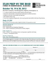
Steel — The Rolling Mill<br />
The greatest tonnage of steel ingots goes next to the rolling<br />
mill (See Figure 1) in which a white-hot ingot is passed<br />
between rolls having appropriately shaped circumferencial<br />
grooves. The ingot is thus elongated and reduced in crosssection.<br />
Figure 1 — Rolling Mill<br />
Generally ingots are “broken down” into blooms, slabs<br />
or billets in the “blooming mill,” etc. (These industry terms<br />
identify the shape and size ranges of the products of the<br />
initial rolling operations.) The blooms, slabs and billets go<br />
on to smaller mills for rolling into various finished shapes.<br />
Larger shapes may be rolled directly from ingots.<br />
A sequence of many different roll passes is required to<br />
reduce an 18” square by 6’ long ingot, for instance, to more<br />
than 3/8 of a mile of 2” by 2” by 1/4” angles.<br />
The “hot working” of the steel by rolling, squeezes and<br />
elongates the grains or crystals, making the steel somewhat<br />
fibrous in structure, with considerably increased longitudinal<br />
strength and toughness. (Steel should not be thought of,<br />
however, as actually having fibers.) Flat rolled products, that<br />
is, sheets and wide plates, generally are cross-rolled early in<br />
the rolling sequence, not only to gain width but also so that<br />
the improvement in properties will not be limited to the<br />
longitudinal direction.<br />
Steel destined for piano wire making is rolled on a rod<br />
mill to a diameter of slightly over 1/4". It comes off of the<br />
mill in a continuous coil instead of being straightened and<br />
cut to length on the hot bed.<br />
Up to this point in steel music-wire making, all of the<br />
processing has been at high temperatures, beginning in the<br />
molten state in the blast furnace and the steel furnace where<br />
the temperatures approach 3,000 degrees F. The forming<br />
work on the rolling mill in the solid state requires temperatures<br />
of the order of 2,000 degrees or more.<br />
Steel — Wire Drawing<br />
If the hot work of rolling added strength and toughness by<br />
elongating the grain structure, the cold work of the drawing<br />
process which follows in wire manufacture has an even<br />
greater effect on the properties of the steel.<br />
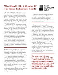
After cleaning and coating, the rolled steel is drawn cold<br />
through a fixed hole, or die (See Figure 2), which results in<br />
elongation together with reduction of cross-section, and a<br />
great increase in hardness, tensile strength and yield strength.<br />
(This will be discussed in “Testing & Properties.”) As used<br />
here, “cold” does not necessarily mean cold to the touch.<br />
Work at any temperature below the recrystallization tem-<br />
perature (several hundred degrees) is “cold work.”<br />
Continued on Next Page<br />
Figure 2 — Wire Drawing<br />
November 2000 / <strong>Piano</strong> <strong>Technicians</strong> Journal 19
Iron, Steel & <strong>Piano</strong>s<br />
Continued from Previous Page<br />
A corollary result of the increase in<br />
hardness is a reduction in ductility; that is,<br />
some of the ductility is “used up.” The<br />
fairly high carbon content of music wire<br />
steel limits its ductility to a reduction in<br />
area of about 30 percent or less per draft.<br />
Obviously many drafts are required to<br />
reduce a 1/4” rod to the diameter of music<br />
wire and the ductility must be restored<br />
between drafts. This is done by patent<br />
annealing, which consists of reheating the<br />
wire to a selected temperature, perhaps<br />
1,500 degrees F., followed by slow cooling<br />
in air or in a medium maintained at a<br />
rather high temperature. The result is<br />
recrystallization into a ductile grain<br />
structure. The cycle of drawing and<br />
patenting must be repeated several times.<br />
The wire is finished on the final draft, with<br />
no further heat treatment, so its strength<br />
and hardness depends a great deal on the<br />
amount of reduction after the last anneal.<br />
The traction for pulling the wire<br />
through the die is supplied through the reel, or block, on<br />
which it is wound. Since the tension is quite high, the wire,<br />
which comes through the die straight, is strained or cold<br />
worked to the curvature of the block’s circumference. A<br />
technician struggling to untangle a small coil of recoiled<br />
piano wire that “got away” can readily estimate the diameter<br />
of the draw block, unless, of course, the wire was straightened<br />
before recoiling.<br />
At this point let us leave the solid-state processing of<br />
steel, and look at the constitution and micro-structure of the<br />
various iron-carbon mixtures.<br />
The Iron-Iron Carbide System<br />
The molten metal which comes from the cupola or the steel<br />
furnace is largely a solution of iron carbide in iron, or more<br />
properly, a mutual solution of the two in each other. As<br />
cooling proceeds, the metal undergoes a series of changes<br />
(reversible on reheating), of which freezing is merely the<br />
first. The nature of these changes, and the temperatures at<br />
which they occur, depend largely on the percentage of<br />
carbon in the metal.<br />
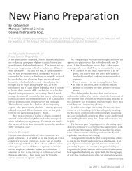
Figure 3, which is a simple version of the Iron-Iron<br />
Carbide Equilibrium Diagram, will help to visualize the<br />
state of different iron-carbon mixtures at various temperatures,<br />
and some of the changes that occur during solidification<br />
and cooling.<br />
20 <strong>Piano</strong> <strong>Technicians</strong> Journal / November 2000<br />
Figure 3 – Iron-Iron Carbide Equilibrium diagram<br />
The horizontal scale represents the percentage of<br />
carbon by weight, and covers the range from pure iron (0<br />
percent carbon) to pure iron carbide (6.67 percent carbon).<br />
The vertical scale represents the temperature in degrees<br />
Fahrenheit. We will not concern ourselves with the intricacies<br />
in the extremely low carbon area at the left side of the<br />
diagram.<br />
The lightly cross-hatched area of Figure 3 represents a<br />
“mushy,” partly frozen state, bounded at the top by the line<br />
marked “liquidus” and at the bottom by the line marked<br />
“solidus.” Above the liquidus the material is completely<br />
molten. Below the solidus it is completely frozen or solidified.<br />
The mushy, partly frozen state between has an analogy<br />
in salt-water solutions, which are mushy through a considerable<br />
temperature range between the freezing point of pure<br />
water and the rather lower total freezing point of the<br />
solution. The reader will note that, for both pure iron and<br />
the eutectic cast iron (4.3 percent carbon) the liquidus and<br />
the solidus coincide — there is no mushy state, whereas at 2<br />
percent carbon the mushy state persists through a range of<br />
about 450 Farenheit degrees.<br />
Below the solidus, solid state changes occur during<br />
cooling, which, to simplify, consist of the separation of iron,<br />
carbon, and iron carbide in various forms as their mutual<br />
solubility changes with falling temperature. These separations<br />
are, of course, microscopic and result in changes in<br />
crystalline structure. Volumes could be written analyzing
these changes and their practical significance. We will limit<br />
ourselves to a few observations relevant to this article.<br />
To better understand Figure 3, one must realize that in<br />
the solid state iron exists (at different temperatures) in at<br />
least two allotropic forms. Below 1,333 degrees F. it is stable<br />
as alpha iron. Above 1,333 degrees it is stable as gamma iron.<br />
These forms have different crystalline structures and their<br />
interest to us is in the fact that the solubility of carbon in gamma<br />
iron is fairly high, but in alpha iron it is extremely low.<br />
With these facts before us we are ready for definitions<br />
of some of the terms appearing in Figure 3.<br />
Austenite: A solid solution of carbon in gamma iron.<br />
The maximum carbon in austenite varies<br />
between 2 percent at 2,065 degrees F. and<br />
0.8 percent at 1,333 degrees F. (See A cm<br />
line.) Austenite does not exist below 1,333<br />
degrees F. because gamma iron changes to<br />
alpha below that temperature.<br />
Ferrite: Almost carbon-less alpha iron. (Limited to<br />
about 0.02 percent carbon, as carbon is<br />
virtually insoluble in alpha iron.)<br />
Cementite: Iron carbide (Fe 3 C). An extremely hard and<br />
brittle compound, hard enough to scratch<br />
glass. Contains 6.67 percent carbon by<br />
weight.<br />
Pearlite: A low-temperature (below 1,333 degrees<br />
F.), rather homogenous laminar mixture of<br />
ferrite and cementite, containing about 0.8<br />
percent carbon.<br />
Now, referring to Figure 3, let us follow a few ironcarbon<br />
materials from the molten to the cold state.<br />
Suppose we have molten steel of 0.8 percent carbon,<br />
which is permitted to cool slowly. Freezing commences at<br />
about 2,690 degrees F. and is complete at about 2,520<br />
degrees. The solid austenite then cools without change right<br />
down to the 1,333-degree line. At this point the gamma<br />
iron changes to alpha iron and the austenite transforms to<br />
pearlite as the carbon is cast out of solution in iron carbide<br />
laminae. This all-pearlite 0.8 percent carbon steel is said to<br />
have eutectoid composition.<br />
Pearlite actually retains its identity in non-eutectoid<br />
steels, but since its carbon content is uniform at 0.8 percent,<br />
these non-eutectoid steels are necessarily not pure pearlite.<br />
If the steel is hypo-eutectoid (less than 0.8 percent carbon)<br />
it consists of pearlite and ferrite grains mixed. If the steel is<br />
hypereutectoid (more than 0.8 percent carbon) it consists of<br />
pearlite and cementite grains mixed.<br />
The precipitated cementite in hyper-eutectoid steel<br />
forms at the pearlite grain boundaries, and this network of<br />
cementite increases the hardness and strength of the steel,<br />
compared with that of steel which is lower in carbon.<br />
It might be of interest to trace the cooling cycle of a<br />
hyper-eutectoid steel of, say 1.25 percent carbon. This steel<br />
starts to freeze at about 2,650 degrees F. and freezing is<br />
complete at about 2,350 degrees. It now remains solid<br />
austenite containing 1.25 percent carbon until it cools to<br />
the A cm line at about 1,675 degrees. At this point the solution<br />
is saturated with carbon and the excess carbon starts to<br />
precipitate in cementite. This precipitation of cementite<br />
continues on down to 1,333 degrees, at which point the<br />
remaining austenite, which has now reached eutectoid<br />
composition, transforms to pearlite, and we have a mixture<br />
of pearlite and Cementite grains as mentioned in the<br />
preceding two paragraphs, and a rather hard steel.<br />
Hypo-eutectoid steel (less than 0.8 percent carbon),<br />
after freezing, continues to cool as austenite down to the A 1<br />
line, at which point it begins to cast out ferrite crystals. This<br />
continues on down to 1,333 degrees F. at which point again<br />
the remaining austenite has reached eutectoid composition,<br />
and transforms to pearlite, resulting in pearlite grains in a<br />
ferrite matrix. Ferrite is similar in properties to pure iron.<br />
Hence steels low in carbon are relatively soft and of lower<br />
tensile strength than the high carbon steels.<br />
The temperature-related changes we have been discussing<br />
are also time-related. The equilibrium states represented<br />
by the various areas of Figure 3 assume that the cooling<br />
metal has the necessary “leisure” for the changes to take<br />
place. Sudden cooling may force non-equilibrium changes<br />
that alter the crystalline structure and the properties of the<br />
material.<br />
These facts are the basis of the heat treatment of steel,<br />
which consists of slowing or speeding the cooling rate<br />
through critical temperature ranges to facilitate or inhibit<br />
change. Thus, in the wire-drawing process, ductility was<br />
restored between drafts by reheating the wire above the A 3 -<br />
A cm lines to the all-austenite condition, then cooling it<br />
slowly to below the A 1 line. A rapid quench cooling on the<br />
other hand would have increased the hardness and reduced<br />
the ductility by forcing a non-equilibrium change into one<br />
of the harder forms, as, for instance, Martensite (not defined<br />
in this article).<br />
Steel for piano wire, having about 0.85 to 0.90 percent<br />
carbon, is near eutectoid composition and hence mostly<br />
pearlite. It affords an excellent compromise between high<br />
tensile strength and high ductility.<br />
Now let us look at the cast iron area of Figure 3. We see<br />
at once that a cast iron of 4.3 percent carbon has the<br />
minimum freezing point of all the iron-carbon mixtures<br />
Continued on Next Page<br />
November 2000 / <strong>Piano</strong> <strong>Technicians</strong> Journal 21
(2,065 degrees F.). We see also that it has no mushy stage,<br />
since the liquidus and solidus lines coincide at that carbon<br />
ratio. In foundry work this material would have the obvious<br />
advantage of remaining fully fluid at a relatively low temperature,<br />
flowing freely in intricate molds such as those<br />
required for piano plates. Also, with almost no temperature<br />
change during freezing, shrinkage during freezing would be<br />
minimal, resulting in sound castings free of shrinkage<br />
defects. While the carbon in gray cast iron rarely exceeds 3.5<br />
percent, the advantages named above are still partly retained<br />
at this percentage.<br />
In view of what we have said about the hardness of<br />
mixtures high in carbon (cementite), a 3.5 percent carbon<br />
cast iron might seem much too hard and brittle to be useful.<br />
Indeed it would be if all the carbon remained in combination<br />
as cementite. But the silicon present in the metal comes<br />
to the rescue. As freezing and subsequent cooling progresses,<br />
most of the carbon in excess of the eutectoid ratio (0.8<br />
A plea for advice about a distressing occurrence<br />
comes from New York State:<br />
“As a former member, retired, I am seeking some<br />
information. I pulled up an old piano 1/2 note to 440<br />
pitch, informing the man it was risky to raise the pitch. In<br />
doing so, after the pull-up, the plate [cracked] in the treble<br />
section.<br />
What I want to know is, who is responsible?<br />
This is the first time this has happened to me in 58<br />
years tuning.”<br />
Some [technicians] tune pianos for a lifetime<br />
without ever experiencing a broken plate. But it does<br />
occur once in a while. It is always sudden and unpredictable,<br />
the result of some unseen internal strain in<br />
the plate. It may be the result of metal fatigue in a<br />
plate that was never quite perfectly fitted to the heavy<br />
wooden frame of the piano, but was forced to conform<br />
to it by the many bolts and screws. It may be the<br />
result of slight and gradual changes in the wooden<br />
frame itself, to which the cast-iron plate is not able to<br />
accommodate itself. It may be the result of a hidden<br />
weakness in the casting, which finally “lets go.” It is, as<br />
I say, a rare thing, but it does occur. It has been known<br />
to occur when the piano was sitting idle by itself,<br />
22 <strong>Piano</strong> <strong>Technicians</strong> Journal / November 2000<br />
percent) is precipitated as graphite flakes, interspersed with<br />
the ferrite and cementite crystals, so that little cement-ite is<br />
present except in pearlite form. This formation of graphite<br />
is essential to the character of gray cast iron, and the silicon<br />
is the chief agent in its formation. Hence the great importance<br />
of silicon in gray cast iron. (Figure 3 does not try to<br />
show this effect.)<br />
Testing & Properties<br />
Since the properties of a material determine its suitability<br />
for a particular purpose, the testing of these properties is<br />
very important.<br />
Some vital properties of engineering materials are<br />
toughness, hardness, and fatigue strength. Toughness is<br />
measured by the energy absorbed before fracture in a<br />
standardized impact test. Hardness is measured by the<br />
penetration of a standardized indenting die. Fatigue strength<br />
is measured as the maximum stress tolerable under indefi-<br />
Broken Plate! Who Is Responsible?<br />
with no tuner within miles!<br />
It is safe to assert that a “healthy” plate, properly<br />
designed, properly fitted and secured in the piano,<br />
will not break under the ordinary stresses of the<br />
tuning process, even when the string tension is being<br />
raised back to standard after long neglect. It is designed<br />
to stand much higher stresses than those set up<br />
by strings tuned to standard pitch.<br />
There is even some question whether such a<br />
plate could be broken by deliberately over pulling the<br />
strings or whether the strings would not break first.<br />
But since the tuner does not do this, the question is<br />
academic.<br />
So there is no basis for considering the tuner to<br />
be responsible for plate breakage that occurs during<br />
or after tuning. This fact is easier for customers to<br />
accept if they are forewarned that there is risk involved<br />
in raising the pitch of a piano. That this risk is<br />
extremely small is shown by the fact that our inquirer<br />
tuned for 58 years, including, I am sure, hundreds of<br />
pitch raises as drastic as this one, without ever experiencing<br />
a broken plate.<br />
— Don Galt
nitely repeated cyclic loads.<br />
The properties of steel most important to us in connection<br />
with piano wire are those called tensile properties.<br />
Because there are some striking similarities between wire<br />
drawing and the tensile testing of steel, we will examine the<br />
latter in some detail.<br />
The tensile test consists of stretching a specimen of<br />
known cross sectional area to failure in a testing machine.<br />
The maximum tensile stress endured by the specimen<br />
before failure, divided by the original cross-sectional area,<br />
gives the ultimate tensile strength per unit of area, usually<br />
called simply the tensile strength. In countries using the<br />
English system, the tensile strength and the other tensile<br />
properties, such as elastic limit and yield strength, are given<br />
in pounds per square inch. It is usual to use a specimen<br />
accurately machined to a diameter of 0.505". This has a<br />
cross-section of 0.2 square inch, which is a convenient<br />
divisor for converting the measured load on the specimen<br />
into the stress per square inch.<br />
While the tensile strength is easily determined with<br />
proper equipment, it is not the most important tensile<br />
property of steel. More important is the amount of stress it can<br />
stand without permanent deformation. The specimen elongates<br />
as it undergoes constantly increasing loads in the testing<br />
machine. At first this elongation is elastic; that is, if the<br />
tension is removed the original length will be recovered. As<br />
the load is further increased an elastic limit is reached, and<br />
plastic, or permanent deformation begins. The precise elastic<br />
limit is seldom determined in practice, as the process is<br />
cumbersome. It requires the alternate application and release<br />
of increasing loads, with measurement of the gauge length<br />
each time to determine if the behavior is still elastic.<br />
The tensile property usually obtained instead of the<br />
elastic limit is the yield point, which, in steel, is only slightly<br />
above the elastic limit. This is the unit tensile stress at which<br />
the specimen continues to elongate for a period without<br />
any increase in load. The term “yield” is quite descriptive of<br />
what takes place. At and above the yield point permanent<br />
slips occur along planes in the crystals, until they are arrested<br />
by crystal boundaries and broken grains. At first, yielding is<br />
distributed throughout the length of the specimen, but as<br />
the load rises a “neck” starts to develop in the specimen and<br />
further elongation is concentrated at this neck. After<br />
necking starts, elongation continues under decreasing loads,<br />
because the effective cross-section is decreasing, and this<br />
continues until fracture occurs at the neck.<br />
The cold work of stretching actually hardens and<br />
strengthens the stretched steel, so that the true unit stress on the<br />
material at fracture (the load divided by the instantaneous<br />
cross-section of the neck) is considerably greater than the tensile<br />
strength (the maximum load achieved, divided by the<br />
original cross-section). If one thinks of wire drawing as a<br />
sort of controlled tensile test, in which a “continuous neck”<br />
of uniform cross-section is formed, it is not hard to see how<br />
the drawn wire develops strength and hardness superior to<br />
those of the hot rolled rod from which it is drawn. The<br />
drawn wire exhibits a new elastic limit and yield point,<br />
higher than those of the steel in as-rolled condition, and is<br />
capable of elastic behavior within these limits.<br />
It is imperative that the cold work of drawing not be<br />
overdone, lest the wire become too brittle.<br />
(The tensile test and the drawing process are not perfectly<br />
analogous. In drawing, the lateral compression of the metal by the<br />
die is an effect similar to cold forging—an effect absent from the<br />
tensile test.)<br />
What we have discussed is the testing of rolled steel.<br />
Wire can be tested similarly, though it is customary to quote<br />
the breaking strength of wire rather than the tensile<br />
strength. Tensile strength is a property of the material<br />
independent of size, whereas breaking strength is a property<br />
of the specimen, depending on both tensile strength and<br />
sectional area.<br />
Generally, smaller sizes of piano wire have higher tensile<br />
properties than larger sizes because of the additional drafting<br />
or cold work. Also, wire used for bass string cores generally<br />
is made with lower properties, in order to preserve enough<br />
malleability so that the wire can be swedged, or flattened at<br />
the start and finish of the winding. Moreover, some manufacturers<br />
make more than one grade of wire, for example,<br />
two grades of bass and two grades of treble wire. For the<br />
most part these different grades and sizes come from the<br />
same steel and owe the difference in their properties to the<br />
amount of drafting and the spacing of annealings in the<br />
manufacturing sequence.<br />
The yield strength of the wire, which cannot be exceeded<br />
in piano stringing and tuning without serious<br />
damage, is determined by a rather arbitrary process known<br />
as the 0.2 percent offset method. It is generally found to be<br />
about 70 percent of the breaking strength. I do not mean to<br />
pass lightly over the elastic limit and yield strength. The<br />
non-determination of elastic limit, and the use of an<br />
arbitrary method for yield strength, are dictated by practical<br />
considerations, not by any lack of importance of these<br />
properties. Long and careful practice has shown that this<br />
testing method for yield strength gives a valid measure of<br />
the two properties in piano wire.<br />
In common with many other materials, steel under high<br />
Continued on Next Page<br />
November 2000 / <strong>Piano</strong> <strong>Technicians</strong> Journal 23
Iron, Steel & <strong>Piano</strong>s<br />
Continued from Previous Page<br />
tensile stress continues to elongate slightly for an indefinite<br />
time. This elongation is called creep. In most steel uses creep<br />
is considered negligible if the temperature is less than 40<br />
percent of the melting point on the absolute scale, i.e., less<br />
than about 700 degrees F. With piano strings, whose pitch is<br />
so sensitive to a very small change in tension, creep at<br />
ordinary temperatures is probably a factor in both the quick<br />
loss of pitch in newly strung pianos (so-called primary<br />
creep), and in the long-term loss of<br />
pitch (secondary creep).<br />
Fatigue in metal has been mentioned<br />
briefly, fatigue strength being the<br />
tolerance of indefinitely repeated cyclic<br />
loads. The high frequency reverse<br />
bending that occurs constantly in a<br />
highly tensioned vibrating string,<br />
particularly at the ends where the<br />
transverse waves are reflected, is surely<br />
high stress cyclic loading, and many<br />
string breaks in playing must be regarded<br />
as fatigue failures.<br />
Whenever a string is placed in a<br />
piano, it is necessarily cold worked at<br />
several points, such as the bridge pins,<br />
the agraffe, etc. Every non-elastic bend<br />
that is put into the wire tends to harden<br />
the wire by effectively cold working the<br />
steel at that point. The fibers on the<br />
convex side of any plastic bend have<br />
probably been stretched beyond the<br />
yield strength. This point will then be<br />
slightly more brittle than other parts of<br />
the string, and a likely candidate for<br />
ultimate fracture. One such point is the<br />
agraffe. Another is the point of tangency<br />
where the string starts to wind around<br />
the tuning pin. Repeated small tuning<br />
changes subject a short section of the<br />
string to alternate bending and straightening,<br />
which, even though slight, tend<br />
to work-harden the steel. This is<br />
probably why so many “old age” string<br />
breaks occur at the tuning pin.<br />
It should be obvious that piano<br />
strings are hard-working elements of<br />
the musical structure of the piano and<br />
we should be careful not to do anything<br />
to make their lot harder. Specifically, we<br />
should avoid subjecting them to<br />
unnecessary plastic bends by kinking or<br />
24 <strong>Piano</strong> <strong>Technicians</strong> Journal / November 2000<br />
any other means, and to excessively high tension. Remember<br />
that any tension approaching 70 percent of the breaking strength is<br />
dangerously close to the yield strength.<br />
A few more words are in order about the properties of<br />
gray cast iron, which is a more prosaic cousin of piano wire.<br />
Its eminent suitability from the standpoint of manufacturing<br />
convenience in piano plate work has been mentioned.<br />
Its low freezing point (compared with other iron-carbon
material), and the proximity to each other of its liquidus and<br />
solidus temperatures combine to make for sound, uniform<br />
castings.<br />
Gray cast iron also has about the same coefficient of<br />
thermal expansion as steel music wire, which is a factor<br />
favoring tuning stability. Lighter metals sometimes used for<br />
piano plates have somewhat higher coefficients of thermal<br />
expansion.<br />
Gray cast iron has good machinability, as anyone who has<br />
drilled a piano plate has observed. This characteristic is<br />
enhanced by the presence of the carbon in graphite flake<br />
form.<br />
Gray cast iron has low tensile and compressive strength<br />
compared with steel, its ultimate tensile strength being about<br />
25,000/30,000 pounds per square inch. Structural steel has a<br />
tensile strength about three times as high, and cold drawn<br />
piano wire about ten times as high. In piano plates this relative<br />
low strength is not a particular disadvantage. The plate needs<br />
to be heavy enough to afford a solid platform for the strings<br />
to stand on while they are shaking the soundboard. Furthermore,<br />
the parts of the plate must be large enough so that there<br />
will be little deflection under load. These two requirements<br />
WIRE DRAWING A.D. 1540<br />
Pure Sound<br />
Top quality Stainless<br />
Steel <strong>Piano</strong> Wire<br />
from 1600 N/mm 2 - mid 19th century<br />
to 2200 N/mm 2 - modern pianos (short scaling)<br />
Most versatile high tech piano wire based on latest<br />
developments in stainless steel processing.<br />
Tuning stability better than average.<br />
Lower inharmonicity. Lovely sound!<br />
Prices in Euros: approx. 95¢ to the Euro at June 2000<br />
500 g - 15.00 250 g - 8.50 - 125 g - 5.50 (0.700 mm - 1.50 mm)<br />
500 g - 21.00 250 g - 11.00 - 125 g - 7.00 (0.500 mm - 0.675 mm)<br />
Complete list of breaking strengths, yield points<br />
and other data available.<br />
Pure Sound<br />
Juan & Mary Más Cabré<br />
Eline Verestraat 46 • 1183 KZ AMSTELVEEN, Netherland<br />
Phone: +31.20.6418099 Fax: +31.20.6407621<br />
E-mail: info@puresound-wire.com<br />
permit use of a material of relatively low unit strength.<br />
One of the properties of gray cast iron, which makes it<br />
particularly suitable for machinery bases, is also to its advantage<br />
in piano plates. This is its tendency toward internal selfdamping<br />
of vibrations. This property, largely due to the<br />
honeycombing with graphite carbon, means that plates of<br />
gray cast iron are not apt to show objectionable resonance.<br />
They do not “ring.” Happily, the words “bell metal,” which we<br />
all have seen cast into some piano plates, are simply not true.<br />
The graphite carbon of gray cast iron makes it very<br />
difficult to weld. Many piano technicians have had successful<br />
experiences in repairing broken plates by welding. It must be<br />
said, however, that the weldability of gray cast iron is poor, and<br />
that these successful repairs are in spite of, not because of, the<br />
properties of the metal. After welding, the homogeneity of the<br />
casting is gone, and there is sure to be a zone of weakness<br />
somewhere. Fortunately the plate is usually over-designed as<br />
far as structural strength is concerned and the weakness of the<br />
weld repair is not necessarily fatal. Sometimes there is no<br />
alternative to attempting repair by welding and it is not the<br />
author’s intent to write against it. But due to the microstructure<br />
of the material, welding cannot be thought of as a<br />
reliable means of making broken gray<br />
cast iron “as good as new.”<br />
Of course, there are other iron<br />
materials to be found in pianos in<br />
smaller quantities. Tuning pins are made<br />
of cold-drawn steel wire, not so hard,<br />
considerably larger in diameter than<br />
piano wire. The many steel screws are<br />
made of steel that is made brittle by the<br />
presence of sulphur, so that it will thread<br />
easily and cleanly. The leg plates of<br />
grand pianos are made of a tougher cast<br />
iron than the gray cast iron of the string<br />
plates. They are lower in carbon, much<br />
lower in silicon and higher in manganese,<br />
and their carbon is not in graphite<br />
flake form. They exhibit a fair degree of<br />
malleability and less likelihood of<br />
fracture under shock than gray cast iron.<br />
But these two cousins in the iron<br />
family, steel music wire and gray cast<br />
iron plates, are the real backbone of the<br />
modern piano. Without them it would<br />
be, as it once was, a very different<br />
instrument.<br />
November 2000 / <strong>Piano</strong> <strong>Technicians</strong> Journal 25
<strong>Piano</strong> Plate Breakage: A Case Stud<br />
By Steve Brady, RPT<br />
Journal Editor<br />
The story I relate here is about an event, or series<br />
of events, in the life of Marnie Squire, an<br />
Associate member of the Cincinnati, OH,<br />
chapter of PTG. She has been kind enough to<br />
provide the documentation from her case for use in this<br />
issue of the Journal. “If it can help save someone else from<br />
the kind of nightmare I went through,” she says, “I’m happy<br />
to share my story.”<br />
At about 10:30 a.m. on Friday, July 2, 1993, Marnie<br />
Squire arrived to tune a small Fischer grand piano at a home<br />
in Middletown, OH. The piano, an Aeolian product, had not<br />
been tuned in 13 years. Squire played the piano briefly to<br />
evaluate its condition and found several keys not playing as<br />
well as some damper problems. The piano was 37 cents flat.<br />
After bringing the piano back to a condition of rough<br />
playability, Squire began the process of raising pitch. Using a<br />
Sanderson Accu-Tuner, she completed a “normal” first pass<br />
and had nearly completed a second pass. Then, “I was about to<br />
tune the second or third string from the bottom of the bass<br />
section. I played the keys and a huge ‘bang!’ happened. I had<br />
no idea what had happened and was very shaken.” Looking<br />
over the piano she saw a crack in the second plate strut from<br />
the top and another crack in the tuning pin area at the bass/<br />
tenor break. Mortified, she called the owner of the piano, who<br />
was at work and explained what had happened.<br />
The piano owner filed a lawsuit over the broken plate.<br />
The owner enlisted the aid of another piano technician in the<br />
area as an “expert” witness and this technician (whose name is<br />
omitted here) told the piano owner that Squire had brought<br />
the pitch up too fast, that she didn’t know what she was doing,<br />
and that she had actually broken the plate!<br />
In September of 1993, Marnie Squire retained an attorney<br />
to defend herself in the lawsuit and the long process of<br />
gathering evidence began. Several PTG members sprang to<br />
Squire’s aid by examining the piano and writing opinions,<br />
some even performing sophisticated analyses based on the<br />
physical evidence. From over two dozen written opinions<br />
placed at my disposal by Marnie Squire, I have excerpted a<br />
number of relevant quotations.<br />
Willard Sims, piano service manager at Baldwin from 1946 to<br />
1984, wrote on September 17, 1993:<br />
“The tuning of a piano by an experienced technician<br />
will not cause the string plate to fail.” In another letter dated<br />
April 10, 1994, Sims reiterated this stance: “I repeat my statement<br />
that the tuning of a piano will not cause plate failure. If<br />
a rebuilder refurbished and perhaps rescaled the piano, re-<br />
26 <strong>Piano</strong> <strong>Technicians</strong> Journal / November 2000<br />
moving and resetting the plate, then that action may result in<br />
plate failure.”<br />
Sandy West, a later piano service manager for Baldwin, elaborated:<br />
“It is my considered opinion that a broken plate cannot<br />
be blamed or attributed to a typical tuning/service call. My<br />
experience is that strings will break before the plate will. A<br />
broken plate is usually the result of some major trauma, such<br />
as the piano being dropped or the result of a defect in the<br />
manufacture of the plate. In both such instances the actual<br />
crack or break may not show up for quite some time. It will<br />
develop over time as an eventual result of the continued pressure<br />
on the fault by all the strings. Simply tuning the piano<br />
would not cause such damage.”<br />
Dr. Albert Sanderson pointed out that Marnie Squire’s pitchraising<br />
method had been entirely appropriate, then added:<br />
“It has been my observation that plates that break under<br />
normal tuning stress have a flaw in the casting that can be<br />
seen when the break is examined. A flaw could be a bubble<br />
in the casting or a crack that has been growing gradually over<br />
the years owing to metal fatigue.”<br />
Noted piano rebuilder Tony Geers reiterated the now-familiar<br />
theme:<br />
“Based on the information we have at hand, most notably<br />
the fact that the piano plate broke in both the tuning pin<br />
area and treble bar, it would be our conclusion that faulty<br />
installation of the plate during the manufacturing process is<br />
the most likely cause for the breakage. It is impossible for a<br />
tuner to break a plate by tuning alone. There must be other<br />
circumstances present, i.e., faulty manufacturing, flaw in the<br />
cast iron, piano dropped, etc. Tuning works against the strength<br />
of the cast-iron plate. Over-tuning would cause string breakage<br />
long before any possible damage to the plate could occur.<br />
“If the plate was improperly installed at the factory, plate<br />
breakage is a very real possibility. Improper installation could<br />
be the bending of the plate over the pinblock or securing<br />
bolts or screws. When tension is added by tuning, extreme<br />
stress is focused on the bent portion of the plate; such as in<br />
the area of the tuning pins and treble bars.”<br />
A letter from prominent piano technician and educator Jim<br />
Geiger stated:<br />
“The conclusion is that a normal piano plate, designed<br />
to withstand 40 tons of pressure would not be broken by the<br />
tension from the piano strings regardless of the applied tension,<br />
how fast the tension is applied and at what point of the
ase Study<br />
scale the tension is applied. In the piano factories the tension<br />
is applied as fast as the tuner can bring the strings up to pitch.<br />
Indeed, it should not be possible to break a normal piano<br />
plate with string tension alone, because the strings would<br />
break first. There is just not enough margin between the actual<br />
string tension and the tension at which failure will occur<br />
for the piano wire to be able to produce the force necessary<br />
to cause a good piano plate to fracture.”<br />
University technician Rolf von Walthausen added some background<br />
on the material, then pointed out that some piano models<br />
frequently suffer cracked plates. In this particular case, it turned out<br />
that many Aeolian grands had suffered the same fate. von Walthausen<br />
wrote:<br />
“<strong>Piano</strong> plates are made of cast iron, which is a material<br />
that is extremely hard, but also brittle. Properly cast and installed,<br />
it is capable of withstanding tremendous pressure from<br />
the strings, which are fastened to and held in tension by the<br />
plate. Improperly cast or installed, a cast-iron plate could easily<br />
break or crack. Even if piano wire, which is a steel alloy<br />
with great tensile strength, is stretched quickly beyond a certain<br />
stiffness, the wire will break far, far before exerting a<br />
force on the piano plate that would cause breakage or any<br />
type of damage to the plate.<br />
“Some brands of pianos have frequent occurrence of plate<br />
breakage or cracking. It is rare to find an old Bechstein grand<br />
piano, for example, without a crack in the plate. Opinions<br />
from experts differ as to why this is so (poor casting, design or<br />
installation), but one thing is never disputed: tuning or pitch<br />
raising was never the cause.”<br />
Nevin Essex, another highly regarded technician from the<br />
Cincinnati area, wrote:<br />
“I have been teaching piano tuning and technology<br />
through the <strong>Guild</strong>, at universities and on my own since 1982.<br />
I have researched teaching methods and developed my own.<br />
Nowhere have I ever seen or heard any scientific evidence<br />
that suggests that a piano tuner can break a plate. My understanding<br />
is that plates are designed to withstand much more<br />
tension than exists in any piano. I have never heard any credible<br />
account of a piano tuner breaking a plate. I was never<br />
taught nor do I teach any technique or method designed to<br />
prevent a plate from breaking while tuning. Tuning methods<br />
that emphasize raising pitch evenly do so for the purpose of<br />
achieving a good tuning, not for preventing the plate from<br />
breaking.<br />
The author of The <strong>Piano</strong> Book, Larry Fine, weighed in with<br />
an opinion that even contributed a touch of humor to the situation:<br />
“There are only two ways I know of that a tuner can<br />
break a piano plate that is not defective while servicing a<br />
piano in the home. One way is to excessively tighten the<br />
nose bolt that supports the plate in the center area of the<br />
piano. This is an adjustment not normally made outside of a<br />
piano rebuilding shop. The other way is to take a sledge hammer<br />
to it. In other words, it is virtually impossible for a piano<br />
tuner to break a plate during the normal tuning and pitchraising<br />
of a piano unless the plate is already defective and<br />
ready to break, in which case any tuner, regardless of skill or<br />
method of tuning, will be the unwitting agent of such breakage<br />
by fate alone. Even in a worst-case scenario, in which a<br />
tuner sought to sabotage a piano by stretching all the strings<br />
far above standard pitch, chances are that the strings would<br />
break long before the plate would. Tuners are sometimes<br />
blamed for plate breakage by understandably distraught piano<br />
owners, but in every such case the blame is misguided<br />
and completely unjustified.”<br />
In expectation that the lawsuit would come to trial,<br />
Marnie Squire asked Jim Ellis to look at the piano and to<br />
render an opinion from his background as an engineer. After<br />
examining the piano, Ellis wrote a formal analysis (included in<br />
this issue of PTJ) proving that the plate was poorly designed.<br />
“What I couldn’t understand,” he said, “is why the plate hadn’t<br />
broken when the piano was first strung in the factory.”<br />
Enter Paul Monachino, who had worked for the now-defunct<br />
Aeolian Corporation during the years when the subject piano was<br />
manufactured. Delivering the death-blow to the plaintiff’’s case,<br />
Monachino wrote:<br />
“This problem is nothing new in this style piano. I have<br />
seen this particular plate cracked in the same place many, many<br />
times. The fault lies in the construction of the plate and not in<br />
the tuning of the piano.” (Monachino’s emphases —SB)<br />
The night before the case was scheduled for trial, the<br />
piano owner’s “expert” witness backed out, leaving the<br />
prosecution with no case at all. The shame of the whole story<br />
is that Marnie Squire had been placed in such a position to<br />
begin with. Besides having to spend hundreds of dollars in<br />
attorney’s fees, she was “a nervous wreck” for the year that<br />
passed before resolution. The silver lining to this cloud is that,<br />
because of what she went through, and the unanimous<br />
opinions provided by the real experts, this kind of nightmare<br />
— a lawsuit obviously without basis in fact — should not<br />
have to be suffered by any piano technician again.<br />
November 2000 / <strong>Piano</strong> <strong>Technicians</strong> Journal 27
An Analysis of a Broken Plate<br />
By Jim Ellis, RPT<br />
Knoxville, TN Chapter<br />
Background<br />
When Steve Brady called and asked me if I would<br />
contribute an article about broken piano plates<br />
(to replace an article promised by someone else,<br />
but which had never actually materialized), his deadline was<br />
just five days away and I was leaving on a trip in three days.<br />
When I returned it would be too late. Because of the time<br />
constraint Steve and I decided that I should just use an<br />
analysis that I did back in May, 1994 for the Journal article.<br />
The piano was a 1973 J&C Fischer that had been<br />
neglected for several years and allowed to go 37 cents flat.<br />
The scale design had only three major divisions, no agraffes,<br />
and the forward termination for the strings was a long<br />
curved capo bar that ran all the way from #1 in the bass to<br />
#88 in the treble. The middle section spanned 32 triplestring<br />
unisons without any additional support and the<br />
bearing angle of the strings against the bar was excessive.<br />
The dimensional cross section of the bar was minimal, and<br />
there were no shoulder (nose) bolts to secure the plate struts<br />
to any beams underneath. Immediately after the tunertechnician<br />
brought the piano up to standard pitch and<br />
began to check the tuning, the middle section of the capo<br />
bar broke.<br />
Another technician claimed that the plate broke<br />
because the tuner brought the piano back up to standard<br />
pitch in one tuning rather than in several small increments<br />
spread out over a period of days, weeks or months. The<br />
owner filed a lawsuit against the tuner for an amount that, in<br />
my opinion, was far in excess of the actual worth of the<br />
piano. I was asked to be an “expert witness” for the tuner.<br />
Although the piano was located in the Cincinnati area some<br />
260 miles from where I live, I agreed to do it for net<br />
expenses only. The intentions of the piano owner may have<br />
been perfectly honest, but his/her decision to sue was based<br />
upon an erroneous conclusion by another technician and<br />
the result could have set a precedent that would have been<br />
absolutely wrong!<br />
After taking a good look at this particular piano I was<br />
28 <strong>Piano</strong> <strong>Technicians</strong> Journal / November 2000<br />
surprised that that section of the capo bar had not broken<br />
when the piano was first chipped at the factory. I was later<br />
told that some of them did.<br />
The following is the analysis that I presented to the<br />
tuner-technician’s attorney and I was well aware that I<br />
might be called upon to present it in court later on. Fortunately<br />
for everyone the suit was withdrawn the day before<br />
the hearing. This was such a no-winner! The design of the<br />
piano was, in my opinion, just asking for trouble.<br />
The original analysis included four figures, which are<br />
included here, and eight photographs — primarily for the<br />
education of the attorney — that do not appear here<br />
because they are no longer available.<br />
Tuning Procedure Used by Mrs. Squire<br />
Mrs. Squire and I discussed the procedure she had used to<br />
tune the piano just before the plate broke. The piano had<br />
been neglected and not tuned for more than a decade. Mrs.<br />
Squire measured its pitch and found it to be about 37 cents<br />
flat. In tonal nomenclature, a “cent” is 1/100 part of a<br />
semitone; a “semitone” is 1/12 part of an octave; and an<br />
octave represents a ratio of 2:1 in frequency, or pitch. In<br />
going up the musical scale, each of the 12 semitones in an<br />
octave increases by the 12th root of 2, or 1.059463094<br />
above the one below it. Therefore, being “37 cents flat”<br />
means that the frequency (pitch) of the notes on the piano<br />
was about 98 percent of what it should have been at standard<br />
pitch (A=440Hz).<br />
When a piano is flat (low in pitch) by this much,<br />
current procedure calls for raising the pitch of each string<br />
very, very slightly above its normal frequency so that when<br />
it settles after tuning it will be at, or very near, the desired<br />
pitch. It is well within the limits of good tuning practice to<br />
raise the pitch of a piano by 37 cents at one time. Obviously,<br />
the tuner then repeats the tuning in order to obtain a finer<br />
tuning, since the piano will always settle back some. This<br />
procedure is accepted and recommended throughout the
industry. It is my understanding that Mrs. Squire had<br />
actually finished the tuning, and was playing chords to<br />
evaluate the job, when the plate finally broke.<br />
Mrs. Squire was following a tuning procedure that was,<br />
and is, appropriate for the occasion. I can find no fault at all<br />
with what she did.<br />
The Actual Cause of the Plate’s Failure<br />
In order to describe clearly what happened, and what<br />
caused this plate to break in this piano, I must first outline<br />
the most basic principles of cast-iron plates in grand pianos.<br />
Basic Construction of a <strong>Piano</strong> Plate<br />
The plate of a piano is the structure that provides a very<br />
strong, rigid and stable framework inside which all the<br />
strings are strung. It is what makes the modern piano<br />
capable of staying in tune for weeks and months at a time.<br />
<strong>Piano</strong> plates are made of gray cast iron, and not “bell metal,”<br />
as some people believe.<br />
Cast iron is chosen because it is economical, mechanically<br />
stable and has a low coefficient of thermal expansion.<br />
It is very strong under compression, but weak under tension,<br />
Figure 1<br />
and brittle. Its properties depend upon the amount of<br />
carbon and other impurities that it contains, and these can<br />
vary widely. For these reasons, a quality grand piano is<br />
designed so that the areas of high stress concentration in the<br />
plate are those that are under compression, not tension. For<br />
maximum stability and strength, piano plates are almost<br />
always cast in one piece. They are usually finished with a<br />
bronze-lacquer-base paint.<br />
For purposes of illustration, Photo 1 is a photograph of<br />
the tuning-pin area of a high-quality grand piano, not the<br />
piano with the broken plate. [EDITOR’S NOTE: Remember<br />
none of the photos referenced in this article are available for<br />
publication. — SB] The photo shows the reinforcing bars<br />
that are a part of the plate structure, tuning pins, agraffes,<br />
capo bar and strings. The bars that run parallel to the strings<br />
and carry the load of the tension of all the strings lie mostly<br />
above the strings. The total tension can be anything from<br />
30,000 to 50,000 pounds, depending upon the size and<br />
scaling of the piano. Because the strings are all pulling<br />
inward on these bars in a plane that lies below their<br />
centerlines, the bars have a tendency to arch upward in the<br />
middle (See Figure 1).<br />
Continued on Next Page<br />
November 2000 / <strong>Piano</strong> <strong>Technicians</strong> Journal 29
An Analysis of a Broken Plate<br />
Continued from Previous Page<br />
When a bar is bent, the material in the inner part of the<br />
bend is compressed, but that of the outer part of the curve is<br />
under tension and is elongated. Cast iron will not withstand<br />
great bending forces because of its low tensile strength.<br />
The tendency of a piano plate to bow upward in the<br />
middle is normally restrained by anchoring it to massive<br />
wooden beams under the soundboard using shoulder bolts<br />
that extend through the soundboard. There are other<br />
shoulder bolts in this piano, but they are not visible in the<br />
photo. The outer perimeter of the plate is bolted to a very<br />
rigid rim made of laminated hardwood to hold the plate<br />
perfectly flat, and not allow it to bend under the tension of<br />
all the strings. By anchoring the plate in this way, the only<br />
major forces acting on it are compressive, not tensile.<br />
The plate flange at the front of the piano, the bar that<br />
extends across the width of the piano, and the bars that<br />
connect A-B and C-D together, all form a very rigid<br />
structure. Another part of the casting extends downward<br />
from point X and attaches to a massive “cross-beam” that<br />
traverses across the width of the piano below the<br />
soundboard. The point where several of the plate bars<br />
converge, is one of the regions of highest stress concentration<br />
in a grand piano. The part of the casting that ties this<br />
part of the plate to the cross-beam (sometimes referred to as<br />
the “horn” because of its shape), greatly improves the<br />
strength and stability of the plate by securing it (out in the<br />
span across the piano) to the massive structure under the<br />
piano.<br />
Photo 2 is a close-up of the tuning-pin area of the<br />
piano shown in Photo 1. It clearly shows how the strings in<br />
a grand piano extend through the agraffes, which form the<br />
forward termination of the speaking lengths of the strings.<br />
Agraffes are made of machined brass, with threaded studs at<br />
the bottom, which are screwed into threaded holes in the<br />
plate. In this division of the piano, they have three eyelets,<br />
one for each of the three strings in each unison (note).<br />
Making and installing agraffes is time-consuming and costly<br />
because it is detailed work. Nevertheless, this is the preferred<br />
way to terminate the strings of a grand piano, except for the<br />
high treble divisions, where a capo bar is usually used.<br />
Construction of the Plate That Failed<br />
Photo 3 is a picture of the inside of the Fischer piano with<br />
the broken plate. The bar (H-J) in the foreground is broken<br />
at point J, and protrudes upward and slightly to the rear of<br />
the piano.<br />
Photo 4 is a closer view of the broken bar (H—J). A<br />
total of 30 three-string unisons can be seen in this division<br />
of the piano.<br />
30 <strong>Piano</strong> <strong>Technicians</strong> Journal / November 2000<br />
Photos 5 and 6, taken at slightly different angles, are<br />
close-ups of the break at the right-hand end of the bar.<br />
Photo 7 shows the cracked plate at the left-hand end of<br />
the bar.<br />
Photos 5-6-7 clearly show that no agraffes are present.<br />
Instead, the treble capo bar has been extended all the way<br />
through the piano to act as a common forward termination<br />
Pinblock<br />
Figure 2<br />
for all the strings. This appears to have been a cost-cutting<br />
measure by the manufacturer. Photos 5 and 6 show that the<br />
bar jumped upward and toward the rear of the piano when<br />
it broke. Judging from my first-hand observation of the<br />
piano on May 2, 1994, and from the photographs I made,<br />
the angle of rise of the strings as they came forward from<br />
under the bar must have been at least 30 to 35 degrees<br />
before the bar broke. I consider this much bearing angle to<br />
be excessive. An angle of 16 to 18 degrees would have been<br />
more appropriate (See Figure 2).<br />
Photo 8 is a view looking inside the action compartment<br />
of the piano, with the keys and action removed. The<br />
sostenuto rod is in the lower foreground, and the damper<br />
flanges and wires are behind it. The bottoms of the dampers<br />
can be seen above the wires. The “belly rail” (to which the<br />
front edge of the soundboard is glued) lies behind the<br />
damper wires. The cross-beam is just under the belly rail.<br />
The open space between the damper wires (middle of the<br />
photo) under the cross-over between the bass and tenor<br />
strings is where the “horn” (described earlier) would be, if<br />
there were one, but there is not. Neither are there any<br />
shoulder bolts to secure the plate bars or string plate to a<br />
massive under-structure.<br />
The pinblock is the laminated hardwood plank that<br />
securely holds the tuning pins. It is normally fitted to, and<br />
rests against, a flange on the under-side of the plate, behind<br />
the tuning pins, so that the pinblock cannot move under the
tension of the strings. In this Fischer piano, a wide gap exists<br />
between the pinblock and the plate flange, a condition that<br />
is considered poor construction by most piano builders and<br />
rebuilders.<br />
Scenario of the Break<br />
There are 30 unisons (notes) in this middle division of the<br />
piano. Each unison has three strings. We may assume that<br />
the total tension of all the strings in this piano, when tuned<br />
to standard pitch, would be somewhere between 35,000 and<br />
38,000 pounds, and that the average tension of each string<br />
in this division would be about 155 pounds. As I indicated<br />
earlier in this report, I believe the bearing angle of the<br />
strings at the capo bar was at least 30 degrees, and perhaps as<br />
much as 35 degrees before the bar broke. It is impossible<br />
now to measure the angle, because the bar is broken, but if I<br />
imagine that it is intact in the right place, that is the approximate<br />
number that I get.<br />
Therefore:<br />
Tension of each string (pounds) = 155<br />
Number of unisons in this division = 30<br />
Number of strings per unison = 3<br />
Estimated string bearing angle under capo = 30<br />
degrees minimum, 35 degrees maximum.<br />
Figure 3 is a vector analysis of the combined force of all<br />
the strings against the capo bar that broke. The force vectors<br />
are taken from the origin (O), which represents the point of<br />
contact of the strings against the capo bar in this division of<br />
the piano. The horizontal axis represents the plane of the<br />
Figure 3<br />
strings in the piano. The length of line (O-G) represents the<br />
total tension in the speaking length of the strings. The<br />
length of lines (O—A) and (O-B) represent the total<br />
tension in the short lengths of the strings between the capo<br />
bar and the plate bearing surface for the estimated bearing<br />
angles of 30 and 35 degrees respectively.<br />
The original scale design of this piano is not available to<br />
me, therefore I am constrained to estimate what the total<br />
tension of the piano, and of the strings in this division<br />
would be. I believe that it is reasonable to assume an average<br />
tension of 155 lbs. for the strings in this division, as stated<br />
above. The total string tension in this division would then<br />
be 3 X 30 X 155 = 13950 pounds. I am also constrained to<br />
assume that the tensions of the strings were all equalized<br />
across the capo bar. The graphic analysis assumes this.<br />
However, because of the excessive bearing angle at the capo<br />
bar and therefore excessive friction, this may not be the case,<br />
which would make the situation actually worse than what I<br />
have shown.<br />
If the string bearing-angle across the capo bar were only<br />
30 degrees, line (O-A) would represent that vector. Completing<br />
the parallelogram (lines A-F and F-G), gives the<br />
resultant force represented by line (O-F), and indicates that<br />
the force was 7300 pounds upward at an angle of 15 degrees<br />
toward the rear of the piano. This breaks down into component<br />
forces of 7000 pounds straight up and 2000 lbs. toward<br />
the rear. If, on the other hand, the bearing angle had been<br />
35 degrees, then the resultant would have been 8450<br />
Continued on Next Page<br />
November 2000 / <strong>Piano</strong> <strong>Technicians</strong> Journal 31
An Analysis of a Broken Plate<br />
Continued from Previous Page<br />
pounds upward at an angle<br />
of 17.5 degrees to the rear.<br />
The component forces on<br />
the capo bar would then<br />
have been 8000 pounds<br />
straight up and 2650<br />
pounds toward the rear.<br />
Figure 4, attached,<br />
shows the general pattern<br />
of stress in this division of<br />
the capo bar. Forces<br />
pressing upward and<br />
outward against the curve of the bar would create “stress<br />
risers” at the bottom of each end. Tensile strains (for which<br />
cast iron is weak) would then focus at these points and tend<br />
to tear the bar apart here.<br />
When the tensile strain exceeded the low elastic limit of<br />
the casting at the right end of the bar, it broke. The fracture<br />
appears to have begun at the bottom, near the front, and<br />
moved upward in a matter of a few microseconds until the<br />
32 <strong>Piano</strong> <strong>Technicians</strong> Journal / November 2000<br />
Figure 4<br />
break was complete; the<br />
right end of the bar flew<br />
up an inch or two, and<br />
then fell back down to<br />
where it is now, as the<br />
plate cracked at the other<br />
end of the bar due to the<br />
sudden prying action of<br />
the bar as its right end flew<br />
upward.<br />
In my opinion, the full<br />
88-note capo bar in this<br />
piano was an inexpensive and inferior substitute for much<br />
better construction. The long curved span of the capo bar<br />
was unrestrained in the middle. The string bearing-angle<br />
was excessive. In my opinion, this bar was strained to its<br />
limit as soon as the piano was tuned at the factory. It held<br />
for the first few years, and then for the final decade of the<br />
piano’s life while the string tension slowly decreased as the<br />
piano was neglected and allowed to go flat. Then, when the<br />
piano was finally tuned back up to<br />
standard pitch, the weakened bar<br />
broke.<br />
Conclusion<br />
In my opinion the plate in this piano<br />
broke as a result of inferior and faulty<br />
design. It would have broken, no<br />
matter who tuned the piano. Fortunately,<br />
piano plates rarely break, but<br />
when one does, it is not uncommon<br />
for it to do so some years after the<br />
piano was built, and the cause is almost<br />
always a fault of some sort in the plate.<br />
Stress fatigue in metal does occur with<br />
the passage of time, and microscopic<br />
cracks do grow until the part finally<br />
fails. In my opinion Marnie Squire was<br />
not at fault in any way, and to conclude<br />
that the plate in this piano broke<br />
because of any negligence or improper<br />
technique on her part would be<br />
utterly absurd.
Welding Cracked Plates:<br />
A Proven Method<br />
By Wilford Young, RPT<br />
Salt Lake City, UT Chapter<br />
A<br />
broken plate can be welded if one wants to go<br />
to all the work. First, one must determine how<br />
much the plate has warped or changed shape. It<br />
makes no sense to weld the plate in its broken<br />
configuration. That’s like tuning a low-pitched piano<br />
“where it’s at.” The problem with welding a plate “where<br />
it’s at” is that forevermore the piano will be in that same<br />
shape — the shape of “where it’s at.”<br />
In grands, the most common break results in the plate<br />
and pinblock dropping a few millimeters. Sometimes the<br />
pinblock will make contact with the action. Removing the<br />
action when this has happened can be a real challenge, but<br />
with persistence it can be done. Loosening the strings is a<br />
must.<br />
Preliminaries<br />
To begin the repair, unhook the strings from their hitch pins<br />
in the area to be worked on (about two octaves). Tie them<br />
to one side. This is required before grinding, drilling and<br />
welding begins. Once the action is removed, a small hydraulic<br />
jack can be used to raise the plate back to its original<br />
position.<br />
In vertical pianos, the most common break occurs midsection<br />
just behind the keybed. The plate will likely have<br />
moved forward to where it has lodged against the action<br />
A typical break in a vertical piano. Straps of steel were used for reinforcement.<br />
34 <strong>Piano</strong> <strong>Technicians</strong> Journal / November 2000<br />
and keybed. It will have pulled a nearby nosebolt out of its<br />
supporting post — stripping the threads.<br />
I use a jig to pull vertical plates back into their original<br />
shape. (See Figure 1) After releasing string tension and<br />
removing the strings in the break area I drill a 3/4" hole<br />
through the soundboard. Then I insert a long 3/4" continuous-threaded<br />
bolt<br />
through the hole and<br />
through blocks placed in<br />
the front and back of the<br />
piano, and begin pulling<br />
the plate back to where<br />
it belongs. The correct<br />
position is determined<br />
by checking the<br />
downbearing of a string<br />
laid across the bridge and<br />
fastened to its hitch pin.<br />
In some cases it may not<br />
be possible to bring the<br />
plate back that last one<br />
or two millimeters<br />
without danger of<br />
breaking the plate in a<br />
different place. But don’t<br />
throw the piano away,<br />
View showing the completed weld and how the straps<br />
were placed across the break.<br />
even if you are unable to achieve positive downbearing.<br />
After all, Vladimir Horowitz’s Steinway had negative<br />
downbearing during his later years of concertizing.<br />
Just try closing the gap in the crack as much as possible.<br />
One will find that a lot of force is required to move the<br />
plate even a small amount. As the plate moves closer to<br />
position, the nut on the jig will get so tight that it nearly<br />
strips the threads of the 3/4" bolt, so don’t try using a<br />
smaller bolt.<br />
Preparation for the Weld<br />
Proper procedure requires that a “V” groove be made where<br />
the weld is to take place. Cast iron is easy to grind and drill.<br />
A small hand-held, high-speed grinder works quickly. If<br />
limited space prevents use of a grinder, then try a 3/8" drill
Shows how a groove is cut into the broken strut to allow the weld to<br />
bond the two broken parts together.<br />
with various size bits (sharpened).<br />
The ideal situation is to have the broken plate removed<br />
from the piano and delivered to one’s shop where it is free<br />
from encumbrances. Another advantage of this is that it<br />
allows the plate to spring back into its original shape,<br />
eliminating the need for jigs, etc. Most of my welding,<br />
however, takes place in the customer’s living room.<br />
To protect the piano from sparks, get some old towels or<br />
cloths at a thrift shop. Dampen them (but not dripping wet).<br />
Spread them out to protect the keybed from beads of hot<br />
metal. Also, stuff damp cloth between the plate and the<br />
wood behind it (bridge and soundboard). One can safely<br />
weld a half-inch away from wood if there is a wet cloth in<br />
between. Protect the customer’s floor with sheets of plywood.<br />
Open some doors and windows for circulation of air.<br />
Welding creates a certain amount of smoke, but ordinarily it<br />
is not enough to leave a smell in the house when you are<br />
gone.<br />
For a welding machine, I use a 180 amp, 220 volt stick<br />
welder. I connect to the clothes-dryer outlet in the house.<br />
Most of the time I need an extension cord (No. 8 wire).<br />
Mine is 50 feet long. A word of caution: the clothes-dryer<br />
outlet is not suitable for continuous heavy-duty welding.<br />
But since we are welding in short intervals of just a few<br />
seconds at a time, this should not be a problem.<br />
It would be a mistake for a person to attempt welding a<br />
plate without any previous welding experience. If you are<br />
inexperienced, it is best if you go over the welding part with<br />
someone who has done cast welding before.<br />
The Actual Weld<br />
Take your time. Weld only 3/8 inch to _ inch at a time, then<br />
quickly peen the weld metal with a ball-peen hammer. This<br />
causes the metal to “flow” as it shrinks during cooling, at the<br />
same time adding strength to the weld and reducing the<br />
chance of small cracks showing up. Before proceeding, let<br />
the weld cool until you can place your hand on it. If you<br />
proceed faster, cracks will occur somewhere else in the plate,<br />
maybe as far away as the opposite end. Do not try to speed<br />
up the cooling process with a fan, or cold cloths or water. It<br />
will mean failure.<br />
What happens if you get in a rush? A friend asked me to<br />
weld his initials on the cast-iron lid of his Dutch oven. I<br />
asked him if he wanted it done in the manner I do piano<br />
plates (very slowly and costly) or a quick blacksmith job<br />
with cheap welding rod. He chose the fast method, where I<br />
would weld continuously nonstop till finished. So I did it.<br />
When I finished, I observed that the lid was laced with<br />
spider-web cracks. I was surprised the lid did not shatter, but<br />
Continued on Next Page<br />
Figure 1 — Jig for pulling vertical plates to original shape.<br />
November 2000 / <strong>Piano</strong> <strong>Technicians</strong> Journal 35
Welding Cracked Plates<br />
Continued from Previous Page<br />
the outer rim was holding it together – good enough for<br />
making stew, we decided.<br />
A special welding rod is used for doing cast iron. It<br />
contains mostly nickel and is not cheap. I can circle my<br />
fingers around a $200 bundle. The reason nickel is good is<br />
because of its flowing characteristics. It also shrinks less and<br />
is more ductile than iron, and bonds well.<br />
The complete repair. (Steinway grand)<br />
I use 1/8 th -inch welding rod. I set the current at between<br />
100 and 120 amps.<br />
Reinforcing the Repair<br />
To ensure that the repair will not fail, I reinforce it with a<br />
strap (or more than one) of cold-rolled steel, usually one<br />
inch wide, 1/8" thick and about four inches long. If the<br />
crack is a long one (more than five inches long) I will use<br />
more than one strap. I do this to ensure that the repair will<br />
be stronger than the original plate. Simply to weld the break<br />
without reinforcement leaves the chance that it will break<br />
again close to where it broke in the first place. One never<br />
knows for sure just what caused the plate to break. On<br />
occasion I have seen small bubbles in the break area – a<br />
result of faulty casting at the foundry. Plate failure is not a<br />
respecter of brand names; it happens even with the best of<br />
them — Steinways, Bechsteins — the spectrum runs from<br />
large to small, expensive to cheap.<br />
36 <strong>Piano</strong> <strong>Technicians</strong> Journal / November 2000<br />
I smooth off the burrs and bumps with a grinder. In a<br />
grand, where the break is exposed to view, I finish the job<br />
with Bondo in the fashion of doing an auto body repair.<br />
Feathering off the outer edges, sanding, then spraying with<br />
gold paint, completes the job to where one would not be<br />
aware of any repair. In a vertical piano, I may omit the<br />
Bondo application and simply end the repair by smoothing<br />
the weld with a grinder then spray painting.<br />
Success Rate<br />
This technique has worked for me for more than 40 years.<br />
In all this time, I have never had a single call telling me that<br />
the repair failed. I have seen welds by other people fail and I<br />
have learned from their mistakes. I allow three working days<br />
to do a welding job and charge according to the amount of<br />
time taken away from my regular tuning appointments. To<br />
do the job right requires moving a pickup-load of equipment<br />
to the job site.<br />
How About Brazing?<br />
Brazing is a process in which the bond is made by using<br />
melted brass. This requires taking the plate out of the piano,<br />
putting it in a furnace and heating it to red hot, then<br />
through an access hole in the furnace door performing a<br />
brass braze using an acetylene torch. It is then allowed to<br />
cool slowly to room temperature. Since brass is not as strong<br />
as cast iron, the repair will likely fail. I have seen it happen<br />
several times and have been asked on two occasions to redo<br />
the repair correctly.<br />
To try to arc weld over a brass repair is futile. It can’t be<br />
done unless all the brass is first removed. Brass will vaporize<br />
(almost explode) when subjected to the heat of an arc<br />
welder.<br />
Other Types of Plate Repair<br />
One plate that I was asked to weld had previously been<br />
bolted together in an attempt to keep the parts from<br />
shifting. But the procedure had not worked because the<br />
string tension was simply too great for the plate to sustain a<br />
tuning.<br />
I have also heard of another repair method called “lockstitch<br />
welding.” It is unusual in that no heat is used. Not<br />
having seen it in operation, though, I can’t comment on its<br />
success. All I can say is that I would be afraid to trust it. To<br />
me, the work involved in a plate repair is too great an<br />
expenditure of time and effort to risk having it end up in<br />
failure and getting a call telling me that it did not work.
A Double-Safe<br />
Engineered Plate Repair<br />
By Richard Oliver Snelson<br />
Central Illinois Chapter<br />
Those of us that have heard a piano plate crack know the<br />
sick, depressing feeling that comes at the end of the great<br />
chord that sounds as the relaxing strings and cracking plate<br />
shout in fortississimo relief. It would be even more depressing<br />
if you had written a rather large check for the piano the<br />
day before. I’m sure we would feel just as bad if the piano<br />
belonged to a customer. In this business we pick ourselves<br />
up and go to work. Right?<br />
Searching through back issues of the <strong>Piano</strong> <strong>Technicians</strong><br />
Journal, I found a number of articles on plate repair – most<br />
of them using welding or bracing with bolted on steel<br />
gussets. A lot of these articles had notes from the technical<br />
editor that piano plate repair isn’t always successful. That<br />
wasn’t too encouraging, but probably true. I had met<br />
Wilford Young at the Pacific Northwest Conference in<br />
Provo, UT, and had discussed with him a previous repair<br />
that I had completed on a Cable Conover plate. Wilford has<br />
a lot of expertise in plate repair and gave me some good<br />
suggestions on plate welding. From this information and my<br />
own experience as an engineer I started to design a new<br />
approach to plate repair.<br />
38 <strong>Piano</strong> <strong>Technicians</strong> Journal / November 2000<br />
Photo 2<br />
Photo 1 Photo 3<br />
My Design Criteria<br />
1. Repair the plate in the piano, with only a few strings<br />
and dampers removed. This is important because of the<br />
large cost involved in removing, reinstalling and stringing<br />
the plate.<br />
2. The repair should not rely solely on welding or castiron<br />
stitching but should use both methods. The<br />
welding should remain simple and able to be done by<br />
any good local welder using a high nickel rod.
Photo 4<br />
3. The repair should blend with the plate and not stick out<br />
like a sore thumb.<br />
The Repair<br />
The piano was a Baldwin 6’3” and had a cracked web at the<br />
juncture of the third strut from the bass end where it joins<br />
the primary bass strut which is held down by the nose bolt<br />
and cap nut. Advice from Delwin D. Fandrich was to find<br />
what may have caused the break in the first place and fix<br />
that first. After a careful search I found the bass strut nose<br />
bolt was totally floating in the woodblock that provides<br />
threads and support for it. I had checked the nut for tightness<br />
before I started, but had not checked the bolt’s tightness<br />
in the wooden block. Loss of the bolt’s hold-down power<br />
let the strut rise as the piano was brought to pitch. This<br />
small rise was enough to crack the joining strut. The block<br />
was replaced with a new hard maple block with the bolt<br />
screwed into position.<br />
Next, I removed strings and dampers on each side of<br />
the strut and protected the remaining strings with cardboard<br />
around the repair area, using old blankets to cover everything<br />
else on the piano except 10 inches of the broken strut.<br />
A special heat-resistant fiberglass welder’s material was<br />
pushed under the strut and over the protected strings. A thin<br />
steel plate was then slipped under the strut and on top of<br />
the fiberglass material. The piano had been moved to a<br />
concrete floor away from all carpet and flammable material.<br />
This article is not intended to be a tutorial on the use of<br />
metal stitching pins. However I will cover the basic process,<br />
which will give you a good idea as to what’s involved. For<br />
detailed information on Lock-N-Stitch, contact the Lock-<br />
N-Stitch International Company in Turlock, CA. Their<br />
phone number is 800-736-8261. They have a very good<br />
video that explains and demonstrates the process. The<br />
special taps, drills, spot facer and pins to complete a repair<br />
run around $150. I purchase backups of those items because<br />
of problems with breaking both the drills and taps.<br />
The next step in the repair was to install metal stitching<br />
pins down the length of the crack. Each pin is installed so<br />
that it overlaps the previous pin by a small amount. Pin<br />
length is selected so that it goes nearly through the plate<br />
strut.<br />
The Steps for Installing the Pins<br />
1. Drill the required hole using the bit furnished by Lock-<br />
N-Stitch. (See Photo 1) It’s important to maintain<br />
the drill at right angles to the plate web. A good drilling<br />
lube is used for each of the following steps.<br />
2. Determine the required depth for the pin’s shoulder<br />
and adjust the stop on the spot facer. Again with the<br />
drill at right angles spot face the hole.<br />
3. Clean out the hole using compressed air and then using<br />
the supplied Lock-N-Stitch tap cut the threads in the<br />
hole. Not holding the tap at right angles as it starts will<br />
quickly ruin the hole!<br />
4. Clean out the hole again and now the pin is screwed<br />
into place. (See Photo 2) Coat it with a liquid locking<br />
solution like Loc-Tight before driving it. As the shoulder<br />
seats in the spot face, the pin is tightened until it<br />
shears off at the thin neck placed there for just that<br />
purpose. This leaves about 1/8” of the head of the pin<br />
sticking out of the hole. Use a grinder on this and<br />
simply grind in flush with the plate web. To solidly seat<br />
the shoulder in the spot face I use a prick punch and<br />
tap it several times around the outside edge.<br />
5. Continue installing the metal stitching pins down the<br />
crack; each pin installed so that it overlaps the previous<br />
pin. (See Photo 3)<br />
Photo 5<br />
November 2000 / <strong>Piano</strong> <strong>Technicians</strong> Journal 39
A Double-Safe Engineered Plate Repair<br />
Continued from Previous Page<br />
Photo 6<br />
A few words of caution about metal stitching – I had<br />
learned the hard way that the cast-metal pieces to be joined<br />
using metal stitching (Lock-N-Stitch®) must be held tightly<br />
together or the seam will grow wider as the pins are installed.<br />
C-clamps are not enough. Also, attempting to metal stitch a<br />
plate area that had been previously welded is very difficult<br />
because of the extreme hardness of the cast around the weld.<br />
Drilling for the pins is all but impossible.<br />
From reading the “pianotech” discussions on plate repair,<br />
I understand that individuals are using only Lock-N-Stitch<br />
for plate repair and have been successful with it. I wanted to<br />
go beyond metal stitching and build the plate up to where it<br />
would be as strong or stronger than when it came from the<br />
factory. This would involve a gusset and some welding.<br />
Steps for Welding<br />
1. A 1/8”-thick metal gusset was cut from mild steel to<br />
extend several inches on each side of the plate crack. It<br />
was then ground to provide 1/4" welding slots in a<br />
horizontal direction. Each slot would allow a 1” long<br />
horizontal weld. Slots were placed at the top and bottom<br />
of the gusset on both sides of the crack.<br />
2. The gusset was then fit to the plate strut by heating it<br />
and pounding with a ball peen hammer. Very little<br />
shaping was needed for this repair.<br />
3. The gusset was then clamped to the plate strut and holes<br />
were drilled and spot faced for Lock-N-Stitch pins.<br />
These pins would hold the gusset in place for welding,<br />
plus add a lot of additional strength to the repair. After<br />
tapping the holes, each pin was installed through the<br />
gusset. After grinding them off, nothing showed on the<br />
sides. No bolts sticking out! (See Photo 4)<br />
40 <strong>Piano</strong> <strong>Technicians</strong> Journal / November 2000<br />
4. Next came the welding using a high nickel rod and<br />
electric arc. Each one inch weld was completed and<br />
immediately peened across its length with a pointed<br />
welding hammer. I think this tends to cut down on high<br />
stress areas in the weld and surrounding cast. Take your<br />
time at this point and let each weld cool before doing<br />
the next one. Since each weld is at right angles to the<br />
strut crack and over 1” long they have a lot of strength<br />
and will solidly hold the gusset in place. (See Photo 5)<br />
With the welding complete and a then a little grinding<br />
to clean up both the welds and gusset, it was time to test the<br />
repair. It took about two hours to remove the protective<br />
covers, replace the strings and bring the piano to pitch. (See<br />
Photo 6) Thanks to the good help from Del Fandrich and all<br />
the individuals that had written Journal articles on plate<br />
repair, it held.<br />
To complete the repair took several more hours to<br />
contour the ends of the brace and flatten the tops on each<br />
side of the welds. Auto-body putty and lot of elbow grease<br />
Photo 7<br />
did the job. (See Photo 7) I sprayed a coat of red-oxide<br />
primer on the steel and then finished with a coat of gold<br />
paint. This didn’t quite match, but will be changed later<br />
when I put a new pin block in the piano. Several piano techs<br />
have looked at the piano and each has asked, “Just where did<br />
you repair it?” If they can’t find it, that’s good enough for me.<br />
I don’t mean to hide the fact that a plate repair has been<br />
done. I place an engraved plaque on the plate stating that this<br />
piano and plate has been repaired by Oliver <strong>Piano</strong> Services.
Photo 1<br />
Unbelievable!<br />
By Carman Gentile, RPT<br />
Redwood, CA Chapter<br />
Sometimes an experience will confirm what<br />
we already know: that a properly designed<br />
and installed piano plate is a lot stronger than<br />
it needs to be.<br />
I received a call from the owner of a 1906 Starr 5’4"<br />
grand (#64759). She said that in 1995 she removed all<br />
the plate screws and nosebolt nuts in the sincere but<br />
mistaken belief that she could lift out the “harp” to<br />
clean the soundboard. She gave up trying to lift the<br />
plate and eventually all the fasteners were lost. Now,<br />
five years later, she called me to ask if I could replace<br />
the fasteners and tune the piano. She said that another<br />
piano technician “almost fainted” when he saw the<br />
unsecured plate and, after lecturing her, refused to<br />
undertake the task of replacing the fasteners. I also<br />
wasn’t sure if I wanted to undertake this project, but<br />
42 <strong>Piano</strong> <strong>Technicians</strong> Journal / November 2000<br />
decided I had to at least see this piano myself.<br />
When I arrived at the client’s home, the piano was<br />
indeed just as described (See Photo 1). My examination<br />
revealed no cracks or fractures, the plate resting<br />
securely on the spacers, (See Photos 2 & 3) and the<br />
pitch 50 cents flat. Imagine my astonishment when my<br />
new client added that the piano had been moved three<br />
times since the fasteners were lost in 1995.<br />
Somehow this piano’s plate had survived having all<br />
14 plate screws and seven nose bolt nuts removed while<br />
under tension and then tipped and moved three times<br />
over a five-year period. This piano’s history was as<br />
unbelievable as it was unprecedented. By now the<br />
owner was aware she had “made a terrible mistake”<br />
and readily agreed to sign a statement I drew up which<br />
states that “...the plate may crack or break at any time.”<br />
Then I measured the diameter and depth of each plate<br />
screw hole and the diameters and thread counts of the<br />
nose bolts and also took a few photographs.<br />
My next step was to consult my colleagues for<br />
advice and locate replacement fasteners. I described<br />
this piano on the PTG Archives message board and<br />
received an informative and encouraging e-mail from<br />
Del Fandrich. The members of my PTG Chapter were<br />
amazed and amused at the unprecedented nature of<br />
this project and encouraged me to pursue it. One of<br />
our senior chapter members wisely saves old plate<br />
screws and I was able to procure the correct sizes from<br />
his collection. The nosebolt nuts were another matter.<br />
The nut size needed was 5/16" by 20 threads per<br />
inch. My search for that particular thread count was<br />
fruitless; hardware stores have sizes that are 5/16" by 18<br />
or 24, but not 20. I could not even find that size in the<br />
catalogs. Fortunately, the owner of the piano works<br />
with an engineer who had the correct size tap and he<br />
created the nosebolt nuts for her.<br />
Thus I re-approached this piano armed with
Photo 2 (TOP) and Photo 3 (ABOVE) — Mirrors show plate resting securely on<br />
spacers.<br />
correct fasteners, a signed release from my client and<br />
encouragement from my colleagues. I lowered the<br />
string tension, installed all 21 fasteners, performed<br />
three pitch raises, tuned it to A=440 and my client<br />
proceeded to play her beloved Starr at concert pitch.<br />
(See Photo 4) Three weeks later my follow-up visit<br />
revealed the piano needed a touch-up tuning, but was<br />
still up to pitch.<br />
Herewith is the e-mail message I received from Del<br />
Fandrich after I described this unbelievable project:<br />
Actually, Carman, this is not quite as unbelievable<br />
as it seems. Starr mostly built relatively small pianos, so<br />
I’m assuming this one is something under 5' 7" (170<br />
cm). Regardless of its size, few pianos of this type were<br />
really ‘designed’ or engineered as is commonly thought.<br />
That is, many of them were essentially copies of something<br />
else that the builders saw and liked. Or saw and<br />
thought they could make some money on. This has<br />
long been a problem in the piano industry. Wolfenden<br />
recognized it in 1916, “Some pianoforte makers are<br />
unwilling to incur the trouble and cost of properly<br />
calculated and drawn scale designs. The more usual<br />
way is to copy instruments of suitable dimensions,<br />
which seem to possess pleasing qualities. Naturally this<br />
method of procedure not only reproduces such errors<br />
of design as there may be in the instruments copied,<br />
but probably introduces others.” (Wolfenden, Samuel,<br />
A Treatise on the Art of <strong>Piano</strong>forte Construction, 1916,<br />
Unwin Brothers, Ltd., Surrey, England, pp. 4 & 5.) A<br />
plate would be measured and, if there was any doubt<br />
about its strength, a bit more iron would be thrown<br />
in. Sometimes – a lot more. Not much has changed<br />
over the decades — many pianos are still “designed”<br />
this way. <strong>Piano</strong> plates, especially those in very small<br />
pianos, are really intended to support the entire stress<br />
of the string load unless they are equipped with “horns”<br />
such as those found in the Steinway, etc., plate designs.<br />
These devices actually do couple some of the string<br />
load to the belly bracing mechanism. Otherwise, all of<br />
the string tension stress is held by the plate. Its fastening<br />
to the rim only serves to stabilize it. In some cases<br />
it would even be possible to remove the pinblock<br />
screws without causing catastrophic failure. (No, I am<br />
not recommending doing this — just suggesting that<br />
in some cases it probably would be a reversible procedure.)<br />
Anyway, good luck to you and your fastidious client.<br />
I sure hope that soundboard got clean.<br />
Del<br />
Photo 4<br />
November 2000 / <strong>Piano</strong> <strong>Technicians</strong> Journal 43