Active markers for outdoor and indoor robot localization
Active markers for outdoor and indoor robot localization
Active markers for outdoor and indoor robot localization

You also want an ePaper? Increase the reach of your titles
YUMPU automatically turns print PDFs into web optimized ePapers that Google loves.
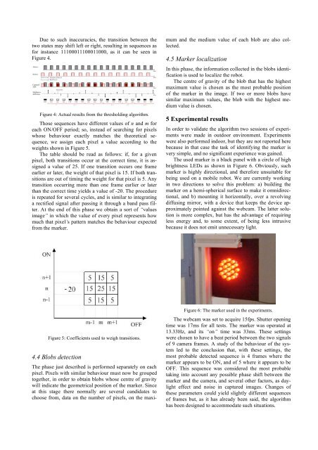
Due to such inaccuracies, the transition between the<br />
two states may shift left or right, resulting in sequences as<br />
<strong>for</strong> instance 11100011100011000, as it can be seen in<br />
Figure 4.<br />
Figure 4: Actual results from the thresholding algorithm.<br />
Those sequences have different values of n <strong>and</strong> m <strong>for</strong><br />
each ON/OFF period; so, instead of searching <strong>for</strong> pixels<br />
whose behaviour exactly matches the theoretical sequence,<br />
we assign each pixel a value according to the<br />
weights shown in Figure 5.<br />
The table should be read as follows: if, <strong>for</strong> a given<br />
pixel, both transitions occur at the correct time, it is assigned<br />
a value of 25. If one transition occurs one frame<br />
earlier or later, the weight of that pixel is 15. If both transitions<br />
are out of timing the weight <strong>for</strong> that pixel is 5. Any<br />
transition occurring more than one frame earlier or later<br />
than the correct time yields a value of -20. The procedure<br />
is repeated <strong>for</strong> several cycles, <strong>and</strong> is similar to integrating<br />
a rectified signal after passing it through a b<strong>and</strong> pass filter.<br />
At the end of this phase we obtain a sort of “values<br />
image” in which the value of every pixel represents how<br />
much that pixel’s pattern matches the behaviour expected<br />
from the marker.<br />
Figure 5: Coefficients used to weigh transitions.<br />
4.4 Blobs detection<br />
The phase just described is per<strong>for</strong>med separately on each<br />
pixel. Pixels with similar behaviour must now be grouped<br />
together, in order to obtain blobs whose centre of gravity<br />
will indicate the geometrical position of the marker. Since<br />
at this stage there normally are several c<strong>and</strong>idates to<br />
choose from, data on the number of pixels, on the maxi-<br />
mum <strong>and</strong> the medium value of each blob are also collected.<br />
4.5 Marker <strong>localization</strong><br />
In this phase, the in<strong>for</strong>mation collected in the blobs identification<br />
is used to localize the <strong>robot</strong>.<br />
The centre of gravity of the blob that has the highest<br />
maximum value is chosen as the most probable position<br />
of the marker in the image. If two or more blobs have<br />
similar maximum values, the blob with the highest medium<br />
value is chosen.<br />
5 Experimental results<br />
In order to validate the algorithm two sessions of experiments<br />
were made in <strong>outdoor</strong> environment. Experiments<br />
were also per<strong>for</strong>med <strong>indoor</strong>, but they are not reported here<br />
because in that case the task of identifying the marker is<br />
very simple, <strong>and</strong> no significant experience was gained.<br />
The used marker is a black panel with a circle of high<br />
brightness LEDs as shown in Figure 6. Obviously, such<br />
marker is highly directional, <strong>and</strong> there<strong>for</strong>e unsuitable <strong>for</strong><br />
being used on a mobile <strong>robot</strong>. We are currently working<br />
in two directions to solve this problem: a) building the<br />
marker on a hemi-spherical surface to make it omnidirectional,<br />
<strong>and</strong> b) mounting it horizontally, over a revolving<br />
diffusing mirror, with a device that keeps the device approximately<br />
pointed against the webcam. The latter solution<br />
is more complex, but has the advantage of requiring<br />
less energy <strong>and</strong>, to some extent, of being less intrusive<br />
because it does not emit unnecessary light.<br />
Figure 6: The marker used in the experiments.<br />
The webcam was set to acquire 15fps. Shutter opening<br />
time was 17ms <strong>for</strong> all tests. The marker was operated at<br />
13.33Hz, <strong>and</strong> its “on” time was 33ms. These settings<br />
were chosen to have a beat period between the two signals<br />
of 9 camera frames. A study of the behaviour of the system<br />
led to the conclusion that, with these settings, the<br />
most probable detected sequence is 4 frames where the<br />
marker appears to be ON, <strong>and</strong> of 5 where it appears to be<br />
OFF. This sequence was considered the most probable<br />
taking into account any possible phase shift between the<br />
marker <strong>and</strong> the camera, <strong>and</strong> several other factors, as daylight<br />
effect <strong>and</strong> noise in captured images. Changes of<br />
these parameters could yield slightly different sequences<br />
of frames but, as it has already been said, the algorithm<br />
has been designed to accommodate such situations.