

69-2042—01 - S8610U Universal Intermittent Pilot Gas Ignition Control
69-2042—01 - S8610U Universal Intermittent Pilot Gas Ignition Control
69-2042—01 - S8610U Universal Intermittent Pilot Gas Ignition Control

Create successful ePaper yourself
Turn your PDF publications into a flip-book with our unique Google optimized e-Paper software.
Table 3. Green LED Status Codes.<br />
Green LED<br />
Flash Code a<br />
Indicates Next System Action Recommended Service Action<br />
OFF No “Call for Heat” Not applicable None<br />
Flash Fast Power up - internal check Not applicable None<br />
Heartbeat Normal startup - ignition<br />
sequence started (including<br />
prepurge)<br />
Not applicable None<br />
4 Seconds ON<br />
then “x” flashes<br />
Device in run mode. "x" = Not applicable<br />
flame current to the nearest<br />
μA.<br />
None<br />
2 5 minute Retry Delay Initiate new trial for ignition after retry delay If system fails to light on next trial for ignition check gas supply,<br />
– <strong>Pilot</strong> flame not detected completed.<br />
pilot burner, spark and flame sense wiring, flame rod<br />
during trial for ignition<br />
contaminated or out of position, burner ground connection.<br />
3 Recycle<br />
Initiate new trial for ignition. Flash code will If system fails to light on next trial for ignition, check gas supply,<br />
– Flame failed during run remain through the ignition trial until flame is pilot burner, flame sense wiring, contamination of flame rod,<br />
proved.<br />
burner ground connection.<br />
4 Flame sensed out of<br />
sequence<br />
If situation self corrects within 10 seconds,<br />
control module returns to normal sequence. If<br />
flame out of sequence remains longer than 10<br />
seconds, control will resume normal operation 1<br />
hour after error is corrected.<br />
Check for pilot flame. Replace gas valve if pilot flame present. If<br />
no pilot flame, cycle “Call for Heat.” If error repeats, replace<br />
control.<br />
5 Damper Error:<br />
– Damper required but not<br />
If damper error corrects, ignition control<br />
resumes normal operation.<br />
Check damper connection, damper wiring, and 24V connection<br />
on control.<br />
present<br />
– Damper failed to open<br />
within 60 seconds<br />
– Damper failed to close<br />
within 60 seconds<br />
Replace damper if necessary.<br />
6 <strong>Control</strong> Internal Error <strong>Control</strong> module remains in wait mode. When the Cycle “Call for Heat.” If error repeats, replace control.<br />
fault corrects, control module resumes normal<br />
operation.<br />
7 Flame rod shorted to ground <strong>Control</strong> module remains in wait mode. When the Check flame sense lead wire for damage or shorting. Check<br />
fault corrects, control module resumes normal that flame rod is in proper position. Check flame rod ceramic for<br />
operation.<br />
cracks, damage or tracking.<br />
8 Low secondary voltage <strong>Control</strong> module remains in wait mode. When the Check transformer and AC line for proper input voltage to the<br />
supply<br />
fault corrects, control module resumes normal<br />
operation.<br />
control. Check with full system load on the transformer.<br />
a Flash Code Descriptions:<br />
- Flash Fast: rapid blinking.<br />
- Heartbeat: Constant ½-second bright, ½-second dim cycles.<br />
- 4-second solid on pulse followed by “x” 1-second flashes indicates<br />
flame current to the nearest mA. This is only available in run mode.<br />
- A single flash code number signifies that the LED flashes X times at 2<br />
Hz, remains off for two seconds, and then repeats the sequence.<br />
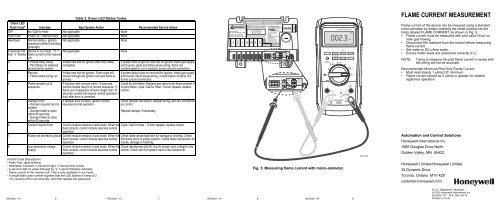
Fig. 5. Measuring flame current with micro-ammeter.<br />
<strong>69</strong>-<strong>2042—01</strong> 6 <strong>69</strong>-<strong>2042—01</strong> 7 <strong>69</strong>-<strong>2042—01</strong> 8 <strong>69</strong>-<strong>2042—01</strong> 9<br />
P1<br />
+<br />
FLAME<br />
–<br />
PRE<br />
PURGE<br />
30 SEC<br />
CURRENT<br />
0 SEC<br />
STATUS<br />
P1<br />
+<br />
–<br />
TRIAL<br />
FOR<br />
IGNITION<br />
15 SEC J1<br />
90 SEC<br />
PRE<br />
PURGE<br />
FLAME<br />
30 SEC<br />
CURRENT<br />
0 SEC<br />
STATUS<br />
TRIAL<br />
FOR<br />
IGNITION<br />
15 SEC J1<br />
90 SEC<br />
002.3<br />
µA<br />
DC<br />
M31283<br />
FLAME CURRENT MEASUREMENT<br />
Flame current of the device can be meaured using a standard<br />
micro-ammeter by simply inserting the meter probes into the<br />
holes labeled FLAME CURRENT, as shown in Fig. 5.<br />
• Flame current must be measured with pilot valve lit but no<br />
main gas flowing.<br />
• Disconnect MV leadwire from the control before measuring<br />
flame current.<br />
• Set meter to DC μAmp scale.<br />
• Ensure meter leads are positioned correctly [+/-].<br />
NOTE: Trying to measure the pilot flame current in series with<br />
the wiring will not be accurate.<br />
Recommended Minimum <strong>Pilot</strong> Only Flame Current:<br />
• Must read steady 1 μAmp DC minimum.<br />
• Flame current should be 2 μAmp or greater for reliable<br />
appliance operation.<br />
Automation and <strong>Control</strong> Solutions<br />
Honeywell International Inc.<br />
1985 Douglas Drive North<br />
Golden Valley, MN 55422<br />
Honeywell Limited-Honeywell Limitée<br />
35 Dynamic Drive<br />
Toronto, Ontario M1V 4Z9<br />
customer.honeywell.com<br />
® U.S. Registered Trademark<br />
© 2010 Honeywell International Inc.<br />
<strong>69</strong>-<strong>2042—01</strong> M.S. Rev. 09-10<br />
Printed in U.S.A.


