

Download PDF - Grundfos
Download PDF - Grundfos
Download PDF - Grundfos
- No tags were found...

You also want an ePaper? Increase the reach of your titles
YUMPU automatically turns print PDFs into web optimized ePapers that Google loves.
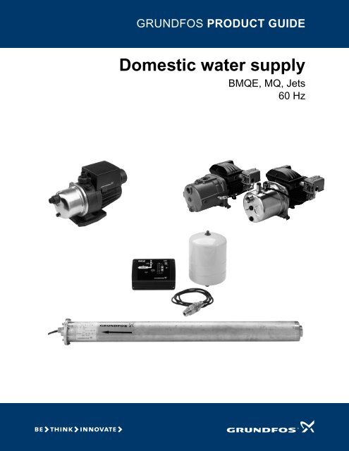
GRUNDFOS PRODUCT GUIDEDomestic water supplyBMQE, MQ, Jets60 Hz
Domestic water supplyTable of contents1. <strong>Grundfos</strong> DWS family 3DWS applications 3DWS product selection 42. BMQE 5Product introduction 5Product overview 7Construction 8Operating conditions 10Installation 10Quick selection guide 12Curve charts and technical data 12Accessories, BMQE 183. MQ 19Product introduction 19Product overview 21Construction 22Operating conditions 24Installation 24Selection of product 24Curve charts and technical data 25Accessories, MQ 284. JP Jet Pumps 29Product introduction 29Product overview 31Construction 34Operating conditions 35Selection 35Selection of pumps 35Installation 35Curve charts and technical data 36Dimensions and weights 41Electrical data 45Approvals 455. Further documentation 46WebCAPS 46WinCAPS 472
Domestic water supply11. <strong>Grundfos</strong> DWS familyThe <strong>Grundfos</strong> Domestic Water Supply (DWS) family ofpumps includes:• BMQE Constant Pressure System• MQ Flow Based Pressure System• Jet pumps.This product guide offers information about each ofthese product lines.DWS applicationsThe <strong>Grundfos</strong> DWS family includes pumps to fit mostapplications including:• Constant pressure systems (BMQE)• flow-based pressure boosting (MQ)• rain water harvesting (MQ)• pressure-switch-based boosting (Jet)• suction lift (Jet).CProductApplicationBMQE MQ JetConstant pressure system • - -Flow-based pressure boosting - • -Rain water harvesting - • -Suction lift - • •Pressure-switch-based boosting - - •Constant pressure systemsIn constant water pressure systems, only the requireddischarge pressure needs setting (fig. 1).Cut-in and cut-out pressures do not play a role in thissystem.Discharge pressure can be set from 40 to 100 psi,according to individual needs and piping systemlimitations.Flow-based pressure boostingWith flow-based pressure boosting, the pump startsautomatically when water is consumed and stopsautomatically when the consumption ceases. This isaccomplished via a flow switch connected to a printedcircuit board (PCB).The pump will produce pressure in relation to the flowrate with any incoming pressure cumulative to the totaldischarge pressure (fig. 2).Incoming psi Outgoing psi =(city water pressure)Incoming psi + performanceFig. 2Flow-based pressure boostingRain water harvestingRain water harvesting is a way to store rain water forfuture use — for example, watering a garden. Rainwater is collected from the roof of a home andcollected into a storage container. Pull a suction liftusing a non-collapsible suction line from the storagecontainer or connect the inlet of the pump to a spigot atthe bottom of the collection barrel for flooded suction.Suction liftHigh pressure water from the drive pipe passesthrough the venturi and pulls water from the well intothe ejector, then pushes it up to the pump. This makesit possible to push water up to the pump from depthsgreater than 25 feet or to boost the output from ashallow well pump to higher pressures.DrivepipeSuction pipeTM01 9873<strong>Grundfos</strong> DWS familyHeadVenturiFig. 1TimeIn a constant pressure system, pressure does notvary in relationship to consumptionTM04 9463 4310Fig. 3InletSuction lift pressure boostingNozzleTM05 0823 1611Pressure-switch-based boostingPressure switches are used to control pump operation.These switches have a cut-in pressure and a cut-outpressure to turn the pump on and off respectively.3
1Domestic water supply<strong>Grundfos</strong> DWS familyDWS product selectionMatching consumption and pumpcapacitySelecting the right pump is a matter of matching waterconsumption with pump capacity. For bestperformance, avoid installing an undersized oroversized pump. Consumption may vary greatlydepending on housing standards and lifestyle. Forexample, lawn sprinkler systems in the summer canincrease consumption.Pump selectionPump selection is based on the water demand andrequired system head.The water demand depends on the number ofconsumers connected to the system.Head can either be expressed in feet or psi. Headrefers to static head, pressure head, and friction head.For assistance with pump selection, refer to theWebCAPS product selection program; a link to CAPSmay be found on the <strong>Grundfos</strong> website.PipingIn any water supply system, the sizing and choice ofmaterials of the pipework has an impact on the choiceof pumps and on the cost. Piping takes into accountthe system head as referred to in Pump Selection.Static head is the distance from the ground water levelto the uppermost tap. Pressure head is the systempressure the user wants to achieve.In most residential application this pressure isapproximately 60 psi. Friction head depends on thepipe size, type and length.When calculating friction loss remember to allow fordeterioration in the piping schematic, since all waterpipes will eventually become coated with rust, limedeposits, etc.Flow velocity in the piping must be kept low as noisecan occur due to turbulence in elbows and valves orfrom water hammer.Fitting a pressure relief valve in the discharge piping isrecommended to protect the piping from over-pressuredue to system malfunction.Pressure tanksA pressure tank should be installed in order tominimize the number of pump starts and stops in thewater supply system, and to reduce problems withwater hammer in the pipework.Tanks are included with the BMQE Constant PressureSystem and the MQ. The BMQE system has anexternal tank. The MQ has an internal tank.Jet pumps, however, may require the addition of a tankdepending upon the application.Pressure switchesPressure switches are used to control pump operation.These switches have a cut-in pressure and a cut-outpressure to turn the pump on and off.The BMQE Constant Pressure System includes apressure transducer for constant pressure. The MQhas a built-in pressure switch. Jet pumps have anattached pressure switch.ValvesCheck valvesA check valve is a mechanical device which normallyallows fluid to flow through in only one direction.The BMQE Constant Pressure System and the MQhave built-in check valves. For suction lift applicationswith the MQ, a check valve (provided) is required atthe inlet.Foot ValvesA foot valve is required when pulling a suction lift(shallow or deep well) with a Jet pump. This valve isinstalled at the end of the suction pipe to prevent backflow. The MQ will also benefit from the use of a footvalve with suction lift applications.Shut off valvesShut off valves in the piping system make it possible todrain only the part of the system that needs attentionor repair.Flow control valvesFlow control valves are used in applications where aset flow (gpm) is required; for example, a shower heador an irrigation system.Pressure reducing valvesPressure reducing valves are used in applicationswhere the incoming water pressure exceeds themaximum inlet pressure of the pump as is the casewith the MQ and city water pressure. The pressurereducing valve (PRV) is used inline after the city watertap and before the pump to ensure a set pressure.Pressure relief valvesThis valve is a spring controlled device that can beadjusted to meet the needs of the pumping system.Pressure relief valves are used in applications wherehigh pressure can result in damage to accessories; forexample, tanks with maximum pressure ratings.4
Domestic water supply22. BMQEProduct introductionThe BMQE Constant Pressure System maintainsconstant water pressure under varying demand, evenwith multiple taps running. The BMQE is a completepressure boosting system that includes:• pump• controller• tank• mounting brackets• pressure sensor.Fig. 4<strong>Grundfos</strong> BMQE Constant Pressure SystemHigh-quality construction and rugged design ensurelow maintenance and trouble-free operation. Thesystem is based on the time-tested technology of the<strong>Grundfos</strong> SQE constant pressure system (forsubmersible applications).The pump's MSE 3 motor incorporates solid stateelectronics and permanent magnet motors whichaccount for high motor efficiencies.Variable speed is offered though frequency control viathe CU 301 remote status box. The system can be setto operate at any duty point in the range betweenminimum and maximum performance of the pump.The BMQE has built in safeties in the solid stateelectronics. The small footprint of the pump allows thesystem to be positioned either vertically or horizontallydepending upon the application. Refer to the BMQE(previously EZ Boost) pages on our web site atwww.grundfos.us.ApplicationsThe BMQE Constant Pressure System is suitable for:• condos• restaurants• homes• irrigation• offices• grocery applications• many other boosting applications.TM04 9387 4010Pumped liquidsThe BMQE Constant Pressure System is suitable forpumping water or other clean, thin, non-aggressiveliquids not containing solid particles or fibers.Features and benefitsWith the <strong>Grundfos</strong> BMQE Constant Pressure System,constant pressure is as simple as a touch of a buttonon the accompanying CU 301 control unit.Features• Quick and easy installation• ready-to-use system requires minimal space• high user convenience (constant pressureregardless of consumption)• easily adjustable pressure level with push buttoncontrol• continuous control and monitoring of pumpoperation• integrated dry-running protection• integrated overload protection• integrated protection against over-voltage andunder-voltage• soft start feature.BenefitsThe BMQE Constant Pressure System automaticallybalances water surges and equalizes flow andpressure according to consumption.In other words, the system maintains a constant waterpressure despite varying consumption.The pressure is registered by means of a pressuresensor and transmitted to the controller. The controlleradjusts the BMQE pump performance accordingly.How the system functionsWhen a tap is opened, the pressure in the tank willstart to drop. The system maintains a constantpressure within the maximum pump performancedespite varying water consumption.The pressure is registered by means of the pressuresensor, which transmits a signal to the controller. Thecontroller adjusts the pump performance accordingly tomaintain constant pressure by changing the pumpspeed.At low flow the pressure will drop slowly. When thepressure in the tank is 7 psi below the setpoint, thepump will start. When the pressure is 7 psi above thesetpoint, the pump will stop.Even though the BMQE controller is controlling thepressure within + / - 3 psi, larger pressure variationsmay occur in the system.BMQE5
2Domestic water supplyBMQEIf the consumption is suddenly changed — forexample, if a tap is opened — the water must startflowing before the pressure can be made constantagain. Such dynamic variations depend on the pipework, but typically they will lie between 7 and 14 psi.If the desired consumption is higher than the quantitythe pump is able to deliver at the desired pressure, thepressure follows the pump curve as illustrated in thefar right of fig. 5.APressureStop+7 PSIStart-7 PSI0.8Controlling±3 PSIA = Pressure settingFig. 5 System functionDynamicvariations±7 PSIFlowGPMAt large flow rates, the pressure will drop quickly andthe pump will start immediately and maintain constantpressure. When the system is running, the controllermakes small adjustments to the pressure to detectwhether there is consumption. If there is none, thepump will simply refill the tank and stop after a fewseconds.BMQE pumpThe pumps used for BMQE system are modified SQEsubmersible pumps. The BMQE pump is an SQE pumpwith an MSE 3 motor. The pump and motor arecentered in the 4 inch stainless steel sleeve.BMQE pumps are suitable for both continuous andintermittent operation for a variety of pressure boostingapplications.BMQE controllerThe BMQE controller is a control and communicationunit specifically developed for the BMQE boosterpumps in constant pressure applications.The controller provides:• Full control of the BMQE pumps• Two-way communication with the BMQE pumps• Possibility of adjusting the pressure• Alarm indication (LED) when service is needed• The possibility of starting, stopping and resetting thepump simply by means of a push-button.The controller communicates with the pump via powerline communication, meaning that no extra cables arerequired between the controller and the BMQE pump.The controller incorporates external signal input forpressure sensor and a pump status relay for use withdevices dependant on pump status.TM04 9388 4010BMQE motorThe MSE 3 motors are based on state-of-the-arttechnology within permanent magnets (PM motor),which accounts for the high motor efficiencies. Inaddition, the motors have a built-in electronic unit witha frequency converter for variable frequency and softstarting.The MSE 3 motors features high efficiency within awide load range. The high and flat efficiency curve ofthe PM motor enables the same motor to cover a widepower range as opposed to conventional AC motors.For BMQE pumps, this means fewer motor variants.Diaphragm tankThe pre-charge pressure of the diaphragm tank mustbe set to 70 % of the pressure setting in order to usethe tank to the limit of its capacity.Use the values in the following table. Pre-chargepressure is measured with 0 psi in the pipeline.Only a 2-gallon tank (<strong>Grundfos</strong> part number 91121984)is recommended in the BMQE system. Use of adifferent size tank will result in pressure fluctations.IdentificationType keySetting (psi)Pre-charge pressure (psi)40 2850 3560 4270 4980 5690 63100 70Example 22 BMQ E 05B 120Rated flow [US gpm]BMQE pumpElectronically controlled pumpvia BMQE controllerMotor [Hp]Head at rated flow [ft]6
Domestic water supply2Product overviewPerformance range, BMQE 60 HzBMQEP[psi]H[ft]15 BMQE 07B-180BMQE60 HzH[m]120280801002408020022 BMQE 10C-1906015 BMQE 05A-110160604012022 BMQE 05B-120408022 BMQE 05A-8030 BMQE 10C-13020204030 BMQE 05B-90000 5 10 15 20 25 30 35 Q[USGPM]0 1 2 3 4 5 6 7 8 9 Q[m³/h]0TM05 0676 1411Product range, BMQERange BMQE 15 BMQE 22 BMQE 30Nominal flow rate [US gpm (m 3 h)] 15 (3.4) 22 (5.0) 30 (6.8)Liquid temperature range [°F (°C)]+32 to +95°F (0 to +35°C)Maximum inlet pressure [psi (bar)] 217 (15)Minimum inlet pressure [psi (bar)] 8 (0.5)Maximum working pressure [psi (bar)] 347 (23)Maximum efficiency [%] 57 62 60Flow range [US gpm (m 3 h)] 0 to 19 (4.3) 0 to 33 (7.5) 0 to 39 (8.8)Maximum pump pressure [ft (m)/psi)] 300 (91.4)/130 290(88.4)/125 208(63.4)/90Pipe connection1.25" NPT inlet / 1” NPT discharge7
2Domestic water supplyBMQESystem diagramTM04 9415 4110Pos. Description1 BMQE pump2 BMQE controller3 Diaphragm tank*4 Pressure sensor5 Mounting brackets6 Flex connector*** Recommended size:2 U.S. gal (8 liter) / 130 psi** Not sold by <strong>Grundfos</strong>ConstructionComponents, BMQEPos.Description6285 4 713TM05 0678 14111 Sleeve2 Discharge connection3 Suction connection4 MSE 3 motor5 SQE pump6 Cable entry7 Centering device8 Air vent screwComponents, BMQE controller612 345TM05 0719 1511Pos. Description1 Flow indicator2 System pressure setting3 System ON/OFF4 Button lock indicator5 Dry-running indicator6 Service needed in case of:• No contact to pump• Over voltage• Under voltage• Speed reduction• Over temperature• Overload• Sensor defective8
Domestic water supply2Material specificationSleevePos. Description Material AISI90 Sleeve Stainless steel 31691 Flange Stainless steel 30492 Cable entry Stainless steel/FKM 30493 Air vent screw Stainless steel 30494 O-ring FKMPumpPos. Description Material AISI1 Valve casing Polyamide 3041a Discharge chamber Stainless steel1d O-ring NBR rubber2 Valve cup Polyamide3 Valve seat NBR rubber4a Empty chamber Polyamide6 Top bearing NBR rubber7 Neck ring TPU / PBT7a Lock ring Stainless spring steel 3107b Neck ring retainer Polyamide9b Chamber top Polyamide9c Chamber bottom Polyamide13 Impeller with tungsten carbide bearing Polyamide14 Suction interconnector Polyamide14a Ring Stainless steel 30416 Shaft with couplingStainless steel 304Sintered steel18 Cable guard Stainless steel 30418a Screws for cable guard Stainless steel 31618b30 Cone for pressure equalization Polyamide32 Guide vanes Polyamide39 Spring Stainless spring steel 316LN55 Pump sleeve Stainless steel 30464 Priming screw Polyamide70 Valve guide Polyamide86 Lip seal ring NBR rubber87Cone for pressure equalizationcompletePolyamide / NBR rubberMotorPos. Description Material AISI201 Stator Stainless steel 304202 Rotor Stainless steel 304202a Stop ringPP202b FilterPolyester203 Thrust bearing Carbon205 Radial bearing Ceramic220 Motor cable with plug EPR222a Filling plugMS 3: NBRMSE 3: FKM224 O-ring FKM225 Top cover PPS232 Shaft sealMotor liquidKeyNBR = Nitrile Butadiene RubberTPU = Thermoplastic PolyurethanesPBT = Polybutylene TerephthalatePP = PolypropyleneEPR = Ethylene Propylene RubberFKM = VitonPPS = Polyphenylene SulphideMS 3: NBRMSE 3: FKMSML-2222a225232224205202a202b202203Fig. 61a70392311d7a64a9b32139c77b201220233BMQE motorBMQE exploded view14a5564308616141887BMQE pump929391949018b18aBMQE sleeveTM05 0679 1411BMQE9
2Domestic water supplyBMQEOperating conditionsFlow:Max. 39 US gpm (8.9 m3/h)Head: Max. 300 ft (91.4 m)Liquid temperature: Max. 95°F (35°C)Operating pressure: Max. 347 psi (23 bar)Inlet pressure:Min. 8 psi (0.55 bar)Sound-pressure level:The sound pressure level of the BMQEis lower than 74 db[A] at a distance of3 ft (1 m).Controller installationAll BMQE pumps can be connected to BMQEcontrollers. Each BMQE pump must be connected toits own BMQE controller.InstallationLocation of installationThe sound pressure level of the BMQE is
Domestic water supply2BMQE pumps connected in parallelWhen connecting BMQE pumps in parallel (fig. 10) aseparate BMQE controller must be used on eachBMQE pump.Set the pressure on one BMQE 10 psi lower than theother.For BMQE pumps connected in parallel, mount oneabove the other; it is recommended to connect thepipes as shown in fig. 10. This layout ensures that theBMQE pumps are filled with water before starting.Pressure sensor installationThe BMQE controller keeps the pressure constant inthe place where the pressure sensor is positioned.The maximum shielded cable length for the sensormust not exceed 1600 ft (487.7 m).Generator operationPower may be supplied to BMQE pumps by anadequately sized generator. The generator must besized 50 % above the pumps P1 (input power) values.BMQEMotor HpMinimumgenerator size[watts]Recommendedgenerator output[watts]0.33 to 0.50 A 1100 15000.50 to 0.75 B 1700 23001.0 to 1.5 B 2000 3500TM04 9413 4110Fig. 10 Booster unit with two BMQE pumps connected inparallel, mounted one above the otherAdditional considerations when connecting in parallel:• All BMQE modules are supplied with a non-returnvalve.• BMQE modules connected in parallel may also beinstalled vertically.• As venting problems may arise in such installations,it is advisable to install suitable air vent devices.• The BMQE should be positioned with the dischargeand air vent at the top when installed vertically.• When the maximum flow for BMQE pumps inparallel will exceed 35 gpm, a 4-gallon or two2-gallon diaphragm tank(s) should be used.11
2Domestic water supplyBMQEQuick selection guideExample:• The maximum demand is 15 gpm (3.4 m 3 /h).• The pressure required is 70 psi (4.8 bar) systempressure at the taps in the building.• The normal minimum inlet pressure (e.g. citypressure) is 20 psi (1.4 bar)• The additional boost required is 50 psi (3.5 bar) at15 gpm (3.4 m 3 /h).• Select a 15 BMQE 05A-110.Additional (boost)pressure required[psi]Flow required [gpm]5 10 15 20 25 30 35 3990807060504030201015 BMQE 07B-18015 BMQE 05A-11022 BMQE 10C-19022 BMQE 05B-12030 BMQE 10C-13022 BMQE 05A-80 30 BMQE 05B-90Curve charts and technical dataHow to read the curve chartsP[psi]140H[ft]15 BMQE60 HzH[m]10012030080Pump type andfrequency.25007B -180 (5-s tage)1008020060QH curve for theindividual pump.15005A -110 (3-s tage)60404010020The efficiency curve shows theefficiency of the pump. Theefficiency curve is an averagecurve of all the pump typesshown in the chart.20050000 2 4 6 8 10 12 14 16 18 Q[USGPM]The power curves indicatepump input power per stage.0.0 0.5 1.0 1.5 2.0 2.5 3.0 3.5 4.0 4.5 Q[m³/h]P2[kW]P2[hp]Eta[%]0.20.3600.10.00.2 P2400.120Eta0.000 2 4 6 8 10 12 14 16 18 Q[USGPM]TM04 4551 160912
Domestic water supply215 BMQE 60 HzP[psi]140H[ft]15 BMQE60 HzH[m]100BMQE30012025007B -180 (5-s tage)8010020060806015005A -110 (3-s tage)40401002020500000 2 4 6 8 10 12 14 16 18 Q[USGPM]P2[kW]P2[hp]0.0 0.5 1.0 1.5 2.0 2.5 3.0 3.5 4.0 4.5 Q[m³/h]Eta[%]0.20.3600.2P2400.10.1Eta200.00.00 2 4 6 8 10 12 14 16 18 Q[USGPM]0TM05 0772 151113
2Domestic water supplyBMQE22 BMQE 60 HzP[psi]140H[ft]22 BMQE60 HzH[m]1003001208025010020010C -190 (5-s tage)60801506005B -120 (3stage)404010005A -80 (2-stage)2020500000 5 10 15 20 25 30 Q[US GPM]0 1 2 3 4 5 6 7 Q[m³/h]P2[kW]P2[hp]Eta[%]00.6600.44000.2P2Eta2000.00 5 10 15 20 25 30 Q[US GPM]0TM05 0773 151114
Domestic water supply230 BMQE 60 HzP[psi]H[ft]22030 BMQE60 HzH[m]70BMQE9020060801807016010C -130 (3-s tage)506014040501204010005B -90 (2-stage)308030602020401010200000 5 10 15 20 25 30 35 Q[USGPM]0 1 2 3 4 5 6 7 8 9 Q[m³/h]P2[kW]P2[hp]Eta[%]00.6600.4P24000.2Eta2000.00 5 10 15 20 25 30 35 Q[USGPM]0TM05 0774 151115
2Domestic water supplyBMQEWeights and electrical dataModelProductnumberMax.motor output[hp]Ratedvoltage[V]Ratedcurrent[A]Locked rotorcurrent[A]Shippingweight[lb (kg)]15 BMQE 05A-110 91128524 0.845 110-115 9.2 11.1 26 (11.8)22 BMQE 05A-80 91128527 0.845 110-115 7.8 11.1 26 (11.8)15 BMQE 05A-110 91128525 0.845 200-240 4.6 5.0 26 (11.8)15 BMQE 07B-180 91128526 1.408 200-240 7.1 8.0 29 (13.2)22 BMQE 05A-80 91128528 0.845 200-240 3.9 5.0 26 (11.8)22 BMQE 05B-120 91128529 1.408 200-240 5.6 8.0 29 (13.2)22 BMQE 10C-190 91128530 2.320 200-240 9.9 11.1 31 (14.1)30 BMQE 05B-90 91128531 1.408 200-240 6.0 8.0 31 (14.1)30 BMQE 10C-130 91128533 2.320 200-240 9.5 11.1 31 (14.1)Shippingvolume[ft 3 (m 3 )]0.9 (0.025)Dimensional sketch, BMQE pumpABFAir ventscrewTM01 7323 1511AB[in (mm)]C[in (mm)]DimensionsD[in (mm)]E[in (mm)]1.0" NPT 43.3 (1100) 0.8 (20.5) Ø 4.6 (116) Ø 3.5 (88.9) 1.25" NPTFDimensional sketch, BMQE controllerTM05 0720 1511DECCableentryBCBMQEADimensions [in (mm)]A B C7.68 (195) 9.13 (232) 4.49 (114)16
Domestic water supply2Technical data, BMQE pumpMain power supply to pumpStartingStoppingRun-up timeMotor protection1 x 200-240 V –10 % / +6 %, 60 Hz1 x 110-115 V –10 % / +6 %, 60 HzSoft starting.The motor starting current is equal to the highest value stated on the BMQE nameplate.Soft stopping when stopped by the BMQE controllerMaximum: 2 seconds.No limitation to the number of starts/stops per hour.Built into the pump. Protection against:• Dry running• Over voltage and under voltage230 V cuts out at < 150 V and > 280 V115 V cuts out at < 75 V and > 150 V• Overload• Over temperatureThe sound pressure level is < 74 db[A] at a distance of 3 feet (1 meter).BMQESound pressure levelIt is recommended by <strong>Grundfos</strong> that the pump be installed with sound and vibration dampeningequipment such as flexible piping adapters and anti-vibration mounting.*The pump should not be mounted in or adjacent to living quarters.The pump can also be wrapped with sound proofing insulation to reduce noise.*Reset functionBMQE pumps can be reset via BMQE controllerPower factor PF = 1.Operation via generatorPipe connectionStrainerApprovalsWeightVoltage* Not sold by <strong>Grundfos</strong>.It is recommended that the generator output is equal to the motor input power P1 [kW]plus 50 %; min. P1 +10 %, however.1.25” NPT inlet / 1” NPT dischargeHoles of the strainer: ø0.09” (2.3 mm)UL Listed, CE (SQE Pump with MSE 3 motor only)31 lbs. (14.1 kg)1 x 100-240 V –10 % / +6 %, 60 HzTechnical data, BMQE controllerVoltagePower consumption1 x 100-240 V -10 % / +6 %, 60 Hz5 WCurrent consumptionMaximum 130 mA• 2-wire w/ground, 12 AWG TeflonMotor cable• B: Black (Line, Neutral)• G: Green (Ground)Enclosure class NEMA 3R (IP 55)Ambient temperatureIn operation: -22 to +122 °F (-30 to +50 °C). During storage: -22 to +140 °F (-30 to +60 °C)Relative air humidity 95 %Pump cable Maximum length between BMQE controller and pump: 650 ft (198 m)Back-up fuseLoadApprovalsMaximum: 16 AMax. 100 mAUL Listed, CE17
2Domestic water supplyBMQEAccessories, BMQEBMQE constant pressure kitDescriptionBMQE controller andpressure sensorRatingSetting range40 to 100 psi(2.8 to 6.9 bar)Productnumber91128636BMQETM05 0732 / TM05 0733BMQE controllerFig. 11 BMQE constant pressure kitDescriptionRatingProductnumberBMQE controllerSetting range40 to 100 psi(2.8 to 6.9 bar)91121987BMQESensorDescriptionRatingProductnumberTM05 0732 1511Pressure sensor forBMQE controller0 to 120 psi(0 to 8.3 bar),1/2” NPT96437852Fig. 12 BMQE controllerDiaphragm tankDescriptionWeight[lbs (kg)]ProductnumberDiaphragm tank, 2 gal. 5 (2.3) 91121984TM05 0733 1511DimensionsFig. 13 Pressure sensor for BMQE controllerGconnectionD[in (mm)]H[in (mm)]3/4” NPT 8 (203) 12.63 (321)SpecificationsDuty rangePre-charge pressure: 40 psi (2.8 bar)Max. operating pressure: 150 psi (10.3 bar)Max. liquid temperature: 200 °F (93 °C)MaterialsTM05 0734 1511Liner: PolypropyleneFig. 14 Diaphragm tankConnection: Lead-free brassTank: Stainless steel, AISI 30418
Domestic water supply33. MQMQProduct introductionThe <strong>Grundfos</strong> MQ is a compact pump and pressureboosting unit, purpose-designed for domestic watersupply and other applications where a compact andreliable, easy-to-install pump is advantageous. TheMQ is a self-priming multistage centrifugal pump; itself-primes from a well depth of down to 26 ft (8 m)within 5 minutes.The MQ is a complete, all-in-one unit, incorporatingpump, motor, diaphragm tank, pressure and flowsensor, controller and check valve.Fig. 15 <strong>Grundfos</strong> MQApplicationsMQ is suitable for pressure boosting of potable waterand rain water for:• water pressure boosting(max. inlet pressure 40 psi (2.8 bar)• water supply from wells(max. suction lift: 26 ft (8 m).Examples of ideal applications for MQ are:• private homes• farms• market gardens and other large gardens.Pumped liquidsThe MQ is suitable for pumping potable water, rainwater, or other clean, thin, non-aggressive liquids notcontaining solid particles or fibers.Features and benefitsComplete systemThe MQ is a compact, "plug and pump" or all-in-onesolution; there is no need for a separate pressure tank,pressure switch, electrical connections, fittings, or anyother separate items. No maintenance of the pump isrequired. Two versions are available to choose from.InstallationInstallation of the MQ is simple and can be done in amatter of minutes, which means greatly reducedinstallation costs.TM01 9873Outlet connnection can be angled up to 5° to fitexisting pipework.Simple operationThe MQ features a user-friendly control panel withON/OFF button and indicator lights for indication of theoperational state of the pump.Compact designCompact, horizontal design fits even where space islimited (outdoor applications require the use of theProtection Cover, sold separately); no space aroundthe pump is required.Self-primingAs it is self-priming, the MQ is able to pump water froma level below the pump. Provided it is filled with water,the pump is able to lift water from a depth of 26 ft (8 m)in less than 5 minutes. This facilitates installation andstart-up of the pump and provides more reliable watersupply in installations where there is a risk of dryrunning and leakages in suction hose or pipes.Built-in protective functionsBuilt-in protective functions; if exposed to dryrunning, excessive temperature, or any overloadcondition the pump will stop automatically, thuspreventing a motor burnout.Automatic resetIn case of dry running or a similar alarm, the pump willstop. Restarting will be attempted every 30 minutes fora period of 24 hours. The reset function can bedeactivated.Low noise levelSuperior hydraulics and internal cooling combinedresult in very quiet operation, which makes it suitablefor many applications.Pressure tankThe built-in pressure tank reduces the number of startsand stops in case of leakages in the pipe system,causing less wear on the pump.How the MQ functionsThe MQ pump has a small built-in pressure tank,sufficient to ensure that water is readily available fromthe tap. When water is required, the pumpautomatically starts. A non-return valve preventsbackflow.The controller ensures that the pump startsautomatically when water is consumed and stopsautomatically when the consumption ceases. Inaddition, the controller protects the pump in case offaults.19
3Domestic water supplyMQIdentificationType key, MQExample MQ 3 - 35 A - B - A - BVBPPump rangeRated flow [m 3 /h]Max. head [m]Code for pump versionA: standardCode for pipework connectionB: External threadCode for materialsA: StandardCode for shaft sealB: Bellow seal, rubberV: CeramicB: Carbon, resin-impregnatedP: NBR (nitrile rubber)20
[ft]H[psi]P3 MQHz 60[m]HDomestic water supply3Product overviewMQPerformance range, MQ 60 Hz5016070ISO 9906 Annex A45-451406040120-355035100304080253020601520401010205000 2 4 6 8 10 12 14 16 Q [US GPM]0.0 0.5 1.0 1.5 2.0 2.5 3.0 3.5 4.0 Q [m³/h]0TM04 4141 0909Product range, MQRange MQ 3-35 MQ 3-45Maximum flow rate [gpm (m 3 h)] 19 (4.3)Maximum pressure [psi (bar)] 49 (3.4) 63 (4.3)Maximum system pressure [psi (bar)] 109 (7.5)Maximum inlet pressure [psi (bar)] 40 (2.7)Maximum suction lift [ft (m)] 26 (8)Minimum ambient temperature [°F (°C)] 32 (0)Maximum ambient temperature [°F (°C)] 113 (45)Minimum liquid temperature [°F (°C)] 32 (0)Maximum liquid temperature [°F (°C)] 95 (35)Net weight [lbs (kg)] 29 (13.2)Sound pressure level [dB(A)] < 60Tank volume [oz (ml)] 13.5 (399)Air pressure in tank [psi (bar)] 22 to 25 (1.5 to 1.7)ConnectionsPriming and drain plugs1" NPT3/8" GAS21
3Domestic water supplyMQConstructionComponents, MQMQ control panel121342985376TM05 0769 151145Fig. 16 MQ pump componentsPos. Description1 Protective cover (accessory)2 Discharge port3 Suction port4 Drain plug5 Baseplate6 Priming plug7 Shaft access port plug8 Pressure tank9 Control panel6TM05 0691 1411Fig. 17 MQ control panelPos.12DescriptionPower indicator lightIndicates the pump is ready foroperation (green).Indicates the pump is onstandby (red).3 On/Off buttonPump is started and stopped bypressing On/Off button.4 Pump ON (green) Indicates pump is running.5 Auto reset6 Alarm (red)Indicates auto reset function isactive.After an alarm, restarting will beattempted every 30 minutes, fora period of 24 hours.Indicates pump is in alarm state.Manual resetting is possible bypressing On/Off button.22
Domestic water supply3Material specification, MQMQPos. Components Material Pos. Components Material2 Support flange PP + 30 % glass fiber 101 Suction port PPO + 20 % glass fiber4 Chamber PPO + 20 % glass fiber7 Drain and priming plug PPO + 20 % glass fiber103104Shaft seal:Stationary androtating partCarbon/ceramics/NBR rubber10 Self-priming valve PP + 30 % glass fiber 149 Insulation disc PA 5VA (Polyammide)14 Self-priming part PPO + 20 % glass fiber16 Pump sleevePOM: PolyoximetylenNR-rubber: Natural RubberPPO: Polyphenylene OxidesPP: PolypropyleneNBR-rubber: Nitrile-Butadiene RubberStainless steel,DIN W.-Nr. 1.4301, AISI 304150ShaftMotor sleeveStainless steel,DIN W.-Nr 1.4005, AISI 416Stainless steel,DIN W.-Nr 1.4301, AISI 30442 Tank cover PP + 30 % glass fiber HB (f1) 164 Terminal box cover PP + 30 % glass fiber 5VA (f1)49 Impeller PPO + 20 % glass fiber-PTFE 174a Pressure switchPOM + 25 % glass fiber /SIL Rubber (Silicone Rubber)51 Motor cover PP + 30 % glass fiber HB (f1)Pressure switchmembraneSIL Rubber - Silicone Rubber.65 Non-return valve POM + 25 % glass fiber 180 Motor body PP + 30 % glass fiber 5VA (f1)92 ClampStainless steel,DIN W.-Nr 1.4301, AISI 304184 Flow sensor POM + 25 % glass fiber100a Discharge port PPO + 20 % glass fiber O-rings NBR-rubber164 184 174a 6542 109210310415018051TM01 9733 1411Fig. 18 MQ exploded view23
3Domestic water supplyMQOperating conditionsSystem pressure:Max. 109 psi (7.5 bar)Inlet pressure:Max. 40 psi (2.8 bar)Suction lift: Max. 26 ft (8 m)Liquid temperature: 32°F to +95°F (0°C to +35°C)Ambient temperature: 32°F to +113°F (0°C to +45°C)InstallationLocationThe pump is suitable for indoor and outdoorinstallation. It is resistant to sunlight. For outdoorinstallation, the pump must be fitted with a protectivecover (accessory). Should the unlikely event of aninternal leakage occur, pumped liquid will be drainedout from the base and/or end cover instead ofdamaging the pump. Install the pump in such a waythat no undesirable collateral damage can arise.Positioning the pumpMount the pump on the base plate with horizontalsuction port and vertical discharge port.The pump must be installed horizontally.The maximum permissible inclination angle is+/- 18 °.To prevent movement and vibrations, the pump andbase plate can be secured to a solid foundation bymeans of the bolt holes in the base plate.Selection of productMQ is available in two sizes and two voltages.ModelMQ 3-35MQ 3-45Voltage[V]Product number115 96860172230 96860201115 96860195230 9686020724
Domestic water supply3Curve charts and technical dataMQMQ 3-35 60 Hz, suction lift performance curveH[ft]1101009080706050403020100P[psi]48464442403836343230282624222018161412108642026.2 ft23 ft19.7 ft13.1 ftMQ 3-3560 Hz6.6 ft0 1 2 3 4 5 6 7 8 9 10 11 12 13 14 15 16 17 18 19 20Q [US GPM]0.0 0.5 1.0 1.5 2.0 2.5 3.0 3.5 4.0 Q [m³/h]0 ftH[m]3432302826242220181614121086420TM05 2056 4311Provided it is filled with water, the pump is able to lift water from a depth of 26 ft (8 m) in less than 5 minutes.Note: Use with a foot valve in suction lift applications.25
3Domestic water supplyMQMQ 3-45 60 Hz, suction lift performance curveH[ft]1401301201101009080706050403020100P[psi]646260585654525048464442403836343230282624222018161412108642026.2 ft23 ft19.7 ft13.1 ftMQ 3-4560 Hz6.6 ft0 1 2 3 4 5 6 7 8 9 10 11 12 13 14 15 16 17 18 19 20 21 22Q [US GPM]0.0 0.5 1.0 1.5 2.0 2.5 3.0 3.5 4.0 Q [m³/h]0 ftH[m]44424038363432302826242220181614121086420TM05 2057 4311Provided it is filled with water, the pump is able to lift water from a depth of 26 ft (8 m) in less than 5 minutes.Note: Use with a foot valve in suction lift applications.26
Domestic water supply3Dimensional sketch - MQMQADEHBFCGTM01 9799Dimensions [in (mm)]A B C D E F G H9.45 (240) 2 x 3/8 (2 x 9.6) 22.44 (570) 7.56 (192) 12.60 (320) 4.49 (114) 8.58 (218) 12.74 (324)Weights and electrical data-10/+6 % voltage tolerance7.5 ft. power cord with plugModelPartNumberPhase,VoltsAmps P2 Net wt.[lb (kg)]Run Start W HpMQ 3-35 96860172 1X110-120V 8 29 585 0.75 30.1 (13.7)MQ 3-45 96860195 1X110-120V 10 29 725 1 30.2 (13.7)MQ 3-35 96860201 1X220-240V 4 15 565 0.75 30.1 (13.7)MQ 3-45 96860207 1X220-240V 4.8 15 716 1 30.2 (13.7)ApprovalsLiquid PumpDrinking WaterNSF / ANSI 61NSF / ANSI 372Low Lead Content27
3Domestic water supplyMQAccessories, MQMQ protective coverProtects keypad and electronics in outdoorapplications. Required for outdoor applications whereMQ is exposed to the elements. Two Velcro tabs areincluded to help adhere back end of cover to pump.MQprotectivecoverDescription Material Product numberMQ protective coverPolypropylenewith Velcro tabs96693071TM05 0787 151128
Domestic water supply44. JP Jet PumpsProduct introductionThe <strong>Grundfos</strong> JP line of self-priming centrifugal jetpumps is designed for shallow well, deep well, andconvertible shallow well pump applications.JP pumps provide excellent suction capacity.Fig. 19 <strong>Grundfos</strong> JP line (from left to right: JP shallow well;JP deep well; and JP convertible shallow well)Applications<strong>Grundfos</strong> JP pumps are particularly suitable for:• domestic water supply systems• light agricultural• industrial water transfer• home and market gardens.Features and benefitsShallow well - cast ironJP05S-CI, JP07S-CI, JP10S-CI, JP30S-CISingle-stage, shallow well self-priming centrifugalpumps. Features:• Rugged cast iron construction• end suction, top discharge arrangement• technopolymer impeller• built-in ejector complete with clean-out port to clearblockages from nozzle• convenient priming plug for ease of priming and airelimination• ceramic-carbon bellows mechanical seal ensurestrouble-free operation• high quality pressure switch.Shallow well convertible - cast ironJP15S-CI, JP20S-CISingle stage, convertible, self-priming centrifugalpumps. Features:• Rugged cast iron construction• end suction, top discharge arrangement• detachable ejector assembly for deep wellapplicationsTM05 1948 4011• technopolymer impeller• convenient priming plug for ease of priming and airelimination• ceramic-carbon bellows mechanical seal ensurestrouble-free operation• high quality pressure switch.Deep well - cast ironJP05D-CI, JP07D-CI, JP15D-CI, JP20D-CISingle-stage, deep well, self-priming centrifugalpumps. Features:• Rugged cast iron construction• end suction, top discharge arrangement• technopolymer impeller• separate deep well port for connection to Deep WellEjector Kit• convenient priming plug for ease of priming and airelimination• ceramic-carbon bellows mechanical seal ensurestrouble-free operation• high quality pressure switch.Shallow well - stainless steelJP05S-SS, JP07S-SS, JP10S-SSSingle-stage, shallow well self-priming centrifugalpumps constructed of stainless steel. Features:• Corrosion-resistant stainless steel• end suction, top discharge arrangement• technopolymer impeller• built-in ejector complete with clean-out port to clearblockages from nozzle• ceramic-carbon bellows mechanical seal ensurestrouble-free operation• high quality pressure switch.MotorsAll <strong>Grundfos</strong> JP motors are Totally Enclosed andFan-Cooled (TEFC) for quiet operation and superiorprotection in harsh environments. Features:• Stainless steel motor shaft offers excellent corrosionresistance• Double, oversized grease ball bearings aremaintenance-free; sealed for life• Built-in thermal overload protection• Capacitor-run, with no switches to fail• Drive end motor bearing protected bydurable lip seal• Insulation class F• Motor protection IP44• Terminal box protection IP55.JP Jet Pumps29
4Domestic water supplyJP Jet PumpsIdentificationType keyExample JP 05 S CIJet pumpHorsepower03: 1/3 Hp05: 1/2 Hp07: 3/4 Hp10: 1 Hp15: 1-1/2 Hp20 2 Hp30: 3 HpWell typeS: Shallow WellD: Deep WellMaterialCI: Cast IronSS: Stainless SteelEC: Engineered Composite30
Domestic water supply4Product overviewConversion chartOld JPF Shallow Well Cast Iron Jet PumpsType Hp Ph VoltsPressure switchsetting [psi]MaterialnumberType Hp Ph VoltsNew Shallow Well Cast Iron Jet PumpsPressure switchsetting [psi]MaterialnumberJP Jet PumpsJPF3JPF31/21/21111523030-5030-509643041296430413JP05S-CI(JP4-47ASA)JPF4 3/4 1 115 30-50 96430414 JP07S-CIJPF4 3/4 1 230 30-50 96430415 (JP4-54ASA)JP10S-CI(JP4-61ASA)JPF5 1-1/2 1 230 50-70 96430416JP15S-CI(JP5-61ASA)JPF7 2 1 230 50-80 96457277JP20S-CI(JP8-62ASA)JP30S-CI(JP12-51ASA)978550731/2 1 115/230 30-50978550813/4 1 115/230 30-501 1 115/230 30-50 978550851-1/2 1 230 40-60 978550912 1 230 40-60 978550943 1 230 40-60 97855095Old JPF Shallow Well Stainless Steel Jet PumpsNew Shallow Well Stainless Steel Jet PumpsType Hp Ph VoltsPressure switchsetting [psi]MaterialnumberType Hp Ph VoltsPressure switchsetting [psi]MaterialnumberJPS2 1/2 1 115 30-50 96430421 JP05S-SSJPS2 1/2 1 230 30-50 96430422 (JP4-47ASI)JP07S-SS(JP4-54ASI)JPS4 1 1 115 30-50 96430423 JP10S-SSJPS4 1 1 230 30-50 96430424 (JP4-61ASI)1/2 1 115/230 30-50 978550753/4 1 115/230 30-50 978550831 1 115/230 30-50 97855088Old JPF Deep Well Cast Iron Jet Pumps*New Deep Well Cast Iron Jet Pumps*Type Hp Ph VoltsPressure switchsetting [psi]MaterialnumberType Hp Ph VoltsPressure switchsetting [psi]MaterialnumberJDF2 1/2 1 115 30-50 96430417 JP05D-CIJDF2 1/2 1 230 30-50 96430418 (JP4-47DSA)1/2 1 115/230 30-50 97855072JDF4 3/4 1 115 30-50 96430419 JP07D-CIJDF4 3/4 1 230 30-50 96430420 (JP4-54DSA)*Ejector not includedJP15D-CI(JP5-61DSA)JP20D-CI(JP8-62DSA)*Ejector not included3/4 1 115/230 30-50 978550801-1/2 1 230 40-60 978550902 1 230 40-60 9785509331
4Domestic water supplyJP Jet PumpsPerformance rangeH[m]60H[ft]210200JP60 Hzp[psi]908555190180805017016075704515065140604035130120110JP105550301004590402520807060JP05JP07JP15JP20JP3035302515502010403015520101050000 5 10 15 20 25 30 35 40 45 50 55 60Q [US GPM]0 2 4 6 8 10 12 Q [m³/h]TM05 1230 451132
Domestic water supply4Product rangeShallow wellShallow well cast ironShallow well stainless steelModelJP05S-CI JP07S-CI JP10S-CI JP15S-CI JP20S-CI JP30S-CI JP05S-SS JP07S-SS JP10S-SSMax. flow [gpm (m 3 h)] 21 (4.7) 20 (4.5) 20 (4.5) 23 (5.2) 34 (7.7) 52 (11.8) 21 (4.7) 20 (4.5) 20 (4.5)Max. pump head [ft (m)] 145 (44.2) 170 (51.2) 200 (61.0) 210 (64.0) 210 (64.0) 170 (51.2) 145 (44.2) 170 (51.2) 200 (61.0)Max. working pressure [psi (bars)] 116 (8) 116 (8)Motor power [hp] 1/2 3/4 1 1 1/2 2 3 1/2 3/4 1Fluid temp range [°F (°C)] +32 to +95 (0 to +35) +32 to +95 (0 to +35)Max. lift [ft suction lift at sea level] 25 25Max. ambient temp [°F (°C)] +104 (+40) +104 (+40)Factory pressure switch setting[psi (bars)]30/50(2.1/3.5)30/50(2.1/3.5)30/50(2.1/3.5)40/60(2.8/4.1)40/60(2.8/4.1)40/60(2.8/4.1)30/50(2.1/3.5)30/50(2.1/3.5)Storage temp range [°F (°C)] +14 to +104 (-10 to +40) +14 to +104 (-10 to +40)Relative humidity 95% 95%Max. starts per hour 20 2030/50(2.1/3.5)JP Jet PumpsDeep wellModelDeep well cast ironJP05D-CI JP07D-CI JP15D-CI JP20D-CIMax. flow [gpm (m 3 h)] 18 (4.0) 18 (4.0) 21 (4.7) 32 (7.2)Max. pump head [ft (m)] 145 (44.2) 170 (51.2) 195 (59.4) 200 (61.0)Max. working pressure [psi (bars)] 116 (8)Motor power [hp] 1/2 3/4 1 1/2 2Fluid temp range [°F (°C)] +32 to +95 (0 to +35)Max. lift [ft suction lift at sea level] 50 70 90 90Max. ambient temp [°F (°C)] +104 (+40)Factory pressure switch setting [psi(bars)]30/50(2.1/3.5)30/50(2.1/3.5)40/60(2.8/4.1)Storage temp range [°F (°C)] +14 to +104 (-10 to +40)Relative humidity 95%Max. starts per hour 2040/60(2.8/4.1)33
4Domestic water supplyJP Jet PumpsConstructionMaterials of constructionShallow well - cast iron, stainless steel1 4 28 7160 16 3TM05 2216 4611Pos.Descriptions:in contact with liquidMaterialsCast ironmodelsStainless steelmodels1 Pump BodyCast Iron 200 UNI ISO 185 All -Stainless Steel AISI 304 - All3 Support Cast Iron 200 Uni ISO 185 JP15, JP20, JP30 -3 Support Aluminum + AISI304 JP05, JP07, JP10 All4 Impeller Technopolymera All All7 Shaft with RotorStainless Steel AISI 416 All -Stainless Steel AISI 303 - All16 Mechanical Seal Carbon / ceramic All All28 OR Gasket NBR Rubber All All160 Nozzle-Venruri Diffuser Assembly Technopolymera All AllDeep well - cast iron16 4 28 382916 7TM05 2215 4611Pos.Descriptions:in contact with liquidMaterialsCast ironmodels1 Pump Body Cast Iron 200 UNI ISO 185 All3 Support Cast Iron 200 UNI ISO 185 All4 Impeller Technopolymer All6 Diffuser Technopolymer All7 Shaft with RotorStainless Steel ANSI 416JP05 & JP07Stainless Steel ANSI 303JP15 & JP2016 Mechanical Seal Carbon/Ceramic All28 OR Gasket NBR Rubber All2 Ejector Body Cast Iron 200 UNI ISO 185 E20, E25, E308 Venturi Tube Technopolymer E20, E25, E309 Nozzle Brass E20, E25, E3034
Domestic water supply4Operating conditionsMax. operating pressure:116 psi (8 bar)Liquid temp range:+32 °F to +95 °F (0 °C to +35 °C)Max. relative humidity of air 95%Storage temp range:+14 °F to +104 °F (-10 °C to 40 °C)SelectionPumped liquidsJP pumps are suitable for pumping clean, non-viscous,non-aggressive, non-explosive liquids, free of solidparticles or fibers.InstallationPump locationThe pump must be located in a well-ventilated place,protected from unfavorable weather conditions andwith an environmental temperature not exceeding104 °F (40 °C).It is always good practice to place the pump as closeas possible to the liquid to be pumped.Pump positionAllowable positionsJP Jet PumpsSelection of pumpsPumptypeHpShallow well - cast ironPhVolts[V]Pressureswitchsetting[psi]ProductnumberJP05S-CI 1/2 1 115/230 30-50 97855073JP07S-CI 3/4 1 115/230 30-50 97855081JP10S-CI 1 1 115/230 30-50 97855085JP15S-CI 1-1/2 1 230 40-60 97855091JP20S-CI 2 1 230 40-60 97855094JP30S-CI 3 1 230 40-60 97855095Shallow well - stainless steelFig. 20 Pump must be installed in horizontal position onlyThe pump must be installed only in horizontal position.To prevent movement and vibrations, anchor the pumpfirmly to a horizontal surface.TM05 1232 2411PumptypeHpPhVolts[V]Pressureswitchsetting[psi]ProductnumberJP05S-SS 1/2 1 115/230 30-50 97855075JP07S-SS 3/4 1 115/230 30-50 97855083JP10S-SS 1 1 115/230 30-50 97855088Deep well - cast iron*PumptypeHpPhVolts[V]Pressureswitchsetting[psi]ProductnumberJP05D-CI 1/2 1 115/230 30-50 97855072JP07D-CI 3/4 1 115/230 30-50 97855080JP015D-CI 1-1/2 1 230V 40-60 97855090JP020D-CI 2 1 230V 40-60 97855093* Ejector not includedDeep well ejectorsTypeProductnumberE20 NPT 96654382E25 NPT 96654383E30 NPT 9665438435
4Domestic water supplyJP Jet PumpsCurve charts and technical dataPerformance curvesModels JP05S-CI, JP05S-SSH[m]454035302520151050H[ft]1501401301201101009080706050403020100QHJP0560 Hz0 2 4 6 8 10 12 14 16 18 20 22 24Q [US GPM]0.0 0.5 1.0 1.5 2.0 2.5 3.0 3.5 4.0 4.5 Q [m³/h]p[psi]65605550454035302520151050TM05 1137 5111Models JP07S-CI, JP07S-SSH[m]50H[ft]180160QHJP0760 Hzp[psi]80704014012060503020100806040301040202010000 2 4 6 8 10 12 14 16 18 20 22 24Q [US GPM]0.0 0.5 1.0 1.5 2.0 2.5 3.0 3.5 4.0 4.5 Q [m³/h]0TM05 1139 511136
Domestic water supply4Models JP10S-CI, JP10S-SSH[m]60H[ft]200180QHJP1060 Hzp[psi]80JP Jet Pumps50160704030201014012010080604020605040302010000 2 4 6 8 10 12 14 16 18 20 22 24Q [US GPM]0.0 0.5 1.0 1.5 2.0 2.5 3.0 3.5 4.0 4.5 Q [m³/h]0TM05 1141 5111Model JP15S-CIH[m]60H[ft]220200180QHJP1560 Hzp[psi]908050160704030201014012010080604020605040302010000 2 4 6 8 10 12 14 16 18 20 22 24 26Q [US GPM]0.0 0.5 1.0 1.5 2.0 2.5 3.0 3.5 4.0 4.5 Q [m³/h]0TM05 1147 511137
4Domestic water supplyJP Jet PumpsModel JP20S-CIH[m]60H[ft]220200180QHJP2060 Hzp[psi]9080501607040140120605030201010080604020403020100000 4 8 12 16 20 24 28 32 36 40Q [US GPM]0 1 2 3 4 5 6 7 Q [m³/h]TM05 1148 5111Model JP30S-CIH[m]50H[ft]180160QHJP3060 Hzp[psi]807040140120605030201008060403010402020100000 4 8 12 16 20 24 28 32 36 40 44 48 52 56Q [US GPM]0 1 2 3 4 5 6 7 8 9 10 Q [m³/h]TM05 1150 511138
Domestic water supply4Shallow well performance dataPumptypePartnumbercast ironPartnumberstainlesssteelPressureswitchsettingon/offJP05S 97855073 97855075 30/50JP07S 97855081 97855083 30/50JP10S 97855085 97855088 30/50JP15S 97855091 - 40/60JP20S 97855094 - 40/60JP30S 97855095 - 40/60Suctiondepth[ft]Delivery pressure [psi]15 20 25 30 35 40 45 50 55 60 65Flow table [gpm]Max.pressure[psi]Shut offpressure[psi]5 14.8 14.8 14.7 13.6 - - - - - - -5910 13.2 13.2 13.1 12.8 - - - - - - - 5715 - 10.8 10.8 10.7 10.1 - - - - - - 62 5520 - - 8.9 8.9 8.8 7.6 - - - - - 5325 - - 7.0 7.0 7.0 6.9 5.5 - - - - 515 - - 14.3 14.3 14.2 12.6 - - - - -7310 - - 13.1 13.1 13.0 12.3 - - - - - 7015 - - - 11.0 11.0 11.0 10.0 - - - - 75 6820 - - - 9.2 9.1 9.1 9.0 - - - - 6625 - - - - 7.0 7.0 7.0 6.9 - - - 645 - - - 14.5 14.4 14.3 14.2 - - - -8410 - - - - 13.1 12.8 12.7 12.4 - - - 8215 - - - - - 11.8 11.6 11.4 10.9 - - 86 8020 - - - - - 9.9 9.8 9.7 9.4 - - 7725 - - - - - - - 7.9 7.8 7.7 7.3 755 - 21.0 20.9 20.7 20.6 20.3 20.2 19.9 - - -8510 - 19.0 18.8 18.5 18.2 17.9 17.8 17.5 17.3 - - 8215 - - 15.7 15.5 15.4 15.2 15.1 15.0 14.8 14.5 - 87 8020 - - - 13.3 13.1 12.9 12.7 12.5 12.4 12.1 11.9 7825 - - - - 9.7 9.5 9.3 9.1 8.9 8.6 8.5 765 - 31.8 31.6 31.2 30.8 30.5 30.1 29.1 - - -8310 - 28.0 27.7 27.6 27.2 26.9 26.7 26.0 25.1 - - 8115 - 23.6 23.3 23.2 23.1 22.8 22.5 22.3 22.1 20.9 - 85 7920 - - 20.2 19.9 19.8 19.7 19.4 19.3 19.0 18.5 17.3 7625 - - - - 14.3 14.2 14.1 13.8 13.7 13.4 13.2 745 - 49.5 49.3 48.9 47.9 46.8 - - - - -7110 - 46.0 45.4 45.0 44.5 43.6 42.0 - - - - 6915 - 37.1 36.8 36.5 36.1 35.5 34.7 33.5 - - - 73 6720 - 32.1 31.8 31.6 31.2 30.6 30.4 29.3 25.9 - - 6425 - 20.9 20.7 20.6 20.4 20.0 19.5 18.8 18.0 16.5 13.8 62JP Jet Pumps39
4Domestic water supplyJP Jet PumpsDeep well performance dataPumptypePumppartnumberEjectortypeNPTEjectorpartnumberPressureswitchon/offSuctiondepth[ft]Delivery pressure [psi]20 30 40 50 60 70 80 90Flow table [gpm]JP05D 97855072JP07D 97855080JP15D 97855090JP20D 97855093E 25 96654383 30/50E 30 96654384 30/50E 25 96654383 30/50E 30 96654384 30/50E 20 96654382 40/60E 25 96654383 40/60E 30 96654384 40/60E 20 96654382 40/60E 25 96654383 40/60E 30 96654384 40/6030 8 5 - - - - - -40 6 3 - - - - - -50 4 1.5 - - - - - -30 7.7 5.8 2.5 1.3 - - - -40 5.9 4.3 1.6 - - - - -50 5 3.4 1 - - - - -30 10.5 7.9 2.5 - - - - -40 8.5 5.4 - - - - - -50 6.4 3.5 - - - - - -40 - 5.6 2.8 1.7 - - - -50 - 4.6 2.2 1.3 - - - -60 - 3.5 1.5 - - - - -70 - 2.9 - - - - - -30 - - 15 12.2 9.2 2.6 - -40 - - 13.5 10.6 7.6 - - -50 - - 11.6 8.8 5.5 - - -60 - - 10 7 3.6 - - -50 - - 12 9.8 7.7 3.5 - -60 - - 10.8 8.6 6.5 2.5 - -70 - - 9.7 7.5 5.3 1.7 - -70 - - 7.9 7.1 6 3.8 2 -80 - - 7.2 6.5 5.3 3.2 1.6 -90 - - 6.7 5.8 4.7 2.8 1.2 -30 - - - 15 9 2 - -40 - - - 13.4 6.8 - - -50 - - - 11.7 5 - - -60 - - - 9.9 2.9 - - -50 - - - 12.5 7.9 3.7 2 -60 - - - 11.1 6.7 2.8 1.2 -70 - - - 9.9 5.5 1.8 - -80 - - - 8.6 4.3 1 - -70 - - - 7.9 6.2 4 3 2.380 - - - 7.3 5.6 3.4 2.7 1.990 - - - 6.7 5 3 2.3 1.540
Domestic water supply4Dimensions and weightsCast iron shallow well, model JP05S-CIDNACDNMAA1H3JP Jet PumpsHEFBØ IGTM05 2221 4611ModelPartnumberDimensions [in]A A1 B C E F G H H3 I DNA DNMWeight[lbs]JP05S-CI 97855073 15.7 15.5 10.4 4.2 7.6 0.5 4.4 8.1 5.6 0.4 1 1 24Cast iron shallow well, models JP07S-CI, JP10S-CIACDNMA1H2H1HDNAEFBIGTM05 2222 4611ModelPartnumberDimensions [in]A A1 B C E F G H H1 H2 I DNA DNMWeight[lbs]JP07S-CI 97855081 16.5 16.3 10.4 4.2 7.6 0.5 4.4 8.5 7 5.6 0.4 1 1 28JP10S-CI 97855085 16.5 16.3 10.4 4.2 7.6 0.5 4.4 8.5 7 5.6 0.4 1 1 3041
4Domestic water supplyJP Jet PumpsCast iron shallow well, models JP15S-CI, JP20S-CIACDNMDNAH1HEFBGITM05 2365 5011ModelPartnumberDimensions [in]A B C E F G H H1 I DNA DNMWeight[lbs]JP15S-CI 97855091 21.8 10.2 8.7 13.5 0.5 5.7 10 6.2 0.6 1.25 1 68JP20S-CI 97855094 21.9 10.2 8.7 13.5 0.5 5.7 10 6.2 0.6 1.25 1 77Cast iron shallow well, models JP30S-CIDNACDNMAH1HEFBGITM05 2366 5011ModelPartnumberDimensions [in]A B C E F G H H1 I DNA DNMWeight[lbs]JP30S-CI 97855095 23.4 10.3 5.9 11.3 0.6 6.3 10.4 7.6 0.4 1.5 1.25 7142
Domestic water supply4Shallow well stainless steel, model JP05S-SS1"NPTAC1"NPTH3JP Jet PumpsHEFBØ IGTM05 2219 4611PartDimensions [in]WeightModelnumber[lbs]A B C E F G H H3 IJP05S-SS 97855075 16 10.4 4.7 8.1 0.6 4.4 8.3 5.6 0.4 18Shallow well stainless steel, models JP07S-SS, JP10S-SSC1"NPTAH2H1H1"NPTEFBIGTM05 2220 4611ModelPartnumberDimensions [in]A B C E F G H H1 H2 IWeight[lbs]JP07S-SS 97855083 16.8 10.4 4.7 8.1 0.6 4.4 8.5 7.7 5.7 0.4 22JP10S-SS 97855088 16.8 10.4 4.7 8.1 0.6 4.4 8.5 7.7 5.7 0.4 2443
4Domestic water supplyJP Jet PumpsCast iron deep well, models JP05D-CI, JP07D-CICDNMAA1H1DNEHDNAEFH2BØ IGTM05 2218 4611ModelPartnumberDimensions [in]A A1 B C E F G H H1 H2 I DNA DNE DNMWeight[lbs]JP05D-CI 97855072 15 14.6 10.4 3.4 6.7 0.5 4.4 8.1 3.7 1.9 0.4 1.25 1 1 25JP07D-CI 97855080 15.8 15.4 10.4 3.4 6.7 0.5 4.4 8.5 3.7 1.9 0.4 1.25 1 1 25Cast iron deep well, models JP15D-CI, JP20D-CIDNMADNE DNACEFA1BH1H2HGITM05 2367 5011ModelPartnumberDimensions [in]A A1 B C E F G H H1 H2 I DNA DNE DNMWeight[lbs]JP15D-CI 97855090 15.9 15.2 10.2 2 6.7 0.5 5.7 10 2.1 4.2 0.6 1.25 1 1 63JP20D-CI 97855093 18.9 18.2 10.2 2 6.7 0.5 5.7 10 2.1 4.2 0.6 1.25 1 1 7244
Domestic water supply4Electrical dataSupply voltage:1 X 115/230V 60Hz1 X 230V 60HzVoltage tolerance + / - 6 %JP Jet PumpsElectrical data 60 HzPumpModelPartNumberP2Power Out[Hp]Servicefactor[Hp]Phase &voltageI[amps]Phase &voltageI[amps]Capacitor[uF]JP05D-CI 97855072 1/2 1.60 1x115 7.09 1x230 3.61 50JP05S-CI 97855073 1/2 1.60 1x115 8.21 1x230 4.22 50JP05S-SS 97855075 1/2 1.60 1x115 8.21 1x230 4.22 50JP07D-CI 97855080 3/4 1.5 1x115 9.2 1x230 4.67 50JP07S-CI 97855081 3/4 1.5 1x115 10.3 1x230 5.25 50JP07S-SS 97855083 3/4 1.5 1x115 10.3 1x230 5.25 50JP10S-CI 97855085 1 1.40 1x115 13.8 1x230 7.1 80JP10S-SS 97855088 1 1.40 1x115 13.8 1x230 7.1 80JP15D-CI 97855090 1-1/2 1.3 - - 1x230 7.6 31.5JP15S-CI 97855091 1-1/2 1.3 - - 1x230 8 31.5JP20D-CI 97855093 2 1.25 - - 1x230 8.5 40JP20S-CI 97855094 2 1.25 - - 1x230 11 40JP30S-CI 97855095 3 1.15 - - 1x230 12 40Note: Refer to pump nameplate.ApprovalsLiquid PumpSubject to alterations.45
5Domestic water supplyFurther documentation5. Further documentationWebCAPSWebCAPS is a Web-based Computer Aided ProductSelection program available on www.grundfos.com.WebCAPS contains detailed information on more than185,000 <strong>Grundfos</strong> products in more than 20 languages.In WebCAPS, all information is divided into 6 sections:• Catalog• Literature• Service• Sizing• Replacement• CAD drawings.CatalogThis section is based on fields of application and pump types, andcontains• technical data• curves (QH, Eta, P1, P2, etc) which can be adapted to thedensity and viscosity of the pumped liquid and show thenumber of pumps in operation• product photos• dimensional drawings• wiring diagrams• quotation texts, etc.LiteratureIn this section you can access all the latest documents of a givenpump, such as• product guides• installation and operating instructions• service documentation, such as Service kit catalogand Service kit instructions• quick guides• product brochures, etc.ServiceThis section contains an easy-to-use interactive service catalog.Here you can find and identify service parts of both existing anddiscontinued <strong>Grundfos</strong> pumps.Furthermore, this section contains service videos showing you howto replace service parts.46
0 1Domestic water supply5SizingThis section is based on different fields of application andinstallation examples, and gives easy step-by-step instructions inhow to• select the most suitable and efficient pump for your installation• carry out advanced calculations based on energy consumption,payback periods, load profiles, life cycle costs, etc.• analyze your selected pump via the built-in life cycle cost tool• determine the flow velocity in wastewater applications, etc.Further documentationReplacementIn this section you find a guide to selecting and comparingreplacement data of an installed pump in order to replace the pumpwith a more efficient <strong>Grundfos</strong> pump.The section contains replacement data of a wide range of pumpsproduced by other manufacturers than <strong>Grundfos</strong>.Based on an easy step-by-step guide, you can compare <strong>Grundfos</strong>pumps with the one you have installed on your site. When you havespecified the installed pump, the guide will suggest a number of<strong>Grundfos</strong> pumps which can improve both comfort and efficiency.CAD drawingsIn this section it is possible to download 2-dimensional (2D) and3-dimensional (3D) CAD drawings of most <strong>Grundfos</strong> pumps.These formats are available in WebCAPS:2-dimensional drawings:• .dxf, wireframe drawings• .dwg, wireframe drawings.3-dimensional drawings:• .dwg, wireframe drawings (without surfaces)• .stp, solid drawings (with surfaces)• .eprt, E-drawings.WinCAPSFig. 21 WinCAPS CD-ROMWinCAPS is a Windows-based Computer AidedProduct Selection program containing detailedinformation on more than 185,000 <strong>Grundfos</strong> products inmore than 20 languages.The program contains the same features and functionsas WebCAPS, but is an ideal solution if no Internetconnection is available.WinCAPS is available on CD-ROM and updated once ayear.47
Being responsible is our foundationThinking ahead makes it possibleInnovation is the essenceL-DWS-PG-01 0612ECM: -The name <strong>Grundfos</strong>, the <strong>Grundfos</strong> logo, and the payoff Be–Think–Innovate are registrated trademarksowned by <strong>Grundfos</strong> Management A/S or <strong>Grundfos</strong> A/S, Denmark. All rights reserved worldwide.GRUNDFOS Pumps Corporation17100 West 118th TerraceOlathe, Kansas 66061Phone: +1-913-227-3400Telefax: +1-913-227-3500GRUNDFOS Canada Inc.2941 Brighton RoadOakville, Ontario L6H 6C9CanadaPhone: +1-905 829 9533Telefax: +1-905 829 9512Bombas GRUNDFOS de Mexico S.A. de C.V.Boulevard TLC No. 15Parque Industrial Stiva AeropuertoApodaca, N.L. Mexico 66600Phone: +52-81-8144 4000Telefax: +52-81-8144 4010


