VERSANAIL Tibial Nailing System Surgical Technique - Biomet
VERSANAIL Tibial Nailing System Surgical Technique - Biomet
VERSANAIL Tibial Nailing System Surgical Technique - Biomet

Create successful ePaper yourself
Turn your PDF publications into a flip-book with our unique Google optimized e-Paper software.
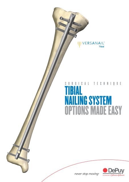
S U R G I C A L T E C H N I Q U E<br />
TIBIAL<br />
NAILING SYSTEM<br />
OPTIONS MADE EASY
TABLE OF CONTENTS<br />
DESIGN SUMMARY<br />
INSTRUMENT OVERVIEW AND JIG OPTIONS<br />
ENTRY AND CANAL PREP<br />
NAIL INSERTION<br />
LOCKING<br />
NAIL REMOVAL<br />
BLOCKING SCREW TECHNIQUE<br />
ESSENTIAL PRODUCT INFORMATION<br />
IMPLANTS<br />
INSTRUMENT CATALOGUE NUMBERS AND DESCRIPTIONS<br />
1<br />
2<br />
3<br />
6/7<br />
Note: This brochure presents a surgical technique available for use with the DePuy<br />
<strong>VERSANAIL</strong> Platform instruments and implants. Surgeons may need to make modifications<br />
as appropriate in their own surgical technique with these devices depending on individual<br />
patient requirements.<br />
7<br />
12<br />
13<br />
14<br />
15<br />
16
MADE EASY<br />
The DePuy Trauma and Extremities Group’s <strong>VERSANAIL</strong> <strong>Tibial</strong><br />
Nail <strong>System</strong> is part of a long bone nailing system that offers a<br />
complete portfolio of implants and instruments based on a single,<br />
standardised technology platform.<br />
OPTIONS<br />
DESIGN SUMMARY<br />
The <strong>Tibial</strong> Nail <strong>System</strong> from the <strong>VERSANAIL</strong> Platform offers an optimal<br />
implant design to treat a range of tibia fractures from simple to complex,<br />
with versatile locking options. The <strong>VERSANAIL</strong> Platform instrumentation is<br />
designed to provide options and flexibility for many intraoperative<br />
approaches (including percutaneous methods) while maintaining ease of use<br />
and commonality.<br />
IMPLANT MATERIAL<br />
All implants are manufactured from 6Al-4V ELI grade, type II anodised titanium<br />
alloy (TIMAX) due to this material’s superior properties. TIMAX offers a lower<br />
modulus of elasticity and increased fatigue strength over stainless steel.<br />
1<br />
DESIGN SUMMARY
INSTRUMENT OVERVIEW AND JIG OPTIONS 2<br />
Instruments<br />
The <strong>VERSANAIL</strong> Platform instrumentation system is designed to be intuitive,<br />
enabling a simpler and more efficient procedure. The <strong>VERSANAIL</strong> Platform’s modular<br />
nature facilitates the use of common instruments across all <strong>VERSANAIL</strong> nailing<br />
systems, reducing confusion among the OR staff. For example, <strong>VERSANAIL</strong><br />
Platform jigs look and function the same way, and common instruments (such as<br />
awls, entry portals, guide wires, nail length gauge, locking instrumentation and screw<br />
caddies) can be used across all <strong>VERSANAIL</strong> Platform nailing systems.<br />
Jig Options<br />
Two jig options are available for the <strong>VERSANAIL</strong> <strong>Tibial</strong> Nail and are designed to<br />
accommodate varying approaches to incision placement.<br />
Fig. 1 The low-profile jig allows radiolucent targeting and is<br />
designed with a very low-profile jig nose (Fig.1). This makes<br />
it useful for a standard approach, such as a split-patella<br />
tendon technique, which requires instrumentation that will not<br />
impinge on the patella during nail insertion and allows greater<br />
limb extension during locking.<br />
Fig. 2 The extended tibia jig features an extended nose, to<br />
accommodate a higher incision point, for a more percutaneous<br />
approach if desired (Fig. 2). This jig is designed with the jig<br />
mechanics up and out of the way so that the entry site can<br />
be targeted from a distance. The targeting arm rotates with<br />
the push of a button to target the proximal locking options.<br />
The rotating design also allows the jig to be repositioned for<br />
convenience during the nailing procedure without disassembly<br />
to improve visualisation of the nail seating and screw length.<br />
Locking instrumentation is colour-coded by screw size for simplicity:<br />
Colour Guide Screw Size Drill Bit Size Instruments<br />
Proximal Locking–Purple 5.5 mm 4.4 mm Sheath, Trocar, Drill Guide<br />
Distal Locking–Green 4.5 mm 3.8 mm Calibrated Drill Sleeve
Fig. 3<br />
Fig. 4<br />
Patient Positioning<br />
Position the patient supine on a radiolucent table (Fig. 3).<br />
Knee flexion will assist with identification of the anatomic<br />
landmarks to allow accurate incision placement. For ease of<br />
distal locking from the medial direction, it is helpful to place<br />
the C-arm on the opposite side of the injured limb.<br />
Entry Site and <strong>Surgical</strong> Approach<br />
Make a proximal incision along the medial aspect of the<br />
patellar tendon (Fig. 4). For more proximal fractures a lateral<br />
peri-tendinous approach may be beneficial based on surgeon<br />
preference. Continue deep dissection until the proximal<br />
aspect of the tibia is encountered.<br />
Fig. 5 A starting point is made either with a 3.6 mm x 14 in.<br />
guide pin (Cat. No. 2810-01-036) or an awl, based on<br />
surgeon preference (Fig. 5). Use AP and lateral fluoroscopic<br />
views to confirm accurate placement. For midshaft and distal<br />
tibia fractures, a central starting point in the AP view is<br />
adequate. For more proximal fractures, however, a slightly<br />
lateral starting point is recommended to avoid proximal<br />
fragment malalignment.<br />
Fig. 6 Use the awl (Cat. No. 2810-01-005) or 11.5 mm<br />
cannulated entry reamer (Cat. No. 2810-12-028) to open the<br />
proximal tibia. If required, an entry portal sleeve (Cat. No.<br />
2810-12-001) is available for soft tissue protection (Fig. 6).<br />
ENTRY AND CANAL PREP 3
4<br />
If dynamic locking is<br />
planned, ream to the most<br />
proximal groove on the<br />
shaft of the entry reamer.<br />
Canal Preparation<br />
Fig. 7 Fluoroscopically verify the entry point and advance the<br />
awl or 11.5 mm entry reamer in line with the tibial canal<br />
(Fig. 7). The entry reamer is marked to identify the correct<br />
reaming depth depending on whether dynamisation will be<br />
used. The tibial nail dynamisation range is 7 mm.<br />
Fig. 8 Once access to the tibial canal has been gained, place the<br />
ball nose guide wire into the entry site utilising the guide wire<br />
gripper. Two guide wire gripper styles are available depending<br />
on surgeon preference: the pistol grip (Cat. No. 2810-01-001)<br />
or the T-handle grip (Cat. No. 2810-01-002) (Fig. 8).<br />
Fig. 9<br />
Fracture Reduction<br />
Obtain appropriate anatomic reduction in order to restore<br />
length, alignment and rotation of the injured limb. Reduction<br />
can be achieved through the surgeon’s preferred method<br />
such as traction and/or an external fixator. To aid in<br />
manipulating the fracture fragments and passing the ball nose<br />
guide wire, large (7.5 mm diameter, Cat. No. 2810-01-007)<br />
and small (6.5 mm diameter, Cat. No. 2810-01-008)<br />
reduction tools are available.<br />
Insert the reduction tool into the medullary canal, past<br />
the fracture site (Fig. 9). Once the fracture is in alignment,<br />
place the ball nose guide wire, available in both 80 cm<br />
(Cat. No. 2810-01-080) and 100 cm (Cat. No. 2810-01-100)<br />
lengths. Remove the reduction tool.<br />
Achieve alignment of the injured limb prior to reaming and maintain it throughout the<br />
reaming process to avoid eccentric reaming. Commence reaming by placing an<br />
intramedullary flexible reamer over the DePuy ball nose guide wire. Ream the<br />
medullary canal in half-millimetre increments until cortical bone is reached. Monitor<br />
the reaming procedure using image intensification to avoid eccentric or excessive<br />
cortex reaming.
Read the measurement<br />
from the etch mark<br />
on the guide wire.<br />
Fig. 10<br />
Nail Diameter Selection<br />
Nail Size Selection<br />
An X-ray template is available to determine nail size<br />
preoperatively (Cat. No. 2810-12-020) (Fig. 10).<br />
Generally, a nail diameter 1 mm less than the final reamer diameter is chosen. For<br />
nail sizes 8-11 mm, the proximal diameter is 11.5 mm. For nail sizes 12 and 13 mm,<br />
the proximal nail diameter matches the shaft diameter.<br />
When treating distal tibia fractures with a tibial nail, stresses are increased on the<br />
nail’s distal portion. For distal tibia fractures, it is recommended that the surgeon<br />
use the largest nail diameter that will fit into the medullary canal, without excessive<br />
thinning of the cortex.<br />
Fig. 11<br />
Nail Length Selection<br />
Slide or snap the nail length gauge (Cat. No. 2810-01-009)<br />
onto the ball nose guide wire until it contacts the bone. Read<br />
the measurement that lines up with the etch mark on the<br />
guide wire to determine the nail length (Fig. 11). A direct<br />
measurement can also be taken of the uninjured extremity<br />
using either radiographs with magnification markers, or<br />
directly on the uninjured limb from the flare of the medial<br />
malleolus to the tibial tuberosity’s proximal aspect.<br />
5
NAIL INSERTION 6<br />
Ensure that “centre”<br />
is visualised on the<br />
top of the jig before<br />
inserting the nail.<br />
Fig. 12<br />
Jig Options and Assembly<br />
Depending on surgeon preference, two jig styles are available.<br />
Option 1: The low-profile jig (Cat. No. 2810-12-007) is<br />
designed to avoid patellar impingement for those who prefer<br />
a low-profile approach (Fig. 12).<br />
Fig. 13 Place the nail onto the jig nose attachment point in<br />
the correct orientation, with the distal bend toward the jig.<br />
Insert the jig bolt (Cat. No. 2810-12-008) and tighten in a<br />
clockwise direction using the cannulated jig bolt driver<br />
(Cat. No. 2810-01-011), which is connected to the T-handle<br />
hudson (Cat. No. 2810-01-004) (Fig. 13).<br />
Fig. 14 Option 2: The extended tibia jig (Cat. No. 2810-12-003)<br />
offers an extended jig nose for those who prefer a<br />
percutaneous surgical approach; however, this jig is also<br />
useful through standard nailing approaches (Fig. 14).<br />
Fig. 15 Place the nail onto the jig nose attachment point in the<br />
correct orientation, with the distal bend toward the jig (Fig. 15).<br />
Insert the extended tibia jig bolt (Cat. No. 2810-12-004)<br />
and tighten either manually or with a 3/4 in. wrench in a<br />
clockwise direction.
The cannulation of the nail<br />
will accept the DePuy ball nose<br />
guide wire. An exchange tube<br />
is not necessary.<br />
Fig. 16<br />
Nail Insertion<br />
Insert the nail over the 3 mm ball nose guide wire into the<br />
medullary canal (Fig. 16). Take care not to strike the jig or<br />
targeting arm with the mallet. Instead use the hammer pad.<br />
Avoid excessive force when inserting the nail. If the nail jams<br />
in the medullary canal, extract it and choose the next-smaller<br />
diameter nail or prepare the canal appropriately.<br />
Ensure that the push button is tightened securely<br />
to the barrel lock mechanism, using the jig bolt driver<br />
(Cat. No. 2810-01-011).<br />
Fig. 17 Confirm fracture reduction and ensure appropriate nail<br />
insertion depth proximally and distally with bi-planar<br />
fluoroscopy (Fig. 17). Verify nail position to ensure that it has<br />
not rotated during insertion. The bevel on the nail’s proximal<br />
end should be centred on the tibia.<br />
Fig. 18 If using dynamic locking, countersink the nail by at least<br />
7 mm to avoid impingement in the knee joint. The jig nose is<br />
marked by two grooves to indicate static and dynamic placement<br />
(Fig. 18). Seat the nail to the proximal groove for dynamic<br />
locking and to the distal groove for static locking. Once the<br />
nail has been inserted, remove the ball nose guide wire.<br />
Fig. 19 Locking<br />
Prior to locking both proximally and distally, compress the fracture<br />
and check rotational alignment. The nail can be locked either<br />
distally or proximally first, depending on surgeon preference.<br />
Proximal Locking<br />
Using The Low-Profile Jig: Target both oblique holes with<br />
the jig (Fig. 19). Use the targeting arm to target the transverse<br />
M/L dynamisation slot (Cat. No. 2810-12-007).<br />
INSERTION/LOCKING 7
8<br />
Extended tibia jig<br />
Low profile jig<br />
Fig. 20<br />
Position the targeting arm on the jig so that the medial<br />
side is targeted. Tighten the attachment to the jig using the<br />
self-contained bolt within the targeting arm (Fig. 20). The<br />
targeting arm is marked to indicate which hole should be<br />
used for dynamic or static locking.<br />
Fig. 21<br />
Locking Using The Extended Tibia Jig<br />
Push the side button until the jig rotates to the desired<br />
proximal hole. Etch marks on the top of the jig indicate the<br />
jig’s correct position for each locking option (Fig. 21).<br />
Etch Mark Target<br />
S/D Static/Dynamic Slot<br />
OBL-D Distal Oblique Hole<br />
CTR Centre Location - no hole targeted<br />
OBL-P Proximal Oblique Hole<br />
Fig. 22<br />
Dynamisation<br />
A proximal dynamic slot has been incorporated in the nail<br />
with a 7 mm range of dynamisation. If using dynamisation,<br />
countersink the nail by at least 7 mm in these cases to avoid<br />
backing out into the knee. The jig nose is marked by two<br />
grooves to indicate static and dynamic placement (Fig. 22).<br />
Seat the nail to the proximal groove for dynamic locking. If<br />
dynamisation is planned postoperatively, lock the transverse<br />
M/L slot in the dynamic mode, allowing the nail to dynamise<br />
after removing the oblique screws.<br />
Fig. 23 If dynamisation is required immediately, achieve it<br />
intraoperatively. Conduct distal locking first, then release a<br />
small amount of traction distally and support the foot and<br />
ankle while performing a few gentle backslaps with either the<br />
slide hammer or slotted mallet over the impactor rod. This<br />
compresses the fracture site.<br />
The targeting arm on either the low profile or extended<br />
tibia jig is marked for either static or dynamic locking (Fig. 23).<br />
For dynamic locking, use the most proximal of the two<br />
targeting holes. For static locking, use the most distal of the<br />
two holes.
Fig. 24<br />
Place proximal 5.5 mm cortical screws using the purple<br />
instrumentation (Fig. 24).<br />
Note: The drill sleeve extends past the screw sheath to allow<br />
a smaller incision and a more percutaneous approach. When<br />
the drill sleeve is assembled in the screw sheath, the drill<br />
sleeve will sit on bone; the sheath will not.<br />
Fig. 25<br />
Place the protective sheath and trocar through the<br />
appropriate locking holes in the jig’s targeting arm, make a<br />
stab incision and bluntly dissect to the bone (Fig. 25).<br />
Fig. 26<br />
Remove the trocar and insert the drill sleeve into the<br />
sheath until the drill sleeve touches the bone (Fig. 26).<br />
Fig. 27 Drill through the drill sleeve and sheath, across the tibial<br />
canal until the far cortex is reached but not penetrated. Read<br />
the calibration on the drill bit that lines up with the drill sleeve<br />
(Fig. 27). Add 5 mm to the calibrated reading to account for<br />
the far cortex.<br />
9
10<br />
Fig. 28 Finish drilling through the far cortex. A screw depth<br />
gauge is also provided for further screw length verification<br />
(Fig. 28). For an accurate reading, take care to ensure the<br />
sleeve of the depth gauge is fully seated on the bone.<br />
Fig. 29<br />
Verify fluoroscopically to assure the proper screw length<br />
selection. Remove the drill guide. Using the 4.5/5.5 mm<br />
screwdriver (Cat. No. 2810-01-015), insert the 5.5 mm screw<br />
through the sheath (Fig. 29).<br />
Fig. 30<br />
Distal Locking<br />
Place distal 4.5 mm cortical locking screws using the green<br />
instrumentation (Fig. 30).<br />
Fig. 31 Use fluoroscopy to conduct distal locking utilising the<br />
standard free-hand technique. A radiolucent targeting wand<br />
(Cat. No. 1202) is available to aid in distal locking.<br />
Accurate C-arm position is confirmed when the distal<br />
nail hole appears to be a perfect circle (Fig. 31). Once correct<br />
placement has been verified fluoroscopically, make a stab<br />
wound in direct alignment with the distal hole.
far cortex<br />
X<br />
Y<br />
A compensation factor for<br />
the screw tip and head is built<br />
into the measurement of the<br />
screw depth gauge and<br />
calibrated drill. Add 5 mm to<br />
the calibrated drill reading<br />
to account for the far cortex.<br />
Fig. 32<br />
Using the 3.8 mm drill bit (Cat. No. 2810-12-038), drill<br />
until the second cortex is reached but not penetrated. Place<br />
the 3.8 mm calibrated drill sleeve (Cat. No. 2810-01-024),<br />
which is used as a “snap-on” depth gauge, onto the<br />
calibrated drill and advance down to the bone (Fig. 32). Read<br />
the calibration on the drill that corresponds to the sleeve’s<br />
rear edge and add 5 mm to account for the far cortex.<br />
Remove the drill bit and advance the 4.5 mm screw with<br />
the 4.5/5.5 mm screwdriver.<br />
Fig. 33<br />
Repeat the above steps to place the second 4.5 mm screw.<br />
Determining Screw Length<br />
The screw size indicates the total measurement from the tip<br />
to the screw head. The calibrated drill and the screw depth<br />
gauge have a compensation factor built into the measurement<br />
to account for the screw head and cutting tip. Drill with the<br />
calibrated drill until the far cortex is reached, but not penetrated,<br />
in which case 5 mm should be added to the reading on the<br />
calibrated drill that corresponds to the back of the drill sleeve,<br />
to account for the far cortex (Fig. 33). The screw depth gauge<br />
reading should indicate the exact size screw to achieve bi-cortial<br />
purchase. To ensure a proper reading, the screw depth gauge<br />
sheath must be touching bone with the hook attached to the<br />
opposite cortex. It is recommended to verify with fluoroscopy<br />
to ensure that the desired screw length is achieved.<br />
Fig. 34<br />
End Cap Placement<br />
Impinging and non-impinging cannulated end caps are<br />
provided in the system to both prevent bony in-growth and<br />
add length when needed (Fig. 34).<br />
Fig. 35<br />
End caps have a double hex of 5 mm and 3.5 mm and<br />
are cannulated to accept a 3.2 mm guide pin. Note: The entry<br />
reamer 3.6 mm guide pin will not fit through the end cap.<br />
Place the end cap into the end of the nail with the<br />
4.5 mm screwdriver (Fig. 35). If the end cap will be placed<br />
using a 3.2 mm guide pin (Cat. No. 14012-14), place the<br />
end cap with the 5 mm jig bolt driver (Cat. No. 2810-01-011).<br />
A locking screwdriver is also available to aid in end<br />
cap placement.<br />
Irrigate the joint to ensure that no debris remains.<br />
Close the wound.<br />
11
12<br />
NAIL REMOVAL<br />
Fig. 36<br />
Nail Removal<br />
If the surgeon deems it appropriate to remove the nail, a<br />
cannulated extractor bolt (Cat. No. 2810-01-023), used with<br />
3/4 in. hex driver (Cat. No. 2810-01-027) and T-handle<br />
hudson (Cat. No. 2810-01-004), is provided to aid in nail<br />
extraction (Fig. 36).<br />
Fig. 37<br />
Locate the top of the nail through an appropriate incision.<br />
Remove the end cap. End caps have a double hex of 5 mm<br />
and 3.5 mm and are cannulated to accept a 3.2 mm guide pin.<br />
Insert the 3.2 mm guide pin and remove the end cap using the<br />
cannulated jig bolt driver (Cat. No. 2810-01-011) (Fig. 37).<br />
The SOLIDLOK locking screwdriver (Cat. Nos. 2810-01-<br />
020 and 2810-01-021) is also available to aid in removing the<br />
end cap. Insert the SOLIDLOK screwdriver into the hex tip<br />
(Cat. No. 2810-01-019) and tighten the handle to lock the end<br />
cap’s hex tip into the inner end cap’s 3.5 mm hex. The end cap<br />
can also be removed with a standard 3.5 mm hex screwdriver.<br />
Fig. 38 Make the appropriate incisions and remove all locking<br />
screws. Remove all overgrown bone around the nail’s<br />
proximal aspect to avoid iatrogenic fracture during nail<br />
extraction. Once locking screws are removed, drive a 3.2 mm<br />
guide pin into the cannulation in the nail’s proximal section.<br />
Insert the extractor bolt over the 3.2 mm guide pin and<br />
thread it into the nail (Fig. 38). Note: The 3.6 mm entry guide<br />
pin will not fit into the extractor bolt cannulation. Then thread<br />
the impactor rod into the extractor bolt and use either the<br />
slotted mallet or sliding hammer to remove the nail.<br />
Fig. 39 A conical nail extractor bolt (Cat. No. 2810-01-022) is<br />
also available for removal cases where the nail threads are<br />
difficult to engage (Fig. 39). This instrument is designed to<br />
work with various nail thread/cannulation designs. Note: Nail<br />
thread/cannulation condition may limit the purchase amount<br />
that can be gained using the conical extractor bolt.
Blocking Screw <strong>Technique</strong><br />
Blocking screws act as canal fillers and can help prevent nail migration in the canal. Blocking screw<br />
placement will vary depending on the fracture pattern.<br />
Proximal<br />
Proximal fracture fragments have a tendency to extend, thereby causing the nail to angulate posteriorly<br />
within this fragment. There is also a tendency for these fractures to produce valgus malalignment<br />
secondary to the nail angulating laterally within the proximal fragment. A more lateral starting point,<br />
the use of a semi-extended approach, or the use of a temporary fixator can assist with obtaining<br />
appropriate alignment and starting point when nailing proximal fractures. Screws can be used to<br />
change the canal’s geometry to block anterior and medial migration.<br />
Fig. 40<br />
To block anterior migration, place the screw transversely<br />
in the proximal fragment, posterior to the nail, preventing<br />
procurvatum deformity of the fragment (Fig. 40).<br />
Fig. 41 To block medial migration, place the screw anterior to<br />
posterior, lateral to the nail, to prevent valgus-deforming<br />
anterior compartment muscle forces (Fig. 41).<br />
Fig. 42 Distal<br />
In distal fractures where the fibula is intact, the goal is to<br />
avoid varus deformity. Therefore the screw is placed medial to<br />
the nail (Fig. 42). Where the fibula is fractured, avoid valgus<br />
deformity by placing the screw lateral to the nail. With the<br />
post-isthmal fracture, place the screw on the metaphyseal<br />
side, lateral to the nail. As the nail fits tightly in the isthmus,<br />
only one fragment can be manipulated by the blocking screw.<br />
13<br />
BLOCKING SCREW TECHNIQUE
14<br />
ESSENTIAL PRODUCT INFORMATION<br />
TECHNIQUE<br />
Place 2.5 mm bayonet-tipped K-wires in the appropriate blocking position<br />
according to the fracture. Once the nail is inserted, these are replaced by 3.5 mm<br />
solid cortical screws.<br />
ADDITIONAL ITEMS TO HAVE AVAILABLE FOR BLOCKING SCREW TECHNIQUE:<br />
Description Cat. No.<br />
2.5 mm x 9 in. Guide Wires Bayonet Point 1632-18-000<br />
2.9 mm Solid Drill Bit 8290-31-070<br />
Universal Screwdriver Handle 8241-65-000<br />
2.5 mm Screwdriver Shank 8241-57-070<br />
3.5 mm Cortical Screws 8150-36-XXX<br />
IMPORTANT<br />
This essential product information does not include all of the information necessary for selection<br />
and use of a device. Please see full labelling for all necessary information.<br />
INDICATIONS<br />
Intramedullary nails provide the orthopaedic surgeon a means of bone fixation and help generally in<br />
the management of fractures and reconstructive surgery.<br />
CONTRAINDICATIONS<br />
The use of intramedullary nails is contraindicated in the following:<br />
• active local or systemic infection;<br />
• where the nail would cross open epiphyseal plates in skeletally immature patients;<br />
• insufficient quantity or quality of bone to permit stabilisation of the fracture;<br />
• obliterated medullary canal or other conditions which tend to retard healing such as blood<br />
supply limitations, previous infections, etc.;<br />
• conditions that restrict the patient's ability or willingness to follow postoperative instructions<br />
during the healing process;<br />
• material sensitivity.<br />
The following are additional contraindications for retrograde femoral nailing:<br />
• a history of septic arthritis of the knee;<br />
• knee extension contracture with inability to attain at least 45 degrees of flexion.<br />
WARNINGS AND PRECAUTIONS<br />
These implants are intended as a guide to normal healing and are not intended to replace normal<br />
body structure or bear the weight of the body in the presence of incomplete bone healing. Delayed<br />
unions or nonunions in the presence of load bearing or weight bearing might eventually cause the<br />
implant to break due to metal fatigue.<br />
ADVERSE EVENTS<br />
The following are the most frequent adverse events after intramedullary nailing: loosening, bending,<br />
cracking or fracture of the nail; loss of fixation in bone; loss of anatomic position with nonunion or<br />
malunion with rotation or angulation; deep or superficial infection; sensitivity or other reaction to the<br />
device material.
<strong>VERSANAIL</strong> PLATFORM <strong>VERSANAIL</strong> PLATFORM<br />
Tibia Nail 8 mm 25.5-42 cm<br />
Cat. No. Description<br />
1812-08-255 8 mm x 25.5 cm<br />
1812-08-270 8 mm x 27 cm<br />
1812-08-285 8 mm x 28.5 cm<br />
1812-08-300 8 mm x 30 cm<br />
1812-08-315 8 mm x 31.5 cm<br />
1812-08-330 8 mm x 33 cm<br />
1812-08-345 8 mm x 34.5 cm<br />
1812-08-360 8 mm x 36 cm<br />
1812-08-375 8 mm x 37.5 cm<br />
1812-08-390 8 mm x 39 cm<br />
1812-08-405 8 mm x 40.5 cm<br />
1812-08-420 8 mm x 42 cm<br />
Tibia Nail 10 mm 25.5-42 cm<br />
Cat. No. Description<br />
1812-10-255 10 mm x 25.5 cm<br />
1812-10-270 10 mm x 27 cm<br />
1812-10-285 10 mm x 28.5 cm<br />
1812-10-300 10 mm x 30 cm<br />
1812-10-315 10 mm x 31.5 cm<br />
1812-10-330 10 mm x 33 cm<br />
1812-10-345 10 mm x 34.5 cm<br />
1812-10-360 10 mm x 36 cm<br />
1812-10-375 10 mm x 37.5 cm<br />
1812-10-390 10 mm x 39 cm<br />
1812-10-405 10 mm x 40.5 cm<br />
1812-10-420 10 mm x 42 cm<br />
Tibia Nail 12 mm 25.5-42 cm<br />
Cat. No. Description<br />
1812-12-255 12 mm x 25.5 cm<br />
1812-12-270 12 mm x 27 cm<br />
1812-12-285 12 mm x 28.5 cm<br />
1812-12-300 12 mm x 30 cm<br />
1812-12-315 12 mm x 31.5 cm<br />
1812-12-330 12 mm x 33 cm<br />
1812-12-345 12 mm x 34.5 cm<br />
1812-12-360 12 mm x 36 cm<br />
1812-12-375 12 mm x 37.5 cm<br />
1812-12-390 12 mm x 39 cm<br />
1812-12-405 12 mm x 40.5 cm<br />
1812-12-420 12 mm x 42 cm<br />
5.5 mm Solid Cortical Bone Screws<br />
(Non-sterile)<br />
Full Thread (Proximal)<br />
Cat. No. Description<br />
1515-25 25 mm Length<br />
1515-30 30 mm Length<br />
1515-35 35 mm Length<br />
1515-40 40 mm Length<br />
1515-45 45 mm Length<br />
1515-50 50 mm Length<br />
1515-55 55 mm Length<br />
1515-60 60 mm Length<br />
1515-65 65 mm Length<br />
1515-70 70 mm Length<br />
1515-75 75 mm Length<br />
1515-80 80 mm Length<br />
(Sterile Codes: 8050550XX)<br />
End Caps<br />
Cat. No. Description<br />
1812-00-001 End Cap <strong>Tibial</strong> Impinging<br />
1813-00-001 End Cap Universal Flush<br />
1813-00-005 End Cap Universal 5 mm<br />
1813-00-010 End Cap Universal 10 mm<br />
1813-00-015 15 mm End Cap<br />
Tibia Nail 9 mm 25.5-42 cm<br />
Cat. No. Description<br />
1812-09-255 9 mm x 25.5 cm<br />
1812-09-270 9 mm x 27 cm<br />
1812-09-285 9 mm x 28.5 cm<br />
1812-09-300 9 mm x 30 cm<br />
1812-09-315 9 mm x 31.5 cm<br />
1812-09-330 9 mm x 33 cm<br />
1812-09-345 9 mm x 34.5 cm<br />
1812-09-360 9 mm x 36 cm<br />
1812-09-375 9 mm x 37.5 cm<br />
1812-09-390 9 mm x 39 cm<br />
1812-09-405 9 mm x 40.5 cm<br />
1812-09-420 9 mm x 42 cm<br />
Tibia Nail 11 mm 25.5-42 cm<br />
Cat. No. Description<br />
1812-11-255 11 mm x 25.5 cm<br />
1812-11-270 11 mm x 27 cm<br />
1812-11-285 11 mm x 28.5 cm<br />
1812-11-300 11 mm x 30 cm<br />
1812-11-315 11 mm x 31.5 cm<br />
1812-11-330 11 mm x 33 cm<br />
1812-11-345 11 mm x 34.5 cm<br />
1812-11-360 11 mm x 36 cm<br />
1812-11-375 11 mm x 37.5 cm<br />
1812-11-390 11 mm x 39 cm<br />
1812-11-405 11 mm x 40.5 cm<br />
1812-11-420 11 mm x 42 cm<br />
Tibia Nail 13 mm 25.5-42 cm<br />
Cat. No. Description<br />
1812-13-255 13 mm x 25.5 cm<br />
1812-13-270 13 mm x 27 cm<br />
1812-13-285 13 mm x 28.5 cm<br />
1812-13-300 13 mm x 30 cm<br />
1812-13-315 13 mm x 31.5 cm<br />
1812-13-330 13 mm x 33 cm<br />
1812-13-345 13 mm x 34.5 cm<br />
1812-13-360 13 mm x 36 cm<br />
1812-13-375 13 mm x 37.5 cm<br />
1812-13-390 13 mm x 39 cm<br />
1812-13-405 13 mm x 40.5 cm<br />
1812-13-420 13 mm x 42 cm<br />
4.5 mm Solid Cortical Bone Screws<br />
(Non-sterile)<br />
Full Thread (Distal)<br />
Cat. No. Description<br />
14022-24 24 mm Length<br />
14022-28 28 mm Length<br />
14022-32 32 mm Length<br />
14022-36 36 mm Length<br />
14022-40 40 mm Length<br />
14022-44 44 mm Length<br />
14022-48 48 mm Length<br />
14022-52 52 mm Length<br />
14022-56 56 mm Length<br />
14022-60 60 mm Length<br />
(Sterile Codes: 8050450XX)<br />
15<br />
IMPLANTS
16<br />
INSTRUMENT CATALOGUE NUMBERS AND DESCRIPTIONS<br />
GENERAL<br />
CANAL PREP<br />
NAIL INSERTION<br />
LOCKING<br />
2810-01-001 Pistol Guide Wire Gripper 1<br />
2810-01-002 T-handle Guide Wire Gripper 2<br />
2810-01-003 Slotted Mallet 3<br />
2810-01-004 T-handle Hudson 4<br />
2810-12-001 Short Entry Portal 5<br />
2810-01-005 Curved Cannulated Awl 6<br />
2810-01-025 Awl Stylus 7<br />
2810-01-036 Guide Pin 3.6 mm x 14 in. 8<br />
2810-12-028 11.5 mm Entry Reamer Tibia 9<br />
2810-01-007 Long Reduction Tool 10<br />
2810-01-008 Short Reduction Tool 11<br />
2810-01-009 Nail Length Gauge 12<br />
2810-01-026 Guide Wire Pusher Tool 13<br />
10<br />
12<br />
1186 3/4 in. Combination Wrench 14<br />
1095 Impactor Rod Assembly 15<br />
1096 Hammer Sliding Impactor 16<br />
2810-01-010 Hammer Pad Tibia/Humerus 17<br />
2810-01-011 Jig Bolt Driver 5 mm 18<br />
2810-12-003 Extended Tibia Jig Complete 19<br />
2810-12-004 Extended Tibia Jig Bolt 20<br />
2810-12-007 Low Profile Tibia Jig 21<br />
2810-12-008 Low Profile Tibia Jig Bolt 22<br />
2810-12-009 Low Profile Tibia Target Arm 23<br />
2810-12-017 Extended Jig Hammer Pad<br />
2810-12-010 5.5 mm Screw Sheath 24<br />
2810-12-011 5.5 mm Screw Trocar 25<br />
2810-12-012 4.4 mm Drill Sleeve 26<br />
2810-01-032 4.5 mm Screw Length Gauge 27<br />
2810-01-015 4.5/5.5 mm Screwdriver Shaft 28<br />
2141-49-000 Lg Cann Screwdriver Handle 29<br />
2810-01-016 Countersink Shaft 30<br />
1202 Free-hand Distal Targeting Device 31<br />
2810-01-017 Screw Depth Gauge 32<br />
2810-01-019 SOLIDLOK Hex Tip 3.5 mm 33<br />
2810-01-020 SOLIDLOK Screwdriver Handle 34<br />
2810-01-021 SOLIDLOK Driver Inner Shaft 35<br />
30<br />
32<br />
34<br />
1 2<br />
3<br />
5 6<br />
7<br />
8<br />
9<br />
11<br />
13<br />
14 15<br />
16<br />
26<br />
4<br />
17<br />
18 19<br />
20 21 22<br />
23<br />
24 25<br />
28<br />
29<br />
31<br />
33<br />
35<br />
27
NAIL REMOVAL<br />
DISPOSABLES–STERILE<br />
DISPOSABLES–NON-STERILE<br />
REPLACEMENT PARTS<br />
CASES & TRAYS<br />
MISCELLANEOUS<br />
14012-14 3.2 mm x 14 in. Short Threaded Guide Pin 36<br />
2810-01-022 Conical Extractor Tool 37<br />
2810-01-023 Extractor Bolt Tibia/Femur 38<br />
2810-01-027 3/4 in. Hex Driver 39<br />
2810-12-038 3.8 mm Drill Bit 6 in. 40<br />
2810-12-044 4.4 mm Drill Bit 41<br />
2810-01-080 Ball Nose Guide Wire 80 cm 42<br />
2810-01-100 Ball Nose Guide Wire 100 cm 43<br />
42<br />
43<br />
14012-14 3.2 mm x 14 in. Short Threaded Guide Pin<br />
2810-01-036 Guide Pin 3.6 mm x 14 in.<br />
2810-12-138 3.8 mm Drill Bit 6 in. – Non-Sterile 44<br />
2810-12-144 4.4 mm Drill Bit – Non-Sterile 45<br />
8107-10-000 SS Pin Self Drill Tap – Non-Sterile 46<br />
2810-01-019 SOLIDLOK Hex Tip 3.5 mm 47<br />
2810-12-004 Extended Tibia Jig Bolt 48<br />
2810-12-005 Extended Tibia Jig Replacement Kit 49<br />
2810-12-006 Extended Tibia Jig Spring 50<br />
2810-12-014 <strong>Tibial</strong> Tray Entry and Locking 51<br />
2810-12-015 <strong>Tibial</strong> Tray Jigs 52<br />
2810-12-029 Core <strong>Tibial</strong> Tray<br />
2810-12-030 Low Profile <strong>Tibial</strong> Jig Tray<br />
2810-12-020 <strong>VERSANAIL</strong> <strong>Tibial</strong> Template 53<br />
1245 Radiographic Ruler 54<br />
1812-99-315 <strong>Tibial</strong> Nail DNI 9 mm x 31.5 cm<br />
36<br />
37<br />
38<br />
39<br />
40<br />
41<br />
44<br />
45<br />
46<br />
47 48<br />
49<br />
50<br />
51 52<br />
53<br />
54<br />
17
TIBIAL NAILING SYSTEM<br />
Increased locking options treat a<br />
range of fracture patterns<br />
Oblique orientation of the proximal<br />
locking screws provides maximum<br />
stability<br />
Large core diameter of the proximal<br />
titanium 5.5 mm screws improves<br />
fixation and decreases risk for<br />
screw breakage<br />
Expanded working length treats a<br />
greater range of proximal and distal<br />
fractures<br />
Fully cannulated nails eliminate the<br />
need for an exchange tube<br />
Bullet-style tip and 2.0° bend<br />
increase ease of insertion<br />
Distal titanium 4.5 mm screws<br />
increase distal nail strength while<br />
large core diameter decreases the<br />
risk of screw breakage<br />
This publication is not intended for distribution in the USA.<br />
7 mm<br />
Dynamization Range<br />
DePuy Orthopaedics EMEA is a trading division of DePuy International Limited.<br />
Registered Office: St Anthony’s Road, Leeds LS11 8DT, England<br />
Registered in England No. 3319712<br />
DePuy Orthopaedics, Inc.<br />
700 Orthopaedic Drive<br />
Warsaw, IN 46581-0988<br />
USA<br />
Tel: +1 (800) 366 8143<br />
Fax: +1 (574) 267 7196<br />
www.depuy.com<br />
DePuy International, Ltd.<br />
St Anthony’s Road<br />
Leeds LS11 8DT<br />
England<br />
Tel: +44 (0)113 387 7800<br />
Fax: +44 (0)113 387 7890<br />
©DePuy International Ltd. and DePuy Orthopaedics, Inc. 2011.<br />
All rights reserved.<br />
0602-55-000 version 2 Revised: 08/11<br />
90.0º<br />
8.0º<br />
2.0º<br />
0086<br />
Proximal End<br />
11.5 mm for<br />
8-11 mm Nails<br />
0 mm<br />
18 mm<br />
30 mm<br />
41 mm<br />
48 mm<br />
61 mm<br />
26 mm<br />
16 mm<br />
6 mm<br />
0 mm<br />
Proximal 8.0° bend located<br />
6 cm from the top of the nail<br />
is anatomically matched to<br />
prevent proximal fracture<br />
displacement<br />
Dynamisation slot with a<br />
7 mm range of dynamisation<br />
allows compression at the<br />
fracture site