Untitled - Hoshizaki America, Inc.
Untitled - Hoshizaki America, Inc.
Untitled - Hoshizaki America, Inc.
You also want an ePaper? Increase the reach of your titles
YUMPU automatically turns print PDFs into web optimized ePapers that Google loves.
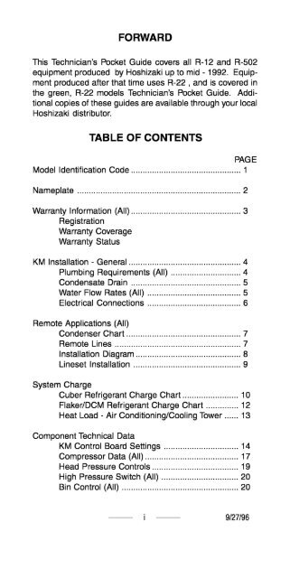
KM Sequence of Operation<br />
“A” & “B” Units . . . . . . . . . . . . . . . . . . . . . . . . . . . . . . . . . . . . . . . . . . . . . . . . . . . . 21<br />
“C” & “Alpine” Units . . . . . . . . . . . . . . . . . . . . . . . . . . . . . . . . . . . . . . . . . . . . 23<br />
KM Check Out Procedure . . . . . . . . . . . . . . . . . . . . . . . . . . . . . . . . . . . . . . . . . . . . . 24<br />
10 Minute Check Out . . . . . . . . . . . . . . . . . . . . . . . . . . . . . . . . . . . . . . . . . 25<br />
Reservior Flush System . . . . . . . . . . . . . . . . . . . . . . . . . . . . . . . . . . . . . 26<br />
Componet Checks<br />
Float Switch . . . . . . . . . . . . . . . . . . . . . . . . . . . . . . . . . . . . . . . . . . . . . . . . . . . . . . . . 27<br />
Thermistor . . . . . . . . . . . . . . . . . . . . . . . . . . . . . . . . . . . . . . . . . . . . . . . . . . . . . . . . . . 27<br />
Control Board . . . . . . . . . . . . . . . . . . . . . . . . . . . . . . . . . . . . . . . . . . . . . . . . . . . . . 28<br />
Bin Control . . . . . . . . . . . . . . . . . . . . . . . . . . . . . . . . . . . . . . . . . . . . . . . . . . . . . . . . . . 28<br />
Cleaning/Sanitizing Procedure . . . . . . . . . . . . . . . . . . . . . . . . . . . . . . . . . . . . . . 30<br />
KM Production Check . . . . . . . . . . . . . . . . . . . . . . . . . . . . . . . . . . . . . . . . . . . . . . . . . . . . 31<br />
Water and Refrigeration Circuit Reference Chart ......... 32<br />
KM Performance Data (R-502 Units)<br />
KM-250B-B ......................................................... 47<br />
KM-250B_C ......................................................... 48<br />
KM-250M-B ........................................................ 49<br />
KM-451 D ............................................................. 50<br />
KM-452D ............................................................. 51<br />
KM-450M-B ........................................................ 52<br />
KM-601 D ............................................................. 53<br />
KM-631 D ............................................................. 54<br />
KM-632D ............................................................. 55<br />
KM-630M-B ........................................................ 56<br />
KM-800M-B ........................................................ 57<br />
KM-l 201 D ........................................................... 58<br />
KM-l 200M-B ...................................................... 59<br />
KM-l 200S_B ....................................................... 60<br />
KM-l 600M-B ...................................................... 61<br />
KM-l 600M-B3 .................................................... 62<br />
KM-l 600S_B ....................................................... 63<br />
KM-l 600S_B3 ..................................................... 64<br />
KM-2000S_B3 ..................................................... 65<br />
NOTE: Performance Data Chart includes the following:<br />
A. Model<br />
B. Supply Voltage<br />
C. Total Amperage (Compressor RLA*)<br />
D. Ice production per cycle<br />
E. Water cooled condenser water consumption<br />
. Production 24 hours<br />
ii ~ g/27/96
G. Freeze cycle time<br />
H. Harvest cycle time<br />
I. High side pressure<br />
J. Suction pressure<br />
*Amperage taken 5 minutes into freeze with<br />
air temperature 104°F and water temperature 80°F.<br />
KM Wiring Diagram Reference Chart . . . . . . . . . . . . . . . . . . . . . . . . . . . 66<br />
Remote Condenser Data ,............................................m 69<br />
Flake lr/DCM<br />
Installation - General . . . . . . . . . . . . . . . . . . . . . . . . . . . . . . . . . . . . . . . . . . . 99<br />
Componant Technical Data .......................................... 99<br />
Gear Motor Safeties ............................................ 99<br />
Auger Bearings ................................................... 99<br />
Bearing Inspection .................................. .......... 100<br />
Auger Inspection / Bearing Replacement.. ....... 100<br />
Flaker Sequence of Operation<br />
Flaker Periodic Flush . . . . . . . . . . . . . . . . . . . . . . . . . . . . . . . . . . . . . . . . 102<br />
DCM Sequence of Operation ........................... .......... 103<br />
F/DCM Production Check ................................. .......... 103<br />
Water and Refrigeration Circuit<br />
Reference Chart . . ..,........................................... 104<br />
Flaker Performance Data<br />
F-251 B ............................................................... 115<br />
F-251 U, F-250B ................................................. 116<br />
F-441 U, F-440B ................................................. 117<br />
F-450B ............................................................... 118<br />
F-450B w/ Cubelet Kit ............................. .......... 119<br />
F-650M .............................................................. 120<br />
F-650M w/ Cubelet Kit ............................ .......... 121<br />
F-l OOOM ............................................................ 122<br />
F-l IOIA ............................................................. 123<br />
F-l 100 w/ Cubelet Kit ............................ .......... 124<br />
F-l 1 OOM ............................................................ 125<br />
F-2000M ............................................................ 126<br />
F-2000M3 .......................................................... 127<br />
. . .<br />
III ~ g/27/96
DCM Performance Data<br />
DCM-231 U, DCM241 U ...................................... 128<br />
DCM-240 BAA, BAB ......................................... 128<br />
DCM-451 U, DCM-450B ..................................... 129<br />
DCM-701 U, DCM-700B ..................................... 130<br />
DCM Wiring Diagram Reference Chart . . . . . . . . . . . . . . . . . . . . . . 131<br />
Flaker Wiring Diagram Referance Chart . . . . . . . . . . . . . . . . . . . . 132<br />
iv ~ g/27/96
IDENTIFICATION CODE<br />
KM - 12<br />
UNITTYPE -r -<br />
KM - Crescent Cuber<br />
F- Flaker<br />
DCM - Dispenser Cubelet Maker<br />
DB - Dispenser Bin<br />
B- Bin<br />
DM - Countertop Dispenser<br />
PRODUCTION<br />
Approximate production/24 Hours<br />
70°F Air/SO”F Water<br />
UNIT STYLE<br />
M/D/A- Modular<br />
S- Stackable<br />
B- Self contained with bin<br />
CONDENSER STYLE<br />
AN- Air cooled<br />
W- Water cooled<br />
R/S - Remote air cooled<br />
GENERATION<br />
IO F<br />
- -<br />
Model designation<br />
U - US Model Designation (First Production)<br />
. - I<br />
The model number, serial number, electrical specifications<br />
and refrigerant data are found on the unit name plate. (See<br />
name plate)<br />
-I- g/27/96
See the Nameplate for electrical and refrigeration specifica-<br />
tions.This Nameplate is located on the upper right hand side<br />
of rear panel. Since this Nameplate is located on the rear<br />
panel of the icemaker, it cannot be read when the back of the<br />
icemaker is against a wall or against another piece of kitchen<br />
equipment. Therefore, the necessary electrical and refrig-<br />
eration information is also on the rating label included on<br />
later model units. This label can be easily seen by removing<br />
only the front panel of the icemaker. We reserve the right to<br />
make changes in specifications and design without prior no-<br />
tice. (Nameplate may vary slightly with older models)<br />
-2p g/27/96
REGISTRATION-<br />
Two warranty registration cards are supplied with the<br />
equipment. They must be completed and sent in to initiate<br />
warranty. The warranty begins on the date of installation if<br />
registration procedures are followed. If registration is not<br />
completed, the warranty date will be the date of sale or<br />
date of shipment from the factory, respectively.<br />
WARRANTY COVERAGE-<br />
The warranty will cover defects in material or workmanship<br />
under normal and proper use and maintenance service as<br />
specified by <strong>Hoshizaki</strong>. Coverage for parts and labor is<br />
limited to the repair or replacement of parts or assemblies<br />
that in <strong>Hoshizaki</strong>’s opinion are defective.<br />
WARRANTY STATUS-<br />
The warranty coverage for R-502 / R-l 2 equipment varies<br />
depending on the model and date of manufacture. Refer to<br />
the warranty statement shipped with the unit to establish<br />
the warranty coverage for that model.<br />
If you need warranty status for later model units, contact<br />
the Care Department with complete model and serial<br />
number. We will provide you with the installation date and<br />
warranty status , if available. You will find the model and<br />
serial number on the nameplate located on the rear of the<br />
unit. Early model units will have the serial number<br />
stamped in ink in the compressor compartment.<br />
See Warranty Statement supplied with the unit for details.<br />
Warranty valid in United States, Canada, Mexico, Puerto<br />
Rico, and U. S. Virgin Islands.<br />
Contact factory<br />
or possessions.<br />
for warranty in other countries, territories,<br />
-3- g/27/96
KM INSTALLATION<br />
GENERAL -<br />
The ice machine is not intended for outdoor use.<br />
OPERATING CONDITIONS - ALL MODELS<br />
ITEM<br />
Voltage Range<br />
MODEL RANGE<br />
115V units 104- 127V.<br />
208-230 V units 187-264V.<br />
Ambient Temperature All 45 - 100 Deg. F.<br />
Remote Condenser Early -20 - 110 Deg. F.<br />
Later -20 - 122 Deg F.<br />
Water SupplyTemperature All 45 - 90 Deg. F.<br />
Water Supply Pressure Early 7 -113 PSIG<br />
Later 10 - 113 PSIG<br />
Allow 6” clearance at rear, sides, and top for proper air<br />
circulation and ease of maintenance or service. 20” top<br />
clearance for F/DCM.<br />
PLUMBING REQUIREMENTS -<br />
Water Supply:<br />
On KM units the water supply line size is critical due to the<br />
water assisted harvest and the use of a ported inlet water<br />
valve solenoid.<br />
MODEL Line Size<br />
KM-250 - KM-800 318” OD<br />
KM-1200 - KM-2000 l/2” OD<br />
All F/DCM 318” OD<br />
*Water cooled condenser units require<br />
supplies sized as per list above.<br />
Fittinq Size<br />
l/2” FPT<br />
l/2” FPT<br />
l/2” FPT<br />
two separate<br />
Drain:<br />
MODEL Line Size Fittinq Size<br />
All Bins 3/4” OD 3/4” FPT<br />
Early KM’s 3/4” OD I” FPT<br />
Later KM’s 3/4” OD 3/4” FPT<br />
**FIakers 3/4” OD 3/4” FPT*<br />
**DCM 3/4” OD 3/4” FPT*<br />
*Some models have 2 drain outlets.<br />
** Some early models had insert type drain fitings<br />
-4- 9127196
<strong>Hoshizaki</strong> recommends that the ice machine drain and bin<br />
drain be piped separately to the drain connection point<br />
allowing ii4” per foot fall.<br />
CONDENSATE DRAIN -<br />
The condensate drain is generally connected to the ice<br />
machine drain for simplicity. It can be piped separately to<br />
the drain exit if desired.<br />
A 6” vent tee is recommended as per drawing:<br />
Reservoir /<br />
Drain<br />
FLOW RATES -<br />
Condensate<br />
Drain<br />
The minimum flow rate requirements for <strong>Hoshizaki</strong> ice<br />
maker units are as follows:<br />
KM-250/AI I Flakers 1.05 GPM<br />
KM-451 /452/450 1.58 GPM<br />
KM-601/631/630/800/Ail DCM’s 2.11 GPM<br />
KM-l 200/l 600 3.96 GPM<br />
KM-1201/2000 4.23 GPM<br />
Use this information when sizing a filter system for the ice<br />
machine application.<br />
NOTE: A good rule of thumb is to utilize a 3 GPM flow rate<br />
filter for KM-250 - 800 and a 5 GPM flow rate filter for KM-<br />
1200 or larger.<br />
-5- g/27/96
ELECTRICAL CONNECTIONS -<br />
115V.<br />
(2 wire<br />
w/gnd)<br />
115VOLT/l PHASE<br />
(Ground<br />
screw not<br />
used on early<br />
models)<br />
208=23OVOLT/l PHASE<br />
208-23OV/l Phase units require a dedicated neutral due to<br />
the use of 115V components.<br />
208-230V.<br />
3 phase<br />
(3 wire<br />
w/gnd)<br />
The dedicated<br />
neutral<br />
requires an<br />
insulated<br />
conductor<br />
which runs<br />
directly to the<br />
panel.<br />
If high leg is present connect to black wire<br />
-<br />
208-230 VOLT/3 PHASE<br />
REMOTE CONDENSER CONNECTIONS<br />
Fan<br />
Control<br />
Circut<br />
From<br />
Unit<br />
115V.<br />
Neutral<br />
GND+@<br />
(Remote<br />
wiring color<br />
varies on<br />
early<br />
models)<br />
9127196
REMOTE APPLICATIONS<br />
CONDENSER CHART<br />
CONDENSER MODEL MODEL NUMBERS<br />
S-0466 KM-601/631 DSU<br />
s-0454 KM-l 201 DSU<br />
S-0387 F-l IOIASU<br />
U RC-4A KM-452DSU, KM-450MRB<br />
U RC-GA/B KM-632DSU, KM-630MRB,<br />
F-l 000/l 1 OOMRB<br />
URC-12B/C KM-800/l 200MRB,<br />
KM1 200SRB<br />
U RC-20C KM-l 600/2000MRB,<br />
KM1 600/2OOOSRB<br />
F-2000MRB<br />
When installing a remote application the unit/condenser<br />
combination must match with the above chart. A non-OEM<br />
multi-pass condenser can be used with prior written factory<br />
approval.<br />
REMOTE LINES-<br />
<strong>Hoshizaki</strong> has 3 precharged line set lengths. 20 foot, 35<br />
foot, and 55 foot sets are available. The line sets are<br />
available in different line sizes for different models.<br />
LINE SET IDENTIFICATION CODE<br />
R502 - 35 6 10<br />
Refrigerant m<br />
Length In Feet<br />
Liquid Line Size in 16th’s<br />
Discharge Line Size in 16th’s<br />
LINE SET APPLICATIONS<br />
MODELS<br />
KM-452/450/631/<br />
LINE SET LL (SIZE] DL<br />
632/630 R502--46-2 l/4” OD 3/8” OD<br />
F-l 000/l 100 R502--46-2 l/4” OD 3/8” OD<br />
KM-l 201 R502--66-2 3/8” OD 3/8” OD<br />
KM-800/l 200 R502--68-2 3/8” OD l/2” OD<br />
KM-l 600/2000 R502--610 3/8” OD 5/8” OD<br />
-7- 9127196
Remote Condenser Installation on Roof<br />
For best<br />
performance<br />
allow 24”<br />
clearance for<br />
air circulation<br />
For best perfor-<br />
mance the Remote<br />
Condenser should<br />
not be more then<br />
33’ above the<br />
icemaker or more<br />
then 10’ below it.<br />
These distances<br />
are measured from<br />
or Connection<br />
..........................................<br />
.........................................<br />
-8- 9127196
LINE SET INSTALLATION<br />
A universal line set adapter kit, part number OS-QUICK, is<br />
available if you need to field engineer your line set. Both<br />
lines should be insulated separately the entire length of<br />
run.<br />
The refrigerant charge for a new unit is distributed between<br />
the unit head and the remote condenser. The line set has a<br />
minimal holding charge of 15 to 30 psig refrigerant vapor.<br />
If you need to field engineer your line set or shorten/<br />
lengthen a precharged line set you can do so by following<br />
these steps:<br />
1. Using the OS-QUICK kit, braze the line set connec-<br />
tions. (If you shorten or lengthen a precharged line<br />
set, recover the holding charge, cut or lengthen and<br />
braze the connections.)<br />
2. Pressurize the lines and leak check all braze joints.<br />
3. Evacuate the lines through the service<br />
Aeroquip quick connect fittings.<br />
ports on the<br />
4. Charge both lines with 15 to 30 psig R-22 vapor.<br />
To make Aeroquip connection to the unit head and<br />
condenser:<br />
1. Lubricate the th reads and O-ring with clean<br />
refrigerant oil.<br />
2. Tighten the female connector until it bottoms out.<br />
3. Then turn an additional l/4 turn to assure a good<br />
brass to brass seal. Leak check the joints with soap<br />
bubbles or an electronic leak detector.<br />
-9- g/27/96
SYSTEM CHARGE<br />
The ice machine head and remote condenser are shipped<br />
with enough refrigerant charge for up to 66 feet of line set<br />
length. The maximum line set length is 100 equivalent feet<br />
from the head to the condenser.<br />
For applications longer than 66 ft. up to the maximum 100<br />
ft. length, additional refrigerant must be added. For units<br />
utilizing l/4” L.L. and 3/8” D.L., the line size should be<br />
increased to 3/8”L.L. and U2”D.L. for the entire length of<br />
the run. Add 21 ounces plus l/2 oz. per foot over 66 feet.<br />
For units utilizing 3/8”L.L., add l/2 oz. per foot over 66 feet.<br />
NOTE:<br />
(1)<br />
(2)<br />
(3)<br />
(4)<br />
(5)<br />
Recommended line sizes are same as listed in the<br />
line set application chart. (Page 7)<br />
Always check the unit nameplate for the<br />
correct refrigerant type.<br />
If refrigerant is added due to extended line set<br />
length, mark the correct total charge on the unit<br />
nameplate for future reference.<br />
When routing and installing remote lines, always<br />
use standard refrigerant piping practices.<br />
<strong>Hoshizaki</strong> recommends eliminating any excess<br />
loops in a pre-charged line set application before<br />
making the unit connections. This will eliminate oil<br />
traps and possible crimps in the excess tubing.<br />
The total system charge is critical for proper operation<br />
according to <strong>Hoshizaki</strong> specification. Always weigh in the<br />
proper charge per the following charge chart. (Remote<br />
units show standard charge good for up to 66 feet.)<br />
~ IO ~ g/27/96
MODEL<br />
HOSHIZAKI CUBER<br />
REFRIGERANT CHARGE CHART<br />
KM-250 BAB<br />
BWB<br />
KM-250 BAC<br />
BWC<br />
KM-250 MAB<br />
MWB<br />
KM-451 DU<br />
DWU<br />
KM-452 DU<br />
DWU<br />
DSU<br />
KM-450 MAB<br />
MWB<br />
MRB<br />
KM-601 DU<br />
DWU<br />
KM-632 DU<br />
DWU<br />
DSU<br />
KM-630 MAB<br />
MWB<br />
MRB<br />
KM-800 MAB<br />
MWB<br />
MRB<br />
KM-1201 DU<br />
DWU<br />
DSU<br />
KM-l 200 MAB<br />
MWB<br />
MRB<br />
KM1200 SAB<br />
SWB<br />
SRB<br />
KM-l 600 M/SWB<br />
M/SRB<br />
KM-2000 M/SWB<br />
M/SRB<br />
TOTAL CHARGE REFRIGERANT<br />
1 lb. 5 oz. R-502<br />
13.5 oz. LL<br />
13.8 oz. LL<br />
13.4 oz. LL<br />
1 lb. 13.5 oz. LL<br />
1 lb. 12.5 oz. LL<br />
1 lb. 9 oz. LL<br />
1 lb. 3 oz. LL<br />
1 lb. 10 oz. LL<br />
1 lb. 3 oz. LL<br />
5 Ibs. 5 oz. LL<br />
1 lb. 10 oz. LL<br />
1 lb. 1 oz. LL<br />
5 Ibs. 5 oz. LL<br />
2 Ibs. 3 oz. LL<br />
1 lb. 5 oz. LL<br />
2 Ibs. 3 oz. LL<br />
1 lb. 7 oz. LL<br />
5 Ibs. 12 oz. LL<br />
2 Ibs. 3 oz. LL<br />
1 Ibs. 8 oz. LL<br />
5 Ibs. 12 oz. LL<br />
3 Ibs. 1 oz. LL<br />
2 Ibs. 3 oz. LL<br />
8 Ibs. 13 oz. LL<br />
4 Ibs. LL<br />
2 lb. 7 oz. LL<br />
11 Ibs. 1 oz. LL<br />
4 Ibs. 6 oz. LL<br />
2 Ibs. 1 oz. LL<br />
11 Ibs. 11 oz. LL<br />
4 Ibs. 6 oz. LL<br />
2 Ibs. LL<br />
12 Ibs. 2 oz. LL<br />
2 Ibs. 14 oz. LL<br />
17 Ibs. 10 oz. LL<br />
3 Ibs. 12 oz. LL<br />
17 Ibs. 10 oz. LL<br />
g/27/96
MODEL<br />
F-251 B<br />
F-251 U<br />
F-250 BAA<br />
F-441 U<br />
F-440 BAA<br />
F-450 BAB<br />
BWB<br />
F-650 MAB<br />
MWB<br />
MRB<br />
F-l 000 MAB<br />
MWB<br />
MRB<br />
F-1101 AU<br />
AWU<br />
ASU<br />
F-l 100 MAB<br />
MWB<br />
MRB<br />
F-2000 MWB<br />
MRB<br />
DCM-231 U<br />
DCM-241 U<br />
DCM-451 U<br />
HOSHIZAKI FLAKERWDCM’S<br />
REFRIGERANT CHARGE CHART<br />
TOTAL CHARGE<br />
6.3 oz.<br />
7.76 oz.<br />
7.76 oz.<br />
13.4 oz.<br />
13.4 oz.<br />
1 lb.<br />
12.70~.<br />
1 lb. 9 oz.<br />
12.7 oz.<br />
4 Ibs.<br />
1 Ibs.<br />
1 lb.<br />
6 Ibs.<br />
1 Ibs.<br />
1 Ibs.<br />
5 Ibs.<br />
1 lb.<br />
1 lb.<br />
5 Ibs.<br />
1 lb.<br />
15 Ibs.<br />
14 oz.<br />
10 oz.<br />
12 oz.<br />
2 oz.<br />
1 oz.<br />
8 oz.<br />
loz.<br />
8 oz.<br />
1 loz.<br />
10 oz.<br />
7.5 oz.<br />
8.8 oz.<br />
14.1 oz.<br />
REFRIGERANT<br />
R-12<br />
R-12<br />
R-12<br />
R-12<br />
R-12<br />
R-502<br />
R-502<br />
R-502<br />
R-502<br />
R-502<br />
R-502<br />
R-502<br />
R-502<br />
R-502<br />
R-502<br />
R-502<br />
R-502<br />
R-502<br />
R-502<br />
R-502<br />
R-502<br />
R-12<br />
R-12<br />
R-12<br />
DCM-450 BAAIBAB 14.1 oz. R-12<br />
DCM-450 BWA/BWB 10.6 oz. R-12<br />
DCM-701 U 1 lb. 12.2 oz. R-502<br />
DCM-701 WU 1 lb. 6.9 oz. R-502<br />
DCM-700 BAA/BAB 1 lb. 12.2 oz. R-502<br />
DCM-700 BWA/BWB 1 lb. 6.9 oz. R-502<br />
~ 12 ~ g/27/96
HEAT LOAD<br />
The heat of rejection information listed below by model<br />
number should be used for sizing air conditioning equip-<br />
ment or for sizing a water cooled cooling tower application.<br />
MODEL<br />
KM-250B<br />
KM-250M<br />
KM-451 D<br />
KM-452D<br />
KM-450M<br />
KM-601 / 631 D<br />
KM-632D<br />
KM-630M<br />
KM-800M<br />
KM-l 201 D<br />
KM-l 200M<br />
KM-l 200s<br />
KM-l 600M/S<br />
KM-2000M/S<br />
MODEL<br />
F-251 B<br />
F-251 U<br />
F-250 B-A<br />
F-441 U<br />
F-440 B-A<br />
F-450 B-B<br />
F-650 M-B<br />
F-l 000 M-B<br />
F-1101 A-<br />
F-l 100 M-A<br />
F-2000 M-B<br />
DCM-231/241 U<br />
DCM-240 B<br />
DCM-451 U<br />
DCM-450 B<br />
DCM-701 U<br />
DCM-700 B<br />
TOTAL HEAT REJECTION<br />
AIR WATER COOLED<br />
COOLED (CONDENSER ONLY]<br />
5443 BTU/h 5245 BTU/h<br />
5450 5250<br />
10319 8500<br />
9220 8047<br />
9250 6160<br />
11509 9520<br />
12713 11817<br />
12713 10985<br />
16960 12700<br />
20300 16500<br />
19500 17000<br />
20550 17370<br />
-------- 24393<br />
-------- 28120<br />
TOTAL HEAT REJECTION<br />
AIR WATER COOLED<br />
COOLED (CONDENSER ONLY]<br />
3170 BTU/h ------ BTU/h<br />
2614 ------<br />
3980 ------<br />
6030 ------<br />
6030 ------<br />
5000 2860<br />
6830 5546<br />
8480 6700<br />
10600 8990<br />
10800 9500<br />
--- 18100<br />
3040 ------<br />
3980 ------<br />
5680 5160<br />
5680 5160<br />
8440 6620<br />
8440 6690<br />
Figures shown are at 90” F air temp. 70” F water temp.<br />
Allow for a pressure drop of 7 psi across the water cooled<br />
condenser.<br />
~ 13 ~ g/27/96
KM-451/601/631/1201 First Generation<br />
(unit starts in harvest)<br />
The first generation of KM cubers used an “A” style control<br />
board. This board has a variable resistor in the upper right<br />
hand corner marked VRI. To adjust the defrost completion<br />
timer and extend the harvest period, turn VRI “CW”. The<br />
range extends from 1 to 4 minutes. Fully “CCW” provides<br />
1 minute on the completion timer. Extending the harvest<br />
will increase the flush for more cleaning. The factory<br />
setting is 1 minute (fully CCW).<br />
KM-451/ 631/1201 Second Generation<br />
(unit starts in harvest)<br />
The control board on the second generation of KM cubers<br />
was changed to a “B” style. This board uses two dip<br />
switches to adjust the defrost completion timer. A dip<br />
switch setting chart is printed on the board, beside the<br />
switches. Adjust the two switches to extend the harvest<br />
period from 1 to 4 minutes. This board also has a 60<br />
minute back-up freeze completion timer and a high<br />
temperature safety included. The factory setting is 1<br />
minute. The “B” style board is a direct replacement for the<br />
“A” board.<br />
KM-452/632/ early M & S units Third Generation<br />
(unit starts in 1 minute fill cycle and has every cycle pump-out)<br />
The third generation control board for the KM cubers is a<br />
“C” style board. This board has 4 dip switches. Number 1<br />
& 2 adjust the defrost completion timer from 1 to 3 minutes.<br />
Number 3 & 4 adjust the length of pump-out and should<br />
remain in the factory position. The pump-out will occur<br />
after every harvest cycle on these units. For the factory<br />
setting, see the dip switch setting chart for Alpine boards.<br />
The “C” board replacement is the Universal Alpine #<br />
2UO139-01. This is a direct replacement. Install the<br />
universal board and adjust the 8 dip switches by model per<br />
the dip switch setting chart. “C” board switches 1 through 4<br />
are the same as on the Alpine board.<br />
KM later model M & S units Forth Generation<br />
(unit starts in 1 minute fill cycle and has every cycle pump-out)<br />
All KM Units are now manufactured with the original Alpine<br />
control board part # 2UO127-01 (subs to # SAOOOI). This<br />
board has 8 dip switches and provides the ability to adjust<br />
~ 14 ~ g/27/96
for pump-out to occur every 1, 2, 5, or 10 cycles. The<br />
setting guide below explains the Original and Universal<br />
Alpine dip switches.<br />
Note: The Universal Alpine # 2UOO139-01 can be used to<br />
replace the Original Alpine # 2UO127-01 if a slight<br />
modification is made. Follow the instructions supplied<br />
with the replacement board which instruct you to cut the<br />
black jumped (R065) for this application.<br />
DIP SWITCH SE<br />
ADJUSTMENTS DIP<br />
DEFROST<br />
TIMER<br />
ADJUSTMENT<br />
PUMP OUT 3<br />
LENGTH 4<br />
PERIODIC<br />
PUMP OUT<br />
FREQUENCY<br />
0 1 0 1<br />
0 0 1 1<br />
seconds 10 10 10 20<br />
5 0 1 0 1<br />
6 0 0 1 1<br />
TEST 8 OFF FOR TEST<br />
Switch Code =ON O=Off<br />
glF II2 II5 l/IO 1<br />
I/VSTRUCTIO/VS:<br />
TO IMPROVE BUILT-IN CLEANING Adjust switches<br />
per this guide. Switches 1 & 2 provide for longer flush<br />
at the end of harvest. Switches 5 & 6 provide<br />
maximum cleaning at every cycle 1 / 1 setting. The 1 /<br />
10 setting will pump-out less to conserve water (less<br />
cleaning).<br />
DO NOT ADJUST SWITCHES 3,4,7, & 8 FROM<br />
THE FACTORY SETTINGS !<br />
DO NOT MAKE CONNECTIONTOTHE RED K-4<br />
TERMINAL !<br />
The replacement board should be adjusted to the<br />
factory settings unless local conditions require<br />
alternate settings to improve cleaning.<br />
~ 15 ~ g/27/96
g/27/96<br />
000000000<br />
ooooo----<br />
Orn<br />
3<br />
><br />
ooo-o---ooo-o----<br />
-I<br />
7<br />
-7-700000<br />
-7-700000<br />
0<br />
0<br />
000000000<br />
000000000
- 17<br />
I I g/27/96
9127196
WATER COOLED<br />
HEAD PRESSURE CONTROLS<br />
An adjustable (Pressure Modulated) water regulating valve<br />
is installed on the water cooled condenser outlet. Adjust<br />
the valve per this diagram to reflect the outlet temperature<br />
in the chart below.<br />
ADJUSTMENT SCREW Adjust:<br />
TOP VIEW<br />
CW - for higher<br />
pressure and outlet<br />
water temperature,<br />
lower water flow.<br />
CCW - for lower<br />
pressure and outlet<br />
water temperature,<br />
higher water flow.<br />
CONDENSER OUTLET WATER TEMPERATURE RANGE<br />
Model Ranqe (F”) Model Ranqe (F”)<br />
KM-250BWB / 100 - 104 KM-1201DWU 110 - 115<br />
BWC / MWC<br />
KM-451 DWU , 100 - 104 KM-1200 MWB 100 - 104<br />
KM-450 MWB<br />
KM-601/631/ 100 - 104 KM-1200 SWB 108 - 113<br />
632DWU<br />
KM-630 MWB 100 - 104 KM-1600 MWB 104 - 115<br />
KM-800 MWB 102 - 108 KM-1600 SWB 104 - 115<br />
KM-2000 SWB 104 - 115 All Flaker / DCM 100 - 104<br />
REMOTE<br />
All remote condenser units use a condenser pressure<br />
regulator ( CPR or Headmaster ) to maintain adequate<br />
head pressure in low ambient conditions. This valve is<br />
located in the remote condenser unit. The replacement<br />
valve is a Sporlan 190 psi LAC-4 valve <strong>Hoshizaki</strong> part<br />
number 440918-01. This valve can be used on any remote<br />
R-502 unit.<br />
The symptoms of a bad headmaster are similar to an<br />
undercharged unit. To diagnose a headmaster, add<br />
~ 19 ~ g/27/96
additional refrigerant in 2 lb. increments and watch the<br />
pressures. If the pressures begin to look normal, the unit<br />
was undercharged. If not, a bad headmaster is a possibil-<br />
ity. Check to see if the valve is stuck open or closed by<br />
conducting temperature test at the outlet of the headmas-<br />
ter.<br />
Always use safe refrigeration practices<br />
valve and protect from overheating.<br />
HIGH PRESSURE SAFETY SWITCH -<br />
when removing the<br />
An automatic reset high pressure safety switch is used on<br />
some Flakers and DCM’s, and on all KM series units. The<br />
pressure switch settings are as follows:<br />
MODELS PART NUMBER CUT OUT CUT IN<br />
(psig) (psig)<br />
F-441U , DCM-451U DCM-450B<br />
3110069-03 228 +I- 21.3 185 +I- 21.3<br />
KM-451 D ,<br />
KM-l 201 D<br />
-B/M/S<br />
KM-6OIU , KM-63<br />
3110069-01<br />
3110069-04<br />
AIR COOLED<br />
43344 I-05<br />
1 D , DCM-70<br />
356 +I- 21.3<br />
356 +I- 21.3<br />
& REMOTE<br />
384 +I- 21.3<br />
IU<br />
, DCM-700B<br />
256 +I- 21.3<br />
256 +I- 21.3<br />
284 +I- 21.3<br />
KM-B / M / S WATER COOLED, F-450B , F-650M ,<br />
FIOOOM , F-2000M<br />
433441-01 355.6 +I- 21.3 256 +I- 21.3<br />
F-IIOIA , F-l 1 OOM<br />
4256 79-01 356 +I- 21.3 296 +/- 21.3<br />
BIN CONTROL<br />
KM series units use a thermostatic bin control. The<br />
capillary bulb is mounted in the ice drop zone or on a drop<br />
down bracket which extends into the bin cavity. The drop<br />
down bracket should be secured to the unit base and plug<br />
connection must be made before the unit will operate.<br />
When replacing a thermostatic bin control, be sure to use<br />
the ABS mounting hardware supplied with the new control.<br />
~ 20 ~ g/27/96
Check the operation of the bin control by holding ice<br />
against the thermostatic bulb with the unit running. The<br />
unit should shut down within 6 to 10 seconds. Adjust the<br />
control “CCW ” for a faster shut down. If the bin control<br />
bulb is not contacting the ice pyramid, a bracket extention<br />
may be needed.<br />
Flaker / DCM units use mechanical bin controls. A paddle<br />
pivots on a hinge pin to operate either a microswitch or<br />
magnetic proximity switch. For proper operation, assure<br />
that the paddle swings freely.<br />
CAPACITORS<br />
See wiring diagram reference chart for capacitor ratings.<br />
HOSHIZAKI KM CUBER SEQUENCE<br />
OF OPERATION FOR “A” & “B”<br />
CONTROL BOARD UNITS<br />
1. Harvest Cycle<br />
The unit always starts in the ha ,rvest cycle. When the<br />
power switch is set to the “ICE” position and the bin<br />
control is closed (calling for ice) the harvest cycle<br />
begins. The compressor and remote fan motor starts,<br />
the hot gas valve opens, and the inlet water valve(s)<br />
opens. This is a hot gas defrost with water assist. The<br />
water flows through the center of the evaporator, picks<br />
up heat from the serpentine and transfers it to the<br />
stainless freezing surface. When the suction line<br />
temperature reaches 48°F (43°F on KM-120 1) the<br />
thermistor which is mounted to the suction line signals<br />
the board to start the defrost completion timer. This<br />
timer is factory set at 1 minute, however, it can be<br />
adjusted from 1 to 4 minutes.<br />
The total harvest time will be the time it takes for the<br />
evaporator to reach 48°F or 43°F plus the defrost<br />
completion timer setting. Total harvest time will be<br />
longer in the winter due to the colder incoming water<br />
temperature. The inlet water valve will be open a<br />
maximum time of 3 minutes on KM-451/601/631 water<br />
cooled models and 4 minutes on other “A” & “B” board<br />
models or the length of harvest, whichever is less.<br />
~ 21 ~ g/27/96
2.<br />
At the end of every harvest, water overflows the<br />
reservoir stand pipe to flush concentrated minerals<br />
out of the reservoir and down the drain. This<br />
flush can be extended by adjusting the defrost<br />
completion timer to a longer setting. Remember that<br />
this will lengthen the total harvest time.<br />
Freeze Cycle<br />
When the defrost completion timer times out, the<br />
freeze cycle begins. The compressor continues to<br />
operate, the hot gas and inlet water valves close, and<br />
the pump motor and self contained condenser fan<br />
motor starts. For the first five minutes of freeze, a<br />
short cycle protection timer on the board is in control.<br />
After 5 minutes, the control board re-checks the<br />
thermistor for 43°F (38°F for KM-1201). this assures<br />
that the hot gas valve has closed. The float switch now<br />
assumes control of the freeze cycle.<br />
You will notice that the total cycle time for KM units is<br />
up to three times that of other cubers in the market.<br />
This longer cycle is designed into the unit operation.<br />
See the unit performance data by model in this guide<br />
for actual cycle times.<br />
As the water cools and ice forms on the evaporator,<br />
the water level in the reservoir drops. When the level<br />
drops, the float in the float switch drops and finally<br />
opens the circuit. This starts the next harvest cycle<br />
(cycle returns to 1 above). The water level in the<br />
reservoir actually controls the float switch circuit. If the<br />
float is adjusted upwards, the unit will cycle quicker<br />
allowing for a smaller cube size. The unit is shipped<br />
from the factory with the float switch adjusted to the<br />
large cube size. This setting provides the best<br />
efficiency for the KM series units.<br />
FOR FACTORY SUPPORT<br />
co NTACT HOSHIZAKI CARE<br />
1 -800-233-I 940<br />
AT:<br />
~ 22 ~ g/27/96
HOSHIZAKI KM CUBER<br />
SEQUENCE OF OPERATION<br />
For ALL “C” or ALPINE control board units, KM452, 632,<br />
M & S Models<br />
THE STEPS IN THE SEQUENCE ARE AS FOLLOWS:<br />
1. 1 Minute Fill Cycle<br />
The unit always starts in the 1 minute fill cycle. When<br />
power is applied to the unit the water valve is energized<br />
and the fill period begins. After 1 minute the board<br />
checks for a closed float switch. If the float switch is<br />
closed the harvest cycle begins. If not, the unit will not<br />
start without adequate water in the sump. This serves<br />
as a low water safety shut off. The water valve will<br />
remain energized through additional 1 minute cycles<br />
until water enters the sump and the float switch closes.<br />
2. 1st Harvest Cycle<br />
The compressor starts, hot gas valve opens, water<br />
valve remains open and harvest begins. As the<br />
evaporator warms, the thermistor located on the<br />
suction line checks for a 48” F. temperature. When<br />
48” F. is reached, the harvest is turned over to the<br />
adjustable control board defrost timer which is factory<br />
set for normal conditions. This adjustment can vary the<br />
defrost timer from 1 to 3 minutes.<br />
3. Freeze Cycle<br />
After the timer terminates the harvest cycle, the<br />
hot gas and water valves close, and the freeze<br />
cycle starts. For the first 5 minutes the controller<br />
board will not accept a signal from the float switch to<br />
end the freeze cycle. This 5 minute minimum freeze<br />
acts as a short cycle protection. At the end of 5<br />
minutes the float switch assumes control. As ice builds<br />
on the evaporator the water level in the sump lowers.<br />
The freeze continues until the float switch opens and<br />
terminates ice production.<br />
4. Harvest Pump Out<br />
When the float switch opens and signals the<br />
completion of the freeze cycle, the harvest cycle<br />
begins. The hot gas valve opens and the compressor<br />
~ 23 ~ g/27/96
continues to run. The d rain<br />
IO/20 second pump ou t.<br />
starts counting the<br />
The water pump stops for 2 seconds and reverses,<br />
taking water from the bottom of the sump and forcing<br />
pressure against the check valve seat allowing water to<br />
go through the check valve and down the drain. At the<br />
same time water flows through the small tube to power<br />
flush the float switch. When the drain timer stops<br />
counting, the pump out is complete.<br />
Pump out always occurs on the 2nd harvest after<br />
startup. The Alpine control board allows for adjustment<br />
for pump out to occur every cycle, or every 2nd, 5th or<br />
10th cycle from this point.<br />
5. Normal Harvest Cycle<br />
The water valve opens to allow water to assist the<br />
harvest. As the evaporator warms, the thermistor<br />
reaches 48” F. The control board receives the<br />
thermistor signal and starts the defrost timer. The water<br />
valve is open during harvest (defrost) for a maximum of<br />
6 minutes or the length of harvest, whichever is shorter.<br />
When the defrost timer completes its count down, the<br />
defrost cycle is complete and the next freeze cycle<br />
starts.<br />
The unit continues through 3, 4 and 5 sequence until<br />
the bin control senses ice and shuts the unit down.<br />
KM CHECK OUT PROCEDURE<br />
The 10 minute check out procedure is basically a<br />
sequence check which can be used at unit start up or for<br />
system diagnosis. Using this check out procedure will allow<br />
you to diagnose electrical system and component failures<br />
in approximately 10 minutes under normal operating<br />
conditions of 70°F or warmer air and 50°F or warmer water<br />
temperatures. Before conducting a 10 minute check out,<br />
check for correct installation, proper voltage per unit name<br />
plate and adequate water supply. As you go through the<br />
procedure, check to assure the components energize and<br />
de-energize correctly. If not, those components and<br />
controls are suspect.<br />
~ 24 ~ 9127196
10 MINUTE CHECK OUT PROCEDURE<br />
ALPINE CONTROL BOARD<br />
I-Turn power off-Gain access to control board<br />
2-Turn power on-place control switch in ice position<br />
A) 1 minute fill period-WV energized<br />
After 1 minute control board checks FS. If FS is<br />
closed . . . unit cycles to Harvest. Continue to (B).<br />
If FS is open unit repeats 1 minute fill cycle until<br />
switch closes (low water safety protection during<br />
initial start up and at the end of each harvest.)<br />
B) Initial Harvest Cycle WV remains energized, C,<br />
HGV, (FM on RS model) energize. Evaporator<br />
warms-thermistor senses 48°F turns operation of<br />
harvest to control board defrost completion timer-<br />
timer completes-unit cycles to freeze continue to (C)<br />
* Harvest time varies with water and air temp.<br />
(Average 2-3 minutes). If unit fails to cycle into<br />
freeze, check thermistor and control board.<br />
C) Freeze cycle-C remains energized, PM (LV on RS<br />
model) and FM energized, WV, HGV de-energized.<br />
Unit is locked in freeze by 5 minute short cycle<br />
protection timer. After 5 minutes, freeze cycle<br />
operation is transferred to FS for freeze termina-<br />
tion. During first 5 minutes of freeze, confirm that<br />
evaporator temp. drops. After 7 minutes in freeze,<br />
remove black float switch lead from control board<br />
(K5) terminal . . . unit should immediately switch to<br />
normal Harvest Cycle-continue to (D).<br />
*If unit remains in Freeze after 7 minutes with<br />
FS lead removed, change control board.<br />
D) Normal Harvest Cycle (IO/20 second pump out) C<br />
remains energized, HGV energizes. PM stops for 2<br />
seconds and starts in reverse rotation for 1 O/20<br />
seconds. (This removes contaminants from water<br />
sump through check valve and down the drain and<br />
allows for power flush of FS.) Check clear tubing at<br />
check valve, or unit drain for water flow to affirm<br />
pumpout.<br />
~ 25 ~ g/27/96
E) Normal harvest continues -WV energized- return<br />
to (B).<br />
* Unit continues through sequence (B) . . (C) . .<br />
(D) until bin control is satisfied or power is<br />
turned off.<br />
* Unit starts at (A) any time bin control operates<br />
or power is interrupted.<br />
NOTE: A & B control board check out procedure<br />
requires additional time (approximately 18 minutes total).<br />
Same sequence as above excluding step (A) 1 minute fill<br />
and (D) 1 O/20 second pump out. In step (C) allow 10 to 12<br />
minutes in freeze before removing FS lead.<br />
Legend: C = Compressor LV = Line Valve<br />
CC = Contractor Coil PM = Pump Motor<br />
FM = Condenser Fan Motor RS = Remote System<br />
FS = Float Switch WV = Inlet Water Valve<br />
HGV = Hot Gas Valve<br />
RESERVOIR FLUSH SYSTEM<br />
A displacement device ( cap or assembly ) is positioned<br />
over the top of the overflow stand pipe. This device allows<br />
sediment to be pulled from the bottom of the reservoir and<br />
flush down the drain when overflow occurs. Water should<br />
always overflow the stand pipe for a short period towards<br />
the end of harvest to allow this flushing action. If overflow<br />
does not occur, you have restricted water flow into the unit.<br />
Check the inlet water valve screen , your incoming water<br />
line size or the external filtration system.<br />
Pump out models have a built-in power flush of the float<br />
switch. Models without a pump out will have a white,<br />
gravity flow, flush box mounted inside of the evaporator<br />
compartment. This box has an internal stand pipe with a<br />
siphon cap over it. A small fill tube fills the box with water<br />
from the inlet supply pipe during harvest. When this box<br />
fills completely, it empties due to the siphon effect and<br />
flushes the float tank. If the water valve is leaking by, the<br />
box will fill in freeze and empty into the float. This can<br />
cause premature harvest or a short cycling effect.<br />
~ 26 ~ g/27/96
COMPONENT CHECKS:<br />
1. Check out the float switch with an ohm meter. When the<br />
float is up, the switch is closed. When the float is fully<br />
down, the switch is open. The symptoms of a bad or<br />
sticking float switch are:<br />
Up / Closed: 60 minute freeze cycle (longer for<br />
“A” board units)<br />
Down / Open: “A” or “B” board units will cycle<br />
back to harvest after 5 to 7 minutes<br />
in freeze. “C” or Alpine board units<br />
will shut down on low water safety<br />
(water runs continuously with no<br />
unit operation).<br />
2. The thermistor must be mounted securely to the suction<br />
line using a heat sink compound. This assures good<br />
heat transfer and accurate sensing of the suction line<br />
temperature. Use <strong>Hoshizaki</strong> part number: 4A0683-01 or<br />
equivalent. (Radio Shack #276-1372 or GE Electronics<br />
#I O-81 08)<br />
Check out the thermistor mounting and check thermistor<br />
resistance versus temperature per this chart:<br />
THERMISTOR TEMPERATURE / RESISTANCE<br />
SENSOR TEMP(“F) RESISTANCE (K OHMS)<br />
0 14.4<br />
10<br />
10.6<br />
32<br />
6.0<br />
50 3.9<br />
70 2.5<br />
90 1.6<br />
The symptoms of a bad thermistor are:<br />
Open: Unit remains in harvest for 15 minutes on “C”<br />
board, 20 minutes on Alpine boards.<br />
Unit remains in harvest permanently on “A”<br />
or “B” boards.<br />
Shorted: Unit locks out on manual reset high tempera-<br />
ture safety.<br />
Note: On “B”, “C”, & Alpine boards, if the evaporator<br />
reaches 127°F the thermistor signal (500 ohms) shuts<br />
down the unit on this manual reset safety. This is the only<br />
~ 27 ~ 9127196
manual safety in the KM series units. To safety<br />
turn the unit power off and back on.<br />
3. For “C” or Alpine board units, check out the control<br />
board using a volt meter to check the 12 volt control<br />
voltage at connector K2. On all boards, check for 115<br />
to 120 VAC input and output voltage to each compo-<br />
nent at the Kl connector. High input voltage will shut<br />
down “C” or Alpine units on an automatic reset safety.<br />
Alpine units have a built in automatic reset low voltage<br />
safety also.<br />
4. The bin control used on all KM units is an adjustable,<br />
thermostatic control. The thermostatic bulb is mounted<br />
in the ice drop area. To adjust the bin control, hold ice<br />
against the bulb while the unit is operating. The unit<br />
should shut off within 6 to 10 seconds. If this does not<br />
occur adjust the thermostatic control by turning the<br />
screwdriver slot. Adjusting towards warmer will allow<br />
the unit to shut down quicker. This adjustment should<br />
be checked at installation, when diagnosing a bin<br />
control problem, or if a replacement bin control is<br />
installed.<br />
KM 451 / 631 / 1201 units have a bin control bracket<br />
that mounts under the unit. KM-250M, and all KM-<br />
1200M / S and larger units have a drop down bracket<br />
that must be dropped down, secured, and plugged in<br />
at installation. The ice must contact the bulb to<br />
operate the bin control. Some bin applications<br />
require an extention bracket or relocation of the bulb<br />
mounting to allow for proper shut down. Check this<br />
positioning if the control is adjusted properly and ice<br />
continues to back up into the evaporator section.<br />
The symptom of a bad bin control are:<br />
Stuck closed : The unit continues to operate when<br />
the bin is full. This allows ice to back up in the<br />
evaporator section and generally causes a freeze up<br />
condition. This will also occur if the bin control is<br />
adjusted to cold or fully “CW”. Check the adjustment<br />
and bulb location before you diagnose a stuck bin<br />
control.<br />
~ 28 ~ g/27/96
Stuck open : The unit will not start in the ice position.<br />
An easy method to check for an open bin control on M<br />
& S units is to flip the control switch to wash, if the<br />
pump starts, the bin control is closed. The same check<br />
can be used on KM-451 / 631 / 1201 units however,<br />
they have a 2 minute time delay before the pump starts<br />
if the unit is shut off.<br />
DCM Bin controls may be a mechanical flapper with a<br />
magnetic proximity switch or a micro-switch assembly.<br />
Since these controls have moving parts, make sure<br />
that all parts move freely. Sticking can occur if scale<br />
builds at the pivot points.<br />
Flakers may have either a mechanical or thermostatic<br />
control. In some cases, depending on the model, both<br />
types are combined to provide increased safety. Some<br />
flakers have an additional spout safety control which<br />
will be a thermostatic or mechanical type. This control<br />
may have an audible alarm and has a manual reset.<br />
The spout control backs up the bin control, shuting<br />
down on this manual reset safety. If this occurs, always<br />
check the bin control operation.<br />
5. Check other<br />
multimeter.<br />
components using a good quality<br />
~ 29 ~ g/27/96
A label which details the step by step cleaning/sanitizing<br />
procedure is located on the inside front panel of the ice<br />
machine. These instructions are also provided in the<br />
Instruction Manual shipped with each unit. Follow these<br />
instructions to conduct a thorough cleaning and sanitizing<br />
of the water system.<br />
Annual cleanings are recommended. More frequent<br />
cleanings may be required in bad water areas.<br />
CLEANERS-<br />
<strong>Hoshizaki</strong> recommends “<strong>Hoshizaki</strong> Scale Away’ or “Lime-<br />
A-Way” (by Economics Laboratory, <strong>Inc</strong>.) however any FDA<br />
approved ice machine cleaner is acceptable. If you carry a<br />
nickel safe cleaner, the acidic solution is weaker than<br />
normal cleaners to protect plated surfaces.You may need<br />
to use a heavier mixture of nickel safe to cut heavier scale<br />
deposits.<br />
RECOMMENDED CLEANING SOLUTION MIXTURE<br />
MODEL CLEANER WATER<br />
KM-250 7 FI. Oz.<br />
KM-500/630/800 16 FI. Oz.<br />
KM-l 200/l 600 27 FI. Oz.<br />
KM-2000/2400 38 FI. Oz.<br />
All Flakers / DCM 9.6 FI. Oz.<br />
1.3 Gal.<br />
3.0 Gal.<br />
5.0 Gal.<br />
7.0 Gal.<br />
1.6 Gal.<br />
The system should be sanitized using a solution of water<br />
and 5.25% sodium hypochlorite. Any commercial sanitizer<br />
recommended for ice machine application is acceptable.<br />
RECOMMENDED SANITIZING SOLUTION MIXTURE<br />
MODEL SANITIZER WATER<br />
KM-250<br />
KM-500/630/800<br />
KM-l 200/l 600<br />
KM-2000/2400<br />
All Flakers / DCM<br />
.65 FI. Oz. 1.3 Gal.<br />
1.5 FI. Oz. 3.0 Gal.<br />
2.5 FI. Oz. 5.0 Gal.<br />
3.7 FI. Oz. 7.0 Gal.<br />
2.5 FI. Oz. 5.0 Gal.<br />
~ 30 ~ g/27/96
The steps for a cuber production check are as follows:<br />
1. Time a complete cycle from the beginning of one<br />
freeze cycle to the beginning of the next freeze<br />
cycle.<br />
2. Catch al of the<br />
the total batch.<br />
ice from this freeze cycle and weigh<br />
3. Divide the total minutes in a 24 hour day (1440<br />
minutes) by the complete cycle time in minutes to<br />
obtain the number of cycles per day.<br />
4. Multiply the number of cycles per day by the cycle<br />
batch weigh t for the cuber production per 24 hours.<br />
(1440. Total Cycle Time)<br />
24 Hou r Production<br />
x Ice Weight=<br />
Once you calculate the production, check the incoming<br />
water temperature, and ambient condensing temperature<br />
at the cuber and cross reference to performance data<br />
included in this manual to see if the calculation falls within<br />
10% of the specification.<br />
For the most accurate production check, a normal freeze<br />
cycle should be checked. If the evaporator compartment<br />
has been opened for service or if the unit has been cut off<br />
for a long period of time, the first freeze cycle will be longer<br />
than normal. Timing this cycle can result in an inaccurate<br />
production check. To avoid this, start the unit and allow it to<br />
operate for 10 minutes in the freeze cycle, unplug the float<br />
switch lead and cause the unit to cycle into harvest mode.<br />
Replug the float switch and start timing as soon as the next<br />
freeze begins. Also remember that the evaporator<br />
compartment must be closed during the production check.<br />
Removing the front cover to check the ice buildup during a<br />
production check will allow heat into the evaporator and will<br />
affect the total cycle time and actual production.<br />
~ 31 ~ g/27/96
WATER AND REFRIGERATION CIRCUIT<br />
DRAWING REFERENCE CHART<br />
MODEL PAGE<br />
KM-250B .................................................................... 33<br />
KM-250M ................................................................... 34<br />
KM-451 DU ................................................................. 35<br />
KM-451 DWU .............................................................. 36<br />
KM-452DU, DWU ....................................................... 40<br />
KM-450MAB, MWB ................................................... 40<br />
KM-450MRB .............................................................. 41<br />
KM-601 D .................................................................... 36<br />
KM-631 DU, DWU ....................................................... 36<br />
KM-631 DSU ............................................................... 37<br />
KM-632DU, DWU ....................................................... 40<br />
KM-632DSU ............................................................... 41<br />
KM-630MAB, MWB ................................................... 40<br />
KM-630MRB .............................................................. 41<br />
KM-800MAB, MWB ................................................... 40<br />
KM-800MRB .............................................................. 41<br />
KM-l 201 DWU ............................................................ 38<br />
KM-l 201 DU, DSU ..................................................... 39<br />
KM-l 200MAB, MWB ................................................. 42<br />
KM-1200MRB ............................................................ 43<br />
KM-1200SAB, SWB ................................................... 44<br />
KM1 200SRB .............................................................. 45<br />
KM-l GOOMRB ............................................................ 43<br />
KM1 600SWB ............................................................. 44<br />
KM1 GOOSRB .............................................................. 45<br />
KM2000SWB, SRB .................................................... 46<br />
NOTE: Some drawings have been combined to represent<br />
more than one model.<br />
g/27/96
KM=250BAB, KM-250BWB<br />
KM=250BAC, KM-250BWC<br />
~ 33 ~ g/27/96
KM=250MAB, KM-250MWB<br />
Water<br />
/==<br />
g/27/96
**stw<br />
%PFl,<br />
-<br />
KM-451 DU<br />
~ 35 ~ 9127196
KM-451 DWU<br />
KM-601 DU, KM-601 DWU<br />
KM-631 DU, KM-631 DWU<br />
g/27/96
KM-631 DSU<br />
\.-.<br />
~ 37 ~ 9127196
KM-1201 DWU<br />
g/27/96
KM-1201 DU<br />
KM-1201 DSU<br />
g/27/96
KM-452 DU KM-452 DWU<br />
KM-450 MA6 KM-450 MWB<br />
KM-632 DU KM-632 DWU<br />
KM-630 MAB KM-630 MWB<br />
KM-800MAB KM-800 MWB<br />
* A HIGH Side access valve is included on later “M”<br />
models<br />
~ 40 ~ g/27/96
KM-450 MRB<br />
KM-632 DSU<br />
KM-630 MRB<br />
KM-800 MRB<br />
g/27/96
KM-1200 MAB<br />
KM-1200 MWB<br />
Spray Tube<br />
c Relriperant Circuit<br />
- Water Circuit<br />
/WI --- ---P - - - 1<br />
Drier<br />
-A<br />
Expankn Valv@<br />
Water Regulating Value<br />
~ 42 ~ 9127196<br />
Line Valu
m Water Circuit<br />
KM-1200 MRB<br />
KM-1600 MRB<br />
COndcrrsirlp Pr~urt Rqulatnr<br />
f<br />
9127196
~ 44 ~ 9127196<br />
KM-1 200 SAB<br />
KM-1200 SWB<br />
KM-1600 SWB
___ 45 ~ 9127196<br />
KM-1200 SRB<br />
KM-1600 SRB
g/27/96<br />
KM-2000 SW6<br />
KM-2000 SRB
~ 47 ~ 9127196
~ 48 ~ 9127196
-<br />
-<br />
g/27/96<br />
,<br />
,<br />
,<br />
,<br />
I<br />
I<br />
I<br />
I<br />
I<br />
I<br />
I<br />
I<br />
I<br />
I<br />
I<br />
I<br />
I<br />
I<br />
I<br />
I<br />
I<br />
I<br />
I<br />
I<br />
I<br />
I<br />
I<br />
I<br />
I<br />
I<br />
I<br />
I<br />
I<br />
I<br />
I<br />
I<br />
I<br />
I<br />
I
~ 50 ~ g/27/96
-<br />
:<br />
C<br />
.<br />
C<br />
.<br />
C<br />
.<br />
.<br />
.<br />
C<br />
.<br />
.<br />
.<br />
C<br />
.<br />
C<br />
.<br />
C<br />
.<br />
r<br />
.<br />
C<br />
.<br />
r<br />
.
g/27/96<br />
i<br />
:<br />
c
~ 53<br />
~<br />
g/27/96<br />
I I 1
g/27/96
-<br />
c<br />
1<br />
c<br />
.<br />
c<br />
.<br />
C<br />
.<br />
‘1<br />
.<br />
c<br />
.<br />
.<br />
C<br />
.<br />
c<br />
.<br />
c<br />
.<br />
.<br />
c<br />
.<br />
c<br />
.
g/27/96
-<br />
I<br />
I<br />
1<br />
1<br />
1<br />
I<br />
I<br />
I<br />
I<br />
I<br />
I<br />
I<br />
I<br />
I<br />
I<br />
I<br />
I<br />
I<br />
I<br />
I<br />
I<br />
I<br />
I<br />
I<br />
I<br />
I<br />
I<br />
I<br />
I<br />
I
58 ~<br />
g/27/96<br />
I<br />
- I<br />
I<br />
I I I I
-<br />
C<br />
1<br />
c<br />
.<br />
1<br />
.<br />
C<br />
.<br />
1<br />
.<br />
1<br />
.<br />
I<br />
.<br />
c<br />
.<br />
I<br />
.<br />
c<br />
.<br />
c<br />
1<br />
I<br />
.<br />
‘1<br />
1
62 ___ g/27/96<br />
-<br />
I<br />
, -
63 ~ g/27/96<br />
9
g/27/96<br />
-<br />
-<br />
I<br />
, -
g/27/96
m a<br />
L-<br />
I<br />
I
g/27/96<br />
X<br />
CD<br />
XL0<br />
N<br />
CD<br />
XL0<br />
N
g/27/96
~ 69 ~ g/27/96<br />
a<br />
k<br />
P
__ 70 ___ g/27/96<br />
KM-250BWB All - K, A<br />
up to A 10705<br />
“C” Board for other serial numbers unit see diagram B<br />
MODEL<br />
KM-250BAB<br />
A<br />
SERIAL NUMBER<br />
All - K, A<br />
up to A 22955
~ 71 ~ g/27/96<br />
$!L-. .-.-. 3;-.cp -.-.,<br />
Si c41<br />
g;- % - i<br />
------- -_ i<br />
Ui<br />
i<br />
fii -<br />
3L.Z. ._. -.-. z - -.-, * .-.I i<br />
’ F !F<br />
I<br />
-~-'-.-'---'-.-'-'---.-., r'-'-'~ . N<br />
P gj i A<br />
i<br />
rcI<br />
0<br />
NOTE: Later B-B and ALL B-C units have an additional<br />
“Flush” water valve on terminal 3 of the Control<br />
Switch and No Interlock Switch<br />
6<br />
MODEL SERIAL NUMBER<br />
KM-250 BAB ALL after A 22956, All B,C<br />
KM-250 BWB ALL after a 10706, All B,C<br />
KM-250 BAC / MAB All<br />
KM-250 BWC / MWB All<br />
Alipne Board
g/27/96<br />
C<br />
KM-451 DU, DWU<br />
No serial number break available.<br />
If 9 pin connector has DBU jumper use this diagram.<br />
“A” Board
~ 73 ~ 9127196<br />
IE<br />
3 w w<br />
7 -I<br />
D<br />
KM-451 DU, DWU<br />
No serial number break available.<br />
If 9 pin connector has no DBU jumper use this diagram.<br />
“B” Board
g/27/96<br />
E<br />
MODEL SERIAL NUMBER<br />
KM-452 DU, DWU ALL units produced<br />
“C” Board
g/27/96<br />
MODEL<br />
KM-452 DSU<br />
F<br />
SERIAL NUMBER<br />
ALL Units produced<br />
“C” Board
~ 76 ~ g/27/96<br />
00<br />
.._ ~._. C..<br />
-.-. .-<br />
I<br />
i<br />
. e<br />
._____-_~_~~~-~.f_f.~-l..<br />
I<br />
3<br />
i<br />
____ __-_-_- *-.m+ _.l._ q<br />
i<br />
*meC-OOCn-.<br />
_.- - - _ -.-_-_-__ _ __ --.-_-,-.-.- -.- _ ____ -.-.-<br />
MODEL<br />
KM-450 MAB<br />
KM-450 MWB<br />
G<br />
SERIAL NUMBER<br />
ALL J, K, A up to A26245<br />
ALL J, K, A up to A22106<br />
“C” Board
g/27/96<br />
lb<br />
_-_---------------<br />
c<br />
%<br />
C<br />
EE<br />
SS<br />
L<br />
_ _-_-.-_- - -1<br />
0<br />
00<br />
. . - .--.-.-_ .-.<br />
!<br />
MODEL<br />
KM-450 MRB<br />
H<br />
SERIAL NUMBER<br />
ALL J, K, A up to A10181<br />
“C” Board
~ 78 ~ 9127196<br />
r.~ ____. ~ -_-.-_-.-. *<br />
8<br />
II -<br />
i i<br />
-i-<br />
8 i ------- -- i<br />
Xi<br />
i<br />
i= YI i<br />
* n<br />
L.,. .-.-.-*-.-.-- .,.I<br />
Ip ’ j7<br />
5<br />
I p<br />
-.-.-.-*-.-.-*_*-.-*-.-.<br />
i Q Q<br />
i ia i-y----- F-*-y ilNICI(<br />
i 0’ i 0’<br />
i.,.,., 1 &,,,Z -2<br />
MODEL<br />
KM-450 MAB<br />
KM-450 MWB<br />
I<br />
SERIAL NUMBER<br />
All after A26246, B, C, D<br />
All after A221 07, B, C, D<br />
Alpine Board
~ 79 ~ 9127196<br />
I I<br />
..-. .-<br />
..-_ .-<br />
*mcmur~~~-; ;-mm: i<br />
0<br />
4<br />
2 Q i<br />
-.- -_- -.-.- -.-.-.-.-‘, I-‘-‘-.-,<br />
MODEL<br />
KM-450 MRB<br />
J<br />
SERIAL NUMBER<br />
All after A10182, B, C, D<br />
Alpine Board
~ 80 ~ g/27/96<br />
,---------<br />
I<br />
i= E<br />
K<br />
KM-631 DU, DWU<br />
No serial number break available.<br />
If 9 pin connector has DBU jumper use this diagram. If not,<br />
use diagram M.<br />
“A” Board
~ 81 ~ g/27/96<br />
L<br />
KM-631 DSU<br />
No serial number break available.<br />
If 9 pin connector has DBU jumper use this diagram. If not,<br />
use diagram N.<br />
“A” Board
~ 82 ~ g/27/96<br />
M<br />
KM-631 DU, DWU<br />
No serial number break available.<br />
If 9 pin connector has no DBU jumper use this diagram. If it<br />
does, use diagram K.<br />
“B” Board
~ 83 ~ g/27/96<br />
N<br />
KM-631 DSU<br />
No serial number break available.<br />
If 9 pin connector has no DBU jumper use this diagram. If it<br />
does, use diagram L.<br />
“B” Board
~ 84 ~ 9127196<br />
NOTE: KM-632D does not have protect relay. Hi-Pressure<br />
switch and control switch are located at “X”.<br />
KM-800 MWB has compressor cooling fan<br />
0<br />
MODEL SERIAL NUMBER<br />
KM-632 DU, DWU All units produced<br />
KM-630 MAB All J, K, A up to A23851<br />
KM-630 MWB All J, K, A up to Al 1501<br />
KM-800 MAB All J, K, A up to A21 181<br />
KM-800 MWB All J, K, A up to A20731<br />
“C” Board
~ 85 ~ g/27/96<br />
NOTE: KM-632 DSU does not have protect relay<br />
MODEL<br />
KM-632 DSU<br />
KM-630 MRB<br />
KM-800 MRB<br />
P<br />
SERIAL NUMBER<br />
ALL<br />
ALL J,K, A up to A12201<br />
All J, K, A up to A20806<br />
“C” Board
~ 86 ~ g/27/96<br />
i<br />
i<br />
,--.,<br />
E .<br />
i<br />
i I<br />
E<br />
&di<br />
13 52 e<br />
i i4N”i m-------3 p.---.-, ,<br />
i35yr)i i<br />
P<br />
i<br />
i Oi L,,P,ii<br />
i .-.-1-.-. t :, -.-. . ._._.<br />
NOTE: KM-800 has compressor cooling fan<br />
MODEL<br />
KM-630 MAB<br />
KM-630 MWB<br />
KM-800 MWB<br />
KM-800 MWB<br />
Q<br />
SERIAL NUMBER<br />
ALL after A 23852, ALL B, C, D<br />
ALL after A 11502, ALL B, C, D<br />
ALL after A 21182, ALL B, C, D<br />
ALL after A 20732, ALL B, C, D<br />
Alpine Board
~ 87 ~ 9127196<br />
i<br />
52 i<br />
-.-.- .-.-‘, r’-‘-‘-, i<br />
* m e-l ;<br />
i<br />
.<br />
NOTE: KM-800 MRB does not have compressor cooling<br />
fan<br />
MODEL<br />
KM-630 MRB<br />
KM-800 MRB<br />
R<br />
SERIAL NUMBER<br />
ALL after A12202, ALL B, C, D<br />
ALL after A 20807, ALL B, C, D<br />
Alpine Board
g/27/96<br />
a<br />
3<br />
S<br />
KM-1201 DU, DSU<br />
No serial number break available.<br />
If 9 pin connector has DBU jumper use this diagram.<br />
If not use diagram U.<br />
“A” Board
g/27/96<br />
KM-l 201 DSU<br />
No serial number break available.<br />
If 9 pin connector has DBU jumper use this diagram.<br />
If not use diagram V.<br />
“A” Board
9127196<br />
W<br />
U<br />
KM-1201 DU, DWU<br />
No serial number break available.<br />
If 9 pin connector does not have DBU jumper use this<br />
diagram.<br />
If it does use diagram S.<br />
“B” Board
g/27/96<br />
V<br />
KM-l 201 DSU<br />
No serial number break available.<br />
If 9 pin connector does not have DBU jumper use this<br />
diagram.<br />
If it does use diagram T.<br />
“B” Board
5<br />
i<br />
NOTE: Early MAB, MWB had 3rd hot gas valve operated<br />
by a Hi-Pressure switch and no line valve.<br />
SAB, SWB has 1 hot gas valve and 1 fan motor<br />
W<br />
MODEL SERIAL NUMBER<br />
KM-l 200MAB ALL J, K, A up to A 20981<br />
KM-1200 MWB All J, K, A up to A 10679<br />
KM-l 200 SAB ALL K, A, up to A 20431<br />
KM-l 200 SWB ALL, K, A up to 10381<br />
“C” Board
~ 93 ~ 9127196<br />
iz<br />
32 !2<br />
,-.-.-.y r--.-.-,<br />
; g!/ ;-cum; ;-NC-J;<br />
0,<br />
O*<br />
i--<br />
i<br />
i.-.-.-.-. .l..'-.-. : ::7'_<br />
0<br />
.-. --<br />
.-. .- 4<br />
z<br />
m<br />
i2 i A<br />
QD<br />
I<br />
-.- - ----,#-.-.-.-, 0<br />
-ernN ~;i-^1c3 i !<br />
~.~.~_~_~_~___-___~_~.~.~.~.<br />
I<br />
i -<br />
-.-.-.-.- -.- -._._. 4<br />
I<br />
i<br />
S<br />
NOTE: SAB, SWB has 1 hot gas valve and 1 fan motor.<br />
MWB has no fan motor.<br />
X<br />
MODEL SERIAL NUMBER<br />
KM-l 200MAB ALL after A 20982, ALL B, C, D<br />
KM-1200 MWB ALL after A 10680, ALL B, C, D<br />
KM-l 200 SAB ALL after A 20432, ALL B, C, D<br />
KM-1200 SWB ALL after A 10382, ALL B, C, D<br />
Alpine Board
~ 94 ~ 9127196<br />
r-7<br />
1 J<br />
I<br />
---<br />
4:<br />
F<br />
Ei<br />
7<br />
!i<br />
NOTE: Early Early MRB had 3rd 3rd hot gas valve operated by a Hi-<br />
Pressure switch and no line line valve.<br />
SRB SRB has has 1 hot gas gas valve valve and 1 fan motor<br />
MODEL<br />
KM-1200MRB<br />
KM-l 200 SRB<br />
Y<br />
SERIAL NUMBER<br />
ALLJ,K,AuptoA12196<br />
ALL K, A, up to A 11381<br />
“C” Board
~ 95 ~ g/27/96<br />
i - -3 i - -P_i i<br />
.-.-. .-.-.-. ._,-.<br />
I- -.-.-I r.- _.-, ,<br />
i~“Wi ;-c-4-i i<br />
8 M<br />
I<br />
x” 5-4 i<br />
_ f f -‘-‘-‘-‘-.-.-.-.-.,r .-.- -,<br />
5<br />
0<br />
I<br />
00<br />
0<br />
Qo<br />
N<br />
P-J<br />
MODEL<br />
KM-1200MRB<br />
KM-l 200 SRB<br />
z<br />
SERIAL NUMBER<br />
ALL after A 12197, ALL B, C, D<br />
ALL after A 11382, ALL B, C, D<br />
Alpine Board
~ 96 ~ 9127196<br />
KM-<br />
KM-<br />
MODEL<br />
1600 MWB, MRB<br />
1600 SWB, SRB<br />
AA<br />
SERIAL NUMBER<br />
All units produced<br />
All Units produced<br />
Alpine Board
~ 97 ~ 9127196<br />
BB<br />
MODEL SERIAL NUMBER<br />
KM-1600 MWB3, MRB3 All units produced<br />
KM-1600 SWB3, SRB3 All Units produced<br />
Alpine Board
~ 98 ~ 9127196<br />
r”.~“-.‘.“-‘-‘-.-.~~-.-.-.-.-.-.-.-.-.-.~~-.-.-.-.~.-.-.-.~-. --------‘7<br />
I<br />
I<br />
cc<br />
MODEL SERIAL NUMBER<br />
KM-2000 SWB3, SRB3 All Units produced<br />
Alpine Board
FLAKEFUDCM<br />
INSTALLATION - GENERAL<br />
Three things are critical for a proper F/DCM installation:<br />
1. The water temperature<br />
to 90” F range.<br />
should fall within the 45” F<br />
Colder water can cause excess stress on the auger<br />
gear motor which may activate the gear motor<br />
overload.<br />
2. A filter system is very important in poor water<br />
quality areas as high mineral content can cause<br />
premature bearing wear.<br />
3. The unit should be level, front to back, side to side<br />
to assure proper evaporator water level and<br />
maximum production.<br />
COMPONENTTECHNICAL DATA<br />
GEAR MOTOR SAFETIES<br />
The auger gear motor circuit includes two overload<br />
safeties. The primary safety is a manual reset, current type<br />
protector located in the control box. This is a time delay<br />
protector which operates at .9 amp over the normal gear<br />
motor amp draw. The secondary safety is a thermal<br />
protector which is incorporated into the gear motor<br />
windings.<br />
AUGER BEARINGS -<br />
Bearing Type: Sleeve/Alignment<br />
Bearing Material: Poly/Carbon<br />
The bearings are pressed into the (top) extruding head and<br />
(lower) brass housing. A repress program is available<br />
through the local <strong>Hoshizaki</strong> Distributor.<br />
~ 99 ~ g/27/96
BEARING INSPECTIONS<br />
Annual bearing inspections are recommended. More<br />
frequent inspections may be necessary in poor water<br />
quality areas.<br />
The steps for bearing inspections are as follows:<br />
(1 1 G ain access to the ice chute head by removing<br />
panel and spout connectors as necessary.<br />
the top<br />
(2) Remove the thumbnuts which hold the ice chute head<br />
in place and lift it up and off of the evaporator (take care to<br />
place the O-ring in a safe location until you replace the<br />
head.)<br />
(3) Remove the stainless steel bolt holding the cutter or<br />
breaker in place and lift off to access the extruding head<br />
and auger shaft.<br />
(4) Replace the bolt into the auger shaft and use it to push<br />
the auger back and forth from left to right to check for<br />
excessive movement.<br />
(5) Pull the auger towards you and try to insert a .02” round<br />
stock or pin gauge in between the back side of the auger<br />
shaft and bearing surface. Check several locations around<br />
the auger shaft. If the gauge will go in between the shaft<br />
and bearing, it is time to install new bearings. Both top and<br />
bottom bearings should be replaced if the top bearing is<br />
worn. If there is no excessive movement in the auger shaft<br />
and the gauge does not fit, the bearings are okay. Replace<br />
the cutter, O-ring, ice chute head and connectors.<br />
AUGER INSPECTION / BEARING<br />
REPLACEMENT<br />
A visual inspection of the auger bearing shaft surface is<br />
also recommended annually in poor water areas. The steps<br />
for this inspection is as follows:<br />
(1) Follow steps 1<br />
procedure above.<br />
(2) Remove the (metric) Allen<br />
the extruding head in place.<br />
through 5 of the bearing inspection<br />
head cap screws that secure<br />
~ 100 ~ g/27/96
(3) Thoroughly drain the water supply system.<br />
4) Turn the cutter up-side down, replace the bolt and use<br />
the cutter to lift the auger out of the evaporator. If heavy<br />
scale is present the auger may be difficult to remove. In<br />
this case, you will find it helpful to clean the evaporator<br />
system following the instructions located on the Inside front<br />
panel, before you attempt to remove the auger.<br />
The DCM units have a key welded on the inside of the<br />
evaporator cylinder. The auger has a key slot cut into the<br />
spiral flite. This keyway slot must align with the evaporator<br />
key before you can lift out the auger. Before attempting to<br />
remove the auger, remove the extruding head and look<br />
inside the cylinder to align the slot and key while turning<br />
the auger.<br />
(5) With the auger removed, remove the cutter and slide<br />
the extruding head from the top of the auger. Visually<br />
inspect the bearing surface at the top and bottom of the<br />
auger. Also inspect the auger flight and mechanical seal for<br />
any damage.<br />
The extruding head contains the top bearing, the bottom<br />
bearing is pressed into the brass housing at the bottom of<br />
the evaporator. To remove the housing:<br />
(6) Remove<br />
the housing.<br />
the Allen screws that secure the evaporator to<br />
(7) Loosen the belly band screw and lift the evaporator up<br />
and off of the housing. Holding the evaporator up, re-<br />
tighten the belly band. This will hold the evaporator up so<br />
that you can remove the housing.<br />
(8) Remove the bolts that secure the housing to the gear<br />
motor assembly and remove the brass housing. The<br />
mechanical seal ceramic disk and boot are pressed into<br />
the top of the housing. Remove these parts before you<br />
exchange the bearings.<br />
The extruding head and brass housing will be exchanged<br />
for a repressed set at your local distributor. When you<br />
replace the new parts, reverse the order above. Use a light<br />
coat of food grade lubricant around the bottom of the<br />
evaporator and on the o-ring portion of the housing to the<br />
seal o-ring and help keep it in place as you lower the<br />
evaporator. Inspect the mechanical seal thoroughly and<br />
reuse it, if it is in good shape.<br />
~ 101 ~ g/27/96
The flaker sequence of operation is accomplished through<br />
a series of timers within the solid state timer board. The<br />
actual timing for each step may vary slightly depending on<br />
the model however the steps should follow this sequence.<br />
With proper voltage and water supplied to the Flaker, and<br />
the Ice switch in the ice position, power is supplied to the<br />
inlet water valve. The unit will not start unless the reservoir<br />
is full and both floats on the dual float switch are closed (in<br />
the up position). This provides low water safety protection<br />
for all <strong>Hoshizaki</strong> auger systems. The operation is then<br />
turned over to the bin control. If the bin control is closed<br />
and calling for ice, within 10 to 60 seconds (depending on<br />
the model), the gear motor is energized. 60 seconds later,<br />
the compressor and condenser fan motor starts. As the<br />
refrigeration system cools the water in the evaporator, ice<br />
will start to form within 2 to 5 minutes. This depends on<br />
the inlet water temperature and ambient conditions. The<br />
Auger will break the ice away from the evaporator cylinder<br />
and move it upwards and out the extruding head. Ice<br />
production will continue until the bin control is satisfied<br />
(opens).<br />
During normal operation, the dual float switch will energize<br />
a water control relay to operate the inlet water valve. This<br />
maintains a consistent level of water in the water system. If<br />
the water is cut off to the unit, a 90 second timer will shut<br />
down the unit on low water safety. This is accomplished<br />
through a set of contacts on the water control relay.<br />
The shut down process is also a timed sequence.<br />
Approximately 90 seconds after the bin control opens, the<br />
compressor and condenser fan motor will stop. 60<br />
seconds later, the gear motor will stop. This allows for<br />
clearing the evaporator of ice so that the gear motor will re-<br />
start under a no load condition. The unit then sets idle,<br />
waiting for ice to move away from the bin control to re-start<br />
the sequence.<br />
~ 102 ~ g/27/96
The DCM sequence for the ice making unit is similar to the<br />
Flaker. It has a delay of the compressor at start up and a<br />
delay of the gear motor at shut down. See Flaker<br />
Sequence for details.<br />
The DCM-451 / 450 and 701 / 700 models have a periodic<br />
agitation of the ice in the bin which eliminates ice bridging.<br />
The solid state timer board will start the agitation for .6<br />
seconds every 2 hours. It will also start the agitation for .6<br />
seconds every 10 seconds of accumulated dispensing<br />
time. This shakes the ice enough to prevent it from freezing<br />
together, allowing consistent ice dispensing.<br />
The periodic agitation feature was not included on the first<br />
production of DCM-451 U units up to serial number prefix<br />
“G3” and DCM-701 U units up to serial number prefix “Gl”.<br />
The feature is added in the event of a board failure, by<br />
installing the new replacement kit number SPK870005<br />
which subs for the original timer board.<br />
FLAKEFUDCM PRODUCTION CHECK<br />
Checking the production on a F/DCM is a simple process.<br />
To check the production you will need a bucket or pan to<br />
catch the ice and a set of scales to weigh the ice. After the<br />
unit has operated for 10 to 20 minutes, catch the ice<br />
production for 10 full minutes. Weigh the ice to establish<br />
the batch weight. Multiply the batch weight by 144 for the<br />
total production in 24 hours. Some prefer to catch the ice<br />
for 20 minutes and multiply the weight by 72 for a more<br />
realistic production check. It is true that a longer catch is<br />
more accurate, however, it doubles your test time and may<br />
only show a 1 to 2% difference in production.<br />
Performing a production check is an excellent way to prove<br />
proper F/DCM operation.<br />
~ 103 ~ g/27/96
WATER AND REFRIGERATION CIRCUIT<br />
DRAWING REFERENCE CHART<br />
MODEL DRAWING PAG E<br />
F-251 B,U .................................... A .................... 105<br />
F-441 U ....................................... A .................... 105<br />
F-250B ....................................... B .................... 106<br />
F450B ........................................ B .................... 106<br />
F-650 MAB, MWB ...................... C .................... 107<br />
FIOOO MAB, MWB ..................... C .................... 107<br />
F-650 MRB ................................ D .................... 108<br />
F-l 000 MRB .............................. D .................... 108<br />
F-l 101 AU, AWU ....................... E .................... 109<br />
F-l 100 MAA, MWA .................... E .................... 109<br />
F-l 101 ASU ............................... F .................... 110<br />
F-l 100 MRA .............................. F .................... 110<br />
F-2000 MWB, MWB3.. ............... G ................... 11 1<br />
F-2000 MRB, MRB3 .................. H .................... 112<br />
DCM - 231U ................................ I .................... 113<br />
DCM - 241U ................................ I .................... 113<br />
DCM - 240B ................................ I .................... 113<br />
DCM - 451U ............................... J .................... 114<br />
DCM - 701U ............................... J .................... 114<br />
DCM - 450B ............................... J .................... 114<br />
DCM - 700B ............................... J .................... 114<br />
NOTE: Some drawings have been combined to represent<br />
more than one model.<br />
~ 104 ~ g/27/96
INLET<br />
DRIER<br />
WATER VALVE<br />
A<br />
F, 251 U, F-251 B<br />
F-441 U<br />
= REFRIGERANT CIRCUIT<br />
---<br />
.= WATER CIRCUIT<br />
Note: F441 U has a high side pressure switch<br />
r<br />
ICE CHUTE<br />
g/27/96
Reservoir<br />
Condtn5et<br />
OJertl0s /<br />
-.-<br />
F-250B<br />
F-450B<br />
J Pan Waltr<br />
Yallte<br />
-Water Circuit<br />
-<br />
d--RetrigeIant Circuit<br />
-<br />
F-250 and early production F-450 units have a manual<br />
evaportor drain and no high side access valve.<br />
g/27/96
CONTAOL<br />
WATER<br />
VALVE<br />
C<br />
F=650MAB, F-650MWB<br />
F-l OOOMAB, F-l OOOMWB<br />
- WATER ClReLl i-r<br />
REFRlGERATlON CIRCUIT<br />
g/27/96
CONTROL<br />
WATER<br />
F-650MRB<br />
F-IOOOMRB<br />
a<br />
WATER Cl KU IT<br />
---- REFRIGEAATION ClflCUlT<br />
g/27/96
WATE R<br />
VALVE<br />
WATER<br />
REGULATING<br />
VALVE<br />
r<br />
/--<br />
I<br />
WATER I ’<br />
OUTLET<br />
F-IIOIAU, F-IlOlAWU<br />
F-l 100 MAA, F-l 1 OOMWA<br />
GEAR MOTOR .<br />
PRESSURE<br />
CONTROL<br />
~ 109 ~ g/27/96
CONDENSING<br />
UNIT<br />
F<br />
F-l 101 ASU<br />
F-l 1 OOMRA<br />
- ---<br />
WATER CIRCUIT<br />
REFRIGERATION CIRCUIT<br />
DRYER<br />
u I/<br />
Oil cooler not included on F-l 100 MRA model<br />
~ 110 _______ g/27/96
F-2000MWB3, F-2000MWB<br />
Waler Control Water SPOUl<br />
-Water Circuit<br />
-<br />
,.,-Refrigerant Circuit<br />
-<br />
~ 111 ~ g/27/96<br />
I<br />
i
H<br />
F-2000MRB3<br />
F-2000MRB<br />
\ Drain Pan Flush\<br />
Condensing<br />
\<br />
Unit Wa t e I<br />
Valve<br />
-Water Circuit<br />
-<br />
-L---Refrigerant<br />
Circuit<br />
\ Drier<br />
Access<br />
~ 112 ~ 9127196
DCM-231 U, DCM-241 U<br />
DCM=240BAA, DCM240BAB<br />
WATER VALVE<br />
WATER CIRCUIT<br />
STORAGE BIN<br />
REFRIGERANT CIRCUIT<br />
HEAT-EXCHANGE<br />
NOTE: The access valves are to be installed in the model<br />
DCM-240BAB from the Auxiliary Code B-3.<br />
DCM-231 / 241 U has a fusible plug located in the<br />
liquid line and no accesss valves.<br />
~ 113 ~ g/27/96
DCM-451 U, DCM-701 U<br />
DCM=450BAA, DCM-700 BAA, DCM-700 BWA<br />
DCM=450BAB, DCM-700 BAB, DCM-700 BWB<br />
WATER VALVE<br />
ICE EXTRUDING<br />
TO STORAGE BIN<br />
- REFRIGERANT CIRCUIT<br />
NOTE: The Access Valve - High Side is installed in<br />
models DCM-450 / 700B-B on models<br />
produced after July 1992.<br />
DCM 451 / 701 U units do not have the oil cooler<br />
loop.<br />
~ 114 ~ g/27/96
g/27/96
~ 117 ~ 9127196<br />
I I I
~ 118 ~ g/27/96
~ 119 ~ 9127196
g/27/96<br />
I
moo<br />
NMM<br />
oonl<br />
MMO
~ 123 ~ g/27/96<br />
I I I
9127196
~ 125 ~ 9127196
~ 126 - g/27/96
~ 127 ~ g/27/96
~ 128 - g/27/96<br />
.-<br />
:
~ 129 ~ g/27/96<br />
I I I
g/27/96<br />
:<br />
.-
31 ~ g/27/96<br />
5<br />
.- 2<br />
n<br />
.- P<br />
.- L<br />
3<br />
a a m 0 n W W LL
g/27/96<br />
5<br />
3<br />
i<br />
z<br />
: .<br />
5<br />
- i<br />
ti ’<br />
I I<br />
- .<br />
: L<br />
.<br />
- 1<br />
1<br />
c<br />
.<br />
1<br />
t<br />
3 !<br />
:<br />
1<br />
- .<br />
L .<br />
c<br />
d<br />
E<br />
c<br />
L<br />
u<br />
(I<br />
E<br />
c<br />
L<br />
E<br />
(I<br />
I<br />
I
A<br />
DCM-231 U, DCM-241 U<br />
DCM=240BAA, BAB<br />
SINGLE PHASE 115/l 20V AC 60 Hz<br />
Sl Power Swtch<br />
315757-01 B<br />
g/27/96
DCM-451 U<br />
LINE<br />
L ‘7 ’<br />
I ’ I I \ ‘I 1 HI, ,-..-J -<br />
I I WATiiTCH<br />
V<br />
1<br />
319462-OlA<br />
~ 134 ~ g/27/96
C<br />
DCM-450 BAA, BWA<br />
’ m f<br />
~ 135 ~ g/27/96
I<br />
I<br />
I<br />
I<br />
I<br />
I<br />
i<br />
i<br />
I<br />
I<br />
I<br />
i.<br />
VlRlNG DlAGRl<br />
WIRE COLOR C<br />
BR -BROWN<br />
W -WHITE<br />
BK -BLACK<br />
R -RED<br />
gy :;;::G”<br />
P -PINK<br />
DBU-DARK BLUE<br />
LBU-LIGHT BLUE<br />
V -VIOLET<br />
DBU<br />
-.-.-.-<br />
I<br />
Q’j’P’C<br />
-.-.-.-<br />
:3<br />
r<br />
I<br />
c<br />
KI<br />
_.-.-.-.+<br />
23436<br />
D<br />
DCM - 450 BAB, BWB<br />
..-<br />
-1;<br />
- I-. --<br />
..-.-. .<br />
-. ‘1<br />
S4i<br />
-.-.1<br />
BIN CONTROL SWITCH<br />
L.-.lD[.UL.-.-x.-.- .-.-.- I<br />
32615 I-DIA<br />
g/27/96
E<br />
DCM - 701 U<br />
DCM - 700 BAA, BWA<br />
WU & BWA models do not have a condenser fan motor.<br />
r<br />
-t<br />
K-<br />
319463-01<br />
g/27/96
F<br />
DCM -700 BAB, BWB<br />
BWB model does not have a condenser fan motor<br />
WIRING DIACRAY<br />
__ ac<br />
_<br />
_--_ i<br />
.._._ ____<br />
r’- ‘-‘--l<br />
Lp- :<br />
--,<br />
? Bv<br />
K3<br />
~ 138 ~ g/27/96
g/27/96<br />
1 I<br />
I<br />
- - - SW<br />
3<br />
I m -<br />
a<br />
F-251 B<br />
G
WIRE COLOR CODE<br />
H<br />
F-251 U, F250BAA<br />
BK-UUCK<br />
RR - RRRWW<br />
ON- DARK BtUE<br />
~K-CKEEN ME LIME<br />
UU-LIEIT<br />
0 --ORME<br />
BLUE<br />
---------1-m<br />
~-VIOLET w<br />
PROTECTOR<br />
b 4<br />
(UK)<br />
--<br />
J LUU<br />
11<br />
F-250 BAA Gear Motor capacitor is IOMFD.<br />
317099-01 B<br />
9127196
nwcllwcm<br />
#-ma r-fm<br />
#a R4l<br />
m-urn 111 V-VIM<br />
I<br />
F-441 U, F-440BAA<br />
-----me------<br />
F-441 U does not have a power supply protect relay and<br />
thermal protector is internal to gear motor windings.<br />
g/27/96
J<br />
F-450 BAB, BWB<br />
I I<br />
i@:i<br />
i@ii<br />
GY<br />
I-Ii . . . R<br />
C..-..-..-..-..-..-..-..-..-..-..-..-..-..-..-..~<br />
ONLY AIR COOLED MODEL I I<br />
PRESSURE<br />
SWITCH<br />
BKn*BLACK<br />
BR**BRCMN<br />
DBU.DARK BLUE<br />
GY..GRAY<br />
LBUvLIGHT BLUE<br />
O..sORANGE<br />
P.=sPINK<br />
R**mRED<br />
V***VIOLET<br />
W..*WHITE<br />
Y***YELLOW<br />
324312-018<br />
~ 142 ~ g/27/96
; GEAR<br />
!W'OR<br />
1 RELAY<br />
(1 I%!!<br />
WATER CONTROL &q) ; ! LBu<br />
K<br />
F=650MAB, MWB<br />
P<br />
j DBU<br />
A UJMUJ<br />
..^. "- ..,.--*<br />
r ,d-ycT ..-..- PROVITED<br />
. . . . . . .<br />
..-..-. .-..-..-..-..-..-..-..-..~,<br />
ON WATER CWLGU WUCL<br />
. ..s...""~ - , . . . . .^-^- I-AQ I<br />
.V : v<br />
-.-.J, LBul BIh' CONTROL SWITCH<br />
R<br />
BK. + BLACK<br />
BR..ElRCMN<br />
DBU*DARK BLUE<br />
GY--GRAY<br />
LBU-LIGHT BLUE<br />
O***ORANGE<br />
P*.*PINK<br />
R.*,RED<br />
V***VIOLET<br />
W- - *WHITE<br />
Y...YELLOW<br />
216312-0lA<br />
g/27/96
L<br />
F-IOOOMAB, MWB, MRB<br />
208-230/50/l (3 WIRE WITH NEUTRAL FOR 115W<br />
FUSE _<br />
-.-.-.’ TRANS<br />
12ov<br />
0 -=(O) 1-1 24v<br />
(R<br />
=+'-<br />
IA<br />
BKtm?-?!??@K)<br />
CCMP.<br />
1<br />
BKa.BLACK O*~*oRANGE<br />
BR**BROlM P***PINK<br />
DBU.DARK BLUE R.--RED<br />
.._..-.._.._..* A..- -..-..- .-..-..-,<br />
10<br />
1 CONDENSER FAN MOTOR<br />
I I<br />
.__________._-..-..-..-..-..~..~.. “, :<br />
: 1<br />
CCMP. COOLING FAN WTOR t 1<br />
_.._.._.. - ..-.. -..-.. NOT PROVIDED ON WATER-COOLED MODEL<br />
PROVIDED ON REMOTE AIR-COOLED MODEL ONLY<br />
CONDENSER FAN MOTOR OF REWTE AIR-COOLED WODEL IS LOCATED IN REMOTE CONDENSER UNIT. 21301kOlB<br />
~ 144 ~ 9127196<br />
LBU<br />
1<br />
1<br />
P
s, - Power swkh<br />
S -9inCorW<br />
FS - Fbat Switch<br />
x3 - Relay<br />
x4,- ReW<br />
X -Relay<br />
ThtlW<br />
WV-waterwve<br />
SR - starling Rshy<br />
SC, - starting capecitff<br />
SC2 * stalling cqechr<br />
RC - Rwr* Capacitor<br />
FM -Fan boor<br />
FM4 - Fan Mdor<br />
H - Heater<br />
CM-Compr-<br />
GM * Gear Motor<br />
OL, - ovw (CM)<br />
OL, - Protedor (GM)<br />
OS - Proteclcr (Merit<br />
Cl - Capeciror (GM)<br />
cp - capee&cf my<br />
F + Fuse (IA)<br />
PS - Pressure Switch<br />
TH-spnJlcofltrol<br />
PB - Resd Stich<br />
KX-KeqReley<br />
TR - Tmnst-<br />
F-l 101 AU, AWU, ASU<br />
Early Production<br />
&al resd)<br />
230 VAC/60 l-W1 phede<br />
I % H I<br />
L X4<br />
‘DBu<br />
-<br />
QO<br />
0 TM<br />
F-l 101 AU does not have FM1<br />
F-l 101 AWU does not have FM1 or FM2<br />
~ 145 ~ g/27/96
WIRE CUR CODE<br />
N<br />
F-l 101 AU, AWU, ASU<br />
Later Production<br />
F-l 101 AU does not have FM1<br />
F-l 101 AWU does not have FM1 or FM2<br />
~ 146 ~ g/27/96
DBU-DARK BLUE<br />
LBU-LIEHT BLUE<br />
324880-01 B<br />
0<br />
F-1100 MAA, MRA<br />
~ 147 ~ 9127196
OBU-BARN BLUE<br />
LBU-LIGHT BLUE<br />
_----------e-e<br />
P<br />
F-l 100 MWA<br />
236240/60/l<br />
324881-016 I<br />
PBWER 3wlTCH<br />
g/27/96
BK**BLACK O* * *ORANGE<br />
BR* *BROWN P-**PINK<br />
DBU-DARK BLUE R.--RED<br />
GY * *GRAY 'f-m-VIOLBT<br />
LBU*LICHT BLUE W+*.WHITE<br />
CONTROL T<br />
BIN CONTROL<br />
r-l<br />
LBU<br />
Q<br />
F=2000MWB, MRB<br />
208 -230/60/l (3WIRE WITH NEUTRAL FOR 115V)<br />
L2 L1 NEUT.<br />
V<br />
I<br />
CIRCUIT THERMAL GEAR MOTOR<br />
SPOUT INDICATOR/r;\<br />
V<br />
,<br />
- RECTIFIER 0 I<br />
W<br />
AIR-COOLED MODEL ONLY<br />
IN REMOTE CONDENSER<br />
. CRANKCASE HEATER "<br />
321255-014<br />
g/27/96
BK**BLACK<br />
BR*sBROWN<br />
DBU*DARK BLUE<br />
GY * *GRAY<br />
LBU.LIGHT BLUE<br />
CONTROL T<br />
BIN CONTROL<br />
F-2000 MWB3, MRB3<br />
208-230/60/3<br />
I, ,<br />
BR- 1 I<br />
PROVITED BY REMOTE -'<br />
AIR-COOLED MODEL ONLY<br />
IN REMOTE CONDENSER<br />
SPOUT INCICATORfi CRANKCASE HEATER R<br />
GY YJ<br />
BR POWER SWITCH<br />
FUSE c,ti<br />
0)<br />
ZTRANSFORMER<br />
BR<br />
SPOUT CONTROL RELAY : 6<br />
g/27/96
~ 151 ~ g/27/96
~ 152 ~ g/27/96


