Microphone Intermodulation Distortion Measurments usin...
Microphone Intermodulation Distortion Measurments usin...
Microphone Intermodulation Distortion Measurments usin...

Create successful ePaper yourself
Turn your PDF publications into a flip-book with our unique Google optimized e-Paper software.
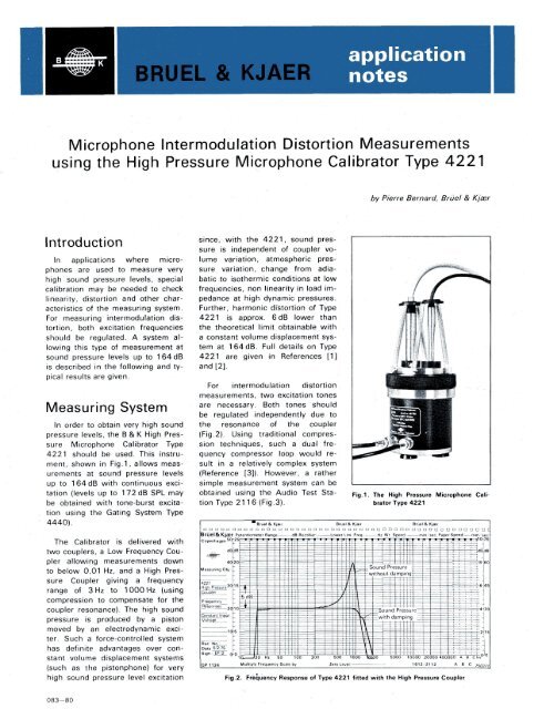
<strong>Microphone</strong> <strong>Intermodulation</strong> <strong>Distortion</strong> Measurements<br />
<strong>usin</strong>g the High Pressure <strong>Microphone</strong> Calibrator Type 4221<br />
IntTOdurtion since, with the 4221, sound pressure<br />
is independent of coupler vo-<br />
In applications where micro- lume variation, atmospheric presphones<br />
are used to measure very sure variation, change from adiahigh<br />
sound pressure levels, special batic to isothermic conditions at low<br />
calibration may be needed to check frequencies, non linearity in load imlinearity,<br />
distortion and other char- pedance at high dynamic pressures.<br />
acteristics of the measuring system. Further, harmonic distortion of Type<br />
For measuring intermodulation dis- 4221 is approx. 6dB lower than<br />
tortion, both excitation frequencies the theoretical limit obtainable with<br />
should be regulated. A system al- a constant volume displacement syslowing<br />
this type of measurement at tern at 164dB. Full details on Type<br />
sound pressure levels up to 164dB 4221 are given in References [1]<br />
is described in the following and ty- and [2].<br />
pical results are given.<br />
For intermodulation distortion,<br />
measurements, two excitation tones<br />
MPBSUrinQ SvStfim are necessar V- Botn tones should<br />
** be regulated independently due to<br />
In order to obtain very high sound the resonance of the coupler<br />
pressure levels, the B & K High Pres- (Fig.2). Using traditional compressure<br />
<strong>Microphone</strong> Calibrator Type sion techniques, such a dual fre-<br />
4221 should be used. This instru- quency compressor loop would rement,<br />
shown in Fig. 1, allows meas- suit in a relatively complex system<br />
urements at sound pressure levels (Reference [3]). However, a rather<br />
up to 164dB with continuous exci- simple measurement system can be<br />
tation (levels up to 172dB SPL may obtained <strong>usin</strong>g the Audio Test Stabe<br />
obtained with tone-burst excitatinn<br />
tion iicinn <strong>usin</strong>g thp the Gating fnPtinn 5-wsfpm System Tvne Type<br />
4440).<br />
tion Type 21 1 6 (Fig.3).<br />
The Calibrator is delivered with<br />
two couplers, a Low Frequency Coupler<br />
allowing measurements down<br />
to below 0,01 Hz, and a High Pressure<br />
Coupler giving a frequency<br />
range of 3 Hz to 1000 Hz (<strong>usin</strong>g<br />
compression to compensate for the<br />
coupler resonance). The high sound<br />
pressure is produced by a piston<br />
moved by an electrodynamic exciter.<br />
Such a force-controlled system<br />
has definite advantages over constant<br />
volume displacement systems<br />
(such as the pistonphone) for very<br />
high sound pressure level excitation<br />
083—80<br />
by Pierre Bernard, Bruel & Kjasr<br />
Fig.1. The High Pressure <strong>Microphone</strong> Calibrator<br />
Type 4221<br />
Fig.2. Frequency Response of Type 4221 fitted with the High Pressure Coupler
Fig.3. The Audio Test Station Type 2116<br />
The instrument includes a generator<br />
(100 Hz to 10 kHz), an analyzer/recorder<br />
section and a memory<br />
which can store the frequency response<br />
of a test object and automatically<br />
compensate possible irregularities<br />
during later frequency sweeps.<br />
In the <strong>Intermodulation</strong> <strong>Distortion</strong><br />
mode of Type 2116, two tones with<br />
a constant frequency ratio of 1,4<br />
are produced, each being individually<br />
regulated <strong>usin</strong>g the proper attenuation<br />
factors stored in the memory<br />
so that they both have the<br />
same amplitude over the frequency<br />
range of interest. Both second and<br />
third intermodulation distortion product<br />
can be measured by the 2116<br />
(f2 — f i and 2f i — f2 respectively,<br />
where fi and f'2' are both excitation<br />
frequencies, related by f2 - 1,4fi).<br />
Second and third harmonic distortion<br />
products can also be measured<br />
(see Fig.4).<br />
The complete measuring system<br />
is shown in Fig.5. The output of the<br />
2116 is not sufficient to drive the<br />
4221 at full rating. The excitation<br />
signal is therefore fed to the Power<br />
Amplifier Type 2706. The sound<br />
pressure level in the coupler can be<br />
read on the Measuring Amplifier<br />
Type 2610 connected to the<br />
VOLTMETER output of the 4221. At<br />
95 Hz, a 1 mV output corresponds<br />
to 20 Pa sound pressure<br />
(1 20 dB SPL). The Measuring Amplifier<br />
is also used to condition the<br />
microphone output so that it corresponds<br />
to the measuring range of<br />
the Audio Test Station.<br />
Measurements<br />
The first step is to measure the<br />
distortion characteristics of the measuring<br />
set-up. For that purpose, a<br />
special acoustical attenuator was<br />
used so that the sound pressure level<br />
acting on the 1/4" Condenser<br />
<strong>Microphone</strong> Type 41 35 was approxi-<br />
2<br />
Fig.4. Harmonic distortion (upper) and intermodulation distortion (lower) as measured by Type<br />
2116<br />
Fig.5. Set-up for measuring harmonic and intermodulation distortion of microphones at high<br />
sound pressure levels<br />
mately 30 dB below the sound pres- ence level used when reading-in<br />
sure level in the coupler. It can the correction curve.<br />
therefore be expected that any distortion<br />
measured is produced by the The COMPRESSION switch was<br />
excitation part of the system. then set to "In" and the correction<br />
curve was recorded. The sweep<br />
With the acoustical attenuator in was stopped around 1 kHz. In this<br />
place, the 2116 was set to "Fre- way, all further sweeps <strong>usin</strong>g the requency<br />
Response" with the COM- corded correction curve stop auto-<br />
PRESSION switch set to "Out". The matically at the last recorded fre-<br />
SPL selector was set to 90dB. The quency.<br />
2116 was started. The sweep was<br />
stopped at 1 00 Hz and the gain of To check that the correction curve<br />
the Power Amplifier Type 2706 was read-in correctly, the frequency<br />
was adjusted until the reading on response of the system was rethe<br />
Measuring Preamplifier Type corded as well as second and third<br />
2610 was corresponding to a harmonic distortion components<br />
sound pressure level of 164dB in (Fig.6). <strong>Intermodulation</strong> distortion<br />
the coupler. The 2610 was then was then recorded and was found<br />
switched to the "Preamp." INPUT at least 50 dB below the excitation<br />
and the gain was adjusted so that level (Fig.7). At such low levels, the<br />
the pen of the 2116 was lying on distortion products can be of the<br />
the "90dB" line, which is the refer- same order of magnitude as hum
i . -- __ . ■ ■ , r, . . - ~ — — ~ — ■ . r<br />
Fig.6. Harmonic distortion of the measuring set-up at 164dB SPL Fig.7. <strong>Intermodulation</strong> distortion of the measuring set-up at 164dB SPL<br />
(measured with 4135 and acoustical attenuator)<br />
components. To eliminate this ef<br />
fect and check the measured inter<br />
modulation products, the signal<br />
from the microphone was fed to a<br />
Narrow Band Spectrum Analyzer<br />
Type 2031. The noise and hum<br />
spectrum was first measured (aver<br />
aging 128 spectra) and stored in<br />
the memory of the Analyzer. A<br />
sweep was then started on the<br />
2116. The sweep was stopped at<br />
one frequency and 128 spectra<br />
were averaged. The "I - M" display<br />
mode of the 2031 was used, thus<br />
eliminating hum components from<br />
the display. The result, recorded on<br />
a X-Y Recorder Type 2308, is<br />
shown in Fig.8, where the two<br />
lower intermodulation component<br />
appear lower than second and third<br />
harmonic distortion components.<br />
Another intermodulation component<br />
is seen at fi + f2, but it is still<br />
more than 35 dB below excitation le<br />
vel.<br />
Fig.8. Frequency spectrum showing excitation frequencies as well as harmonic and intermodulation<br />
distortion components of the measuring set-up at 164 dB SPL<br />
Fig.9. a) Harmonic distortion and b) <strong>Intermodulation</strong> distortion at 164dB SPL for the 4135 without acoustical attenuator<br />
3
The acoustical attenuator was<br />
removed and the measurements<br />
were repeated with the 4135 now<br />
excited at 164dB. The results are<br />
shown in Fig.9 as recorded on the<br />
2116 while Fig. 10 shows the spectrum<br />
obtained at one frequency,<br />
again <strong>usin</strong>g the "I - M" mode of the<br />
2031. Harmonic distortion of the<br />
4135 for 250 Hz fundamental frequency<br />
(see Fig. 10) is approx.<br />
2,2%, which corresponds to already<br />
published data (Reference [4]). The<br />
first intermodulation distortion product<br />
has gone up by approx. 10dB<br />
compared to Fig.8, but is still more<br />
than 40dB below excitation level.<br />
The second intermodulation product<br />
does not show a significant increase.<br />
This is also the case for the<br />
product at f i + f 2.<br />
Finally, a similar spectrum was<br />
measured <strong>usin</strong>g the 1/2 inch Condenser<br />
<strong>Microphone</strong> Type 4134 at<br />
160dB SPL, which is the specified<br />
3% harmonic distortion limit for this<br />
microphone. This spectrum (Fig.11)<br />
shows that harmonic distortion is<br />
approx. 3% and so is the component<br />
at f 1 + f2 • The second intermodulation<br />
distortion component is<br />
approx. 1%, while the second one<br />
is virtually unchanged compared to<br />
that obtained for the system itself.<br />
Conclusion<br />
Based on the Audio Test Station<br />
Type 2116 and the High Pressure<br />
<strong>Microphone</strong> Calibrator Type 4221,<br />
a simple system can be set-up to<br />
measure harmonic and intermodulation<br />
distortion of microphones at<br />
high sound pressure levels. Amplitude<br />
linearity at one frequency can<br />
also be checked simply by stepping<br />
the SPL selector of the 2116 in<br />
5dB steps. Measurements made on<br />
B & K Condenser <strong>Microphone</strong>s have<br />
shown that their intermodulation<br />
distortion is small and does not exceed<br />
harmonic distortion.<br />
References<br />
[1] "Low Impedance <strong>Microphone</strong><br />
Calibrator and its Advantages"<br />
by Erling Frederiksen, B & K<br />
Technical Review No.4-1 977.<br />
Fig.10. Frequency spectrum for dual frequency excitation at 164dB SPL of the 4135 without<br />
acoustical attenuator<br />
Fig.11. Frequency spectrum for dual frequency excitation of the 4134 at 160dB SPL<br />
[2] "High Pressure Measurements Hearing Aids" by Philip S.<br />
with the High Pressure Micro- White, B & K Application Notes<br />
phone Calibrator 4221" 16—017.<br />
Pierre Bernard and Erling Frederiksen,<br />
B & K Application [4] "Condenser <strong>Microphone</strong>s and<br />
Notes 17—231. <strong>Microphone</strong> Preamplifiers —<br />
Theory and Application Hand-<br />
[3] "Swept Measurements of Differ- book", Bruel & Kjaer Publicaence<br />
Frequency, Intermodula- tion, May 1977.<br />
tion and Harmonic <strong>Distortion</strong> of