spatial sound rendering in max/msp with vimic - McGill University
spatial sound rendering in max/msp with vimic - McGill University
spatial sound rendering in max/msp with vimic - McGill University

You also want an ePaper? Increase the reach of your titles
YUMPU automatically turns print PDFs into web optimized ePapers that Google loves.
SPATIAL SOUND RENDERING IN MAX/MSP WITH VIMIC<br />
Nils Peters 1 , Tristan Matthews 1 , Jonas Braasch 2 , Stephen McAdams 1<br />
1 Schulich School of Music - Music Technology Area, <strong>McGill</strong> <strong>University</strong>, Montréal, CA<br />
2 Rensselear Polytechnic Institute - School of Architecture, Troy, US<br />
nils.peters@mcgill.ca<br />
CIRMMT - Centre for Interdiscipl<strong>in</strong>ary Research <strong>in</strong> Music Media and Technology<br />
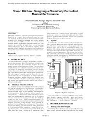
ABSTRACT<br />
Orig<strong>in</strong>ally conceptualized [2] for the software Pure Data,<br />
ViMiC was recently ref<strong>in</strong>ed and extended for release to<br />
the Max/MSP community. ViMiC (Virtual Microphone<br />
Control) is a tool for real-time <strong>spatial</strong>ization synthesis,<br />
particularly for concert situations and site-specific immersive<br />
<strong>in</strong>stallations, and especially for larger or noncentralized<br />
audiences. Based on the concept of virtual<br />
microphones positioned <strong>with</strong><strong>in</strong> a virtual 3D room, ViMiC<br />
supports loudspeaker reproduction up to 24 discrete channels<br />
for which the loudspeakers do not necessarily have to<br />
be placed uniformly and equidistant around the audience.<br />
Also, through the <strong>in</strong>tegrated Open Sound Control protocol<br />
(OSC), ViMiC is easily accessed and manipulated.<br />
1. INTRODUCTION<br />
Besides the traditional concepts of pitch, timbre, and temporal<br />
structures, composers have long felt the desire to <strong>in</strong>tegrate<br />
a <strong>spatial</strong> dimension <strong>in</strong>to their music. First, through<br />
static placement and separation of musicians <strong>in</strong> the concert<br />
space, and later, through dynamic modifications of<br />
the <strong>sound</strong> source position, effects of <strong>spatial</strong> <strong>sound</strong> segregation<br />
and fusion were discovered. In the 20th century,<br />
especially due to the <strong>in</strong>vention and <strong>in</strong>tegration of microphones<br />
and loudspeakers <strong>in</strong> the musical performance, <strong>spatial</strong>ization<br />
was popularized.<br />
One of the earliest composers us<strong>in</strong>g the newly available<br />
electronic tools was Karlhe<strong>in</strong>z Stockhausen. For his composition<br />
”Kontakte” (1958-60) he developed a rotational<br />
table, mount<strong>in</strong>g a directed loudspeaker surrounded by<br />
four stationary microphones that receive the loudspeaker<br />
signal. The recorded microphone signals were routed<br />
to different loudspeakers arranged around the audience.<br />
Due to the directivity and separation of the microphones,<br />
the recorded audio signals conta<strong>in</strong>ed Inter-channel Time<br />
Differences (ICTDs) and Inter-channel Level Differences<br />
(ICLDs). Depend<strong>in</strong>g on the velocity of the speaker rotation,<br />
the change <strong>in</strong> ICTDs can create an audible Doppler<br />
effect. ViMiC follows somehow this Stockhausen’s traditions<br />
by us<strong>in</strong>g the concept of <strong>spatial</strong>ly displaced microphones<br />
for the purpose of <strong>sound</strong> <strong>spatial</strong>ization. Relation to<br />
pioneer<strong>in</strong>g works by Ste<strong>in</strong>berg and Snow [13], Chown<strong>in</strong>g<br />
[3], and Moore [8] also apply.<br />
2. SPATIALIZATION WITH MAX/MSP<br />
This section briefly overviews available loudspeaker <strong>spatial</strong>ization<br />
techniques for Max/MSP. For further details,<br />
refer to the <strong>in</strong>dicated references.<br />
Vector Based Amplitude Pann<strong>in</strong>g (VBAP) is an efficient<br />
extension of stereophonic amplitude pann<strong>in</strong>g techniques,<br />
applied to multi-loudspeaker setups. In a horizontal plane<br />
around the listener, a virtual <strong>sound</strong> source at a certa<strong>in</strong> position<br />
is created by apply<strong>in</strong>g the tangent pann<strong>in</strong>g law between<br />
the closest pair of loudspeaker. This pr<strong>in</strong>ciple was<br />
also extended to project <strong>sound</strong> sources onto a three dimensional<br />
sphere and assumes that the listener is located <strong>in</strong> the<br />
center of the equidistant speaker setup [11].<br />
Distance Based Amplitude Pann<strong>in</strong>g (DBAP) also uses<br />
<strong>in</strong>tensity pann<strong>in</strong>g applied to arbitrary loudspeaker configurations<br />
<strong>with</strong>out assumptions as to the position of the listener.<br />
All loudspeakers radiate coherent signals, whereby<br />
the underlay<strong>in</strong>g amplitude weight<strong>in</strong>g is based on a distance<br />
attenuation model between the position of the virtual<br />
<strong>sound</strong> source and each loudspeaker [5].<br />
Higher Order Ambisonics extends Blumle<strong>in</strong>’s pioneer<strong>in</strong>g<br />
idea of co<strong>in</strong>cident record<strong>in</strong>g techniques. HOA aims to<br />
physically synthesize a <strong>sound</strong>field based on its expansion<br />
<strong>in</strong>to spherical harmonics up to a specified order. To date,<br />
Max/MSP externals up to the 3rd order for horizontal-only<br />
or periphonic speaker arrays have been presented <strong>in</strong> [12]<br />
and [14].<br />
Space Unit Generator, also called room-<strong>with</strong><strong>in</strong>-the-room<br />
model, dates back to [8]. Four loudspeakers represented<br />
as ”open w<strong>in</strong>dows” are positioned around the listener<br />
and creates an ”<strong>in</strong>ner room”, and embedded <strong>in</strong> an ”outer<br />
room” <strong>with</strong> virtual <strong>sound</strong> sources. Sound propagation of<br />
the virtual source rendered at the ”open w<strong>in</strong>dows” creates<br />
ICTDs and ICLDs. Some early reflections are calculated<br />
accord<strong>in</strong>g to the size of the outer room. A Max/MSP implementation<br />
was presented <strong>in</strong> [17].<br />
Spatialisateur, <strong>in</strong> development at IRCAM and Espaces<br />
Nouveaux s<strong>in</strong>ce 1991, is a library of <strong>spatial</strong>ization algorithms,<br />
<strong>in</strong>clud<strong>in</strong>g VBAP, first-order Ambisonics and<br />
stereo techniques (XY, MS, ORTF) for up to 8 loudspeakers.<br />
It can also reproduce 3D <strong>sound</strong> for headphones (b<strong>in</strong>aural)<br />
or 2/4 loudspeakers (transaural). A room model is<br />
<strong>in</strong>cluded to create artificial reverberation controlled by a<br />
perceptual-based user <strong>in</strong>terface.
3. VIRTUAL MICROPHONE CONTROL<br />
ViMiC is a key part of the network music project Sound-<br />
WIRE 1 , and the T<strong>in</strong>t<strong>in</strong>nabulate Ensemble 2 directed by<br />
Paul<strong>in</strong>e Oliveros. At the MusiMars Festival 2008 3 , Ex<br />
Asperis, a composition by Sean Ferguson, featured ViMiC<br />
for Max/MSP and <strong>in</strong>tegrated gestural controllers to manipulate<br />
ViMiC <strong>sound</strong> <strong>render<strong>in</strong>g</strong> processes <strong>in</strong> various<br />
ways.<br />
ViMiC is a computer-generated virtual environment,<br />
where ga<strong>in</strong>s and delays between a virtual <strong>sound</strong> source<br />
and virtual microphones are calculated accord<strong>in</strong>g to their<br />
distances, and the axis orientations of their microphone<br />
directivity patterns. Besides the direct <strong>sound</strong> component,<br />
a virtual microphone signal can also <strong>in</strong>clude early reflections<br />
and a late reverb tail, both dependent upon the <strong>sound</strong><br />
absorb<strong>in</strong>g and reflect<strong>in</strong>g properties of the virtual surfaces.<br />
3.1. ViMiC Pr<strong>in</strong>ciples<br />
ViMiC is based on an array of virtual microphones <strong>with</strong><br />
simulated directivity patterns placed <strong>in</strong> a virtual room.<br />
3.1.1. Source - Microphone Relation<br />
Sound sources and microphones can be placed and moved<br />
<strong>in</strong> 3D as desired. Figure 3 shows an example of one <strong>sound</strong><br />
source recorded <strong>with</strong> three virtual microphones. A virtual<br />
microphone has five degrees of freedom: (X, Y, Z,<br />
yaw, pitch) and a <strong>sound</strong> source has four: (X, Y, Z, yaw).<br />
The propagation path between a <strong>sound</strong> source and each<br />
microphone is accord<strong>in</strong>gly simulated. Depend<strong>in</strong>g on the<br />
speed-of-<strong>sound</strong> c and the distance di between a virtual<br />
<strong>sound</strong> source and the i-th microphone, time-of-arrival and<br />
attenuation due to distance are estimated. This attenuation<br />
function, seen <strong>in</strong> Eq. 1 can be greatly modified by chang<strong>in</strong>g<br />
the exponent q. Thus, the effect of distance attenuation<br />
can be boosted or softened. The m<strong>in</strong>imum distance to<br />
a microphone is limited to 1 meter <strong>in</strong> order to avoid high<br />
amplification.<br />
gi = 1<br />
d q<br />
i<br />
d ≥ 1 (1)<br />
Further attenuation happens through the chosen microphone<br />
characteristic and source directivity (see Fig. 2).<br />
For all common microphone characteristics, the directivity<br />
for a certa<strong>in</strong> angle of <strong>in</strong>cidence δ can be imitated by<br />
calculat<strong>in</strong>g Eq. 2 and apply<strong>in</strong>g a set of microphone coefficients<br />
from Table 3.1.1. By <strong>in</strong>creas<strong>in</strong>g the exponent w to<br />
a value greater than 1 will produce an artificially sharper<br />
directivity pattern. Unlike actual microphone characteristics,<br />
which vary <strong>with</strong> frequency, microphones <strong>in</strong> ViMiC<br />
are designed to apply the concept of microphone directivity<br />
<strong>with</strong>out simulat<strong>in</strong>g undesirable frequency dependencies.<br />
Γ = (a + b · cos δ) w<br />
0 ≤ a, b ≤ 1 (2)<br />
1 http://ccrma.stanford.edu/groups/<strong>sound</strong>wire/<br />
2 http://www.myspace.com/t<strong>in</strong>t<strong>in</strong>nabulate<br />
3 http://www.music.mcgill.ca/musimars/<br />
Characteristic a b w<br />
Omnidirectional 1 0 1<br />
Subcardioid 0.7 0.3 1<br />
Cardioid 0.5 0.5 1<br />
Supercardioid 0.33 0.67 1<br />
Hypercardioid 0.3 0.7 1<br />
Figure-of-8 0 1 1<br />
Figure 1. Common microphone characteristics<br />
Source directivity is known to contribute to immersion<br />
and presence. Therefore ViMiC is also equipped <strong>with</strong> a<br />
source directivity model. For the sake of simplicity, <strong>in</strong><br />
a graphical control w<strong>in</strong>dow, the source directivity can be<br />
modeled through a frequency <strong>in</strong>dependent ga<strong>in</strong> factor for<br />
each radiation angle to a 1 ◦ accuracy.<br />
3.1.2. Room model<br />
ViMiC conta<strong>in</strong>s a shoe-box room model to generate timeaccurate<br />
early reflections that <strong>in</strong>crease the illusion of this<br />
virtual space and envelopment as described <strong>in</strong> the literature<br />
[9]. Early reflections are strong auditory cues <strong>in</strong> encod<strong>in</strong>g<br />
the <strong>sound</strong> source distance. Accord<strong>in</strong>g to virtual<br />
room size and position of the microphones, adequate early<br />
reflections are rendered <strong>in</strong> 3D through the well-known image<br />
method [1]. Each image source is rendered accord<strong>in</strong>g<br />
to the time of arrival, the distance attenuation, microphone<br />
characteristic and source directivity, as described<br />
<strong>in</strong> section 3.1.1. Virtual room dimensions (height, length,<br />
width) modified <strong>in</strong> real-time alter the refection pattern accord<strong>in</strong>gly.<br />
The spectral <strong>in</strong>fluence of the wall properties<br />
are simulated through high-mid-low shelf-filters. Because<br />
larger propagation paths <strong>in</strong>crease the audible effect of air<br />
absorption, early reflections <strong>in</strong> ViMiC are additionally filtered<br />
through a 2nd-order Butterworth lowpass filter <strong>with</strong><br />
adjustable cut-off frequency.<br />
Also, early reflections must be discretely rendered for<br />
each microphone, as propagation paths differ. For eight<br />
virtual microphones, 56 paths are rendered if the 1st-order<br />
reflections are considered (8 microphones · [6 early reflections<br />
+ 1 direct <strong>sound</strong> path]). Although time delays are<br />
efficiently implemented through a shared multi-tap delay<br />
l<strong>in</strong>e, this process<strong>in</strong>g can be computationally <strong>in</strong>tensive.<br />
3.2. Late Reverb<br />
The late reverberant field of a room is often considered<br />
nearly diffuse <strong>with</strong>out directional <strong>in</strong>formation. Thus, an<br />
efficient late reverb model, based on a feedback delay<br />
network [4] <strong>with</strong> 16 modulated delay l<strong>in</strong>es diffused by a<br />
Hadamard mix<strong>in</strong>g matrix, is used. By feed<strong>in</strong>g the outputs<br />
of the room model <strong>in</strong>to the late reverb a diffused reverb
tail is synthesized (see Fig. 2), for which timbral and temporal<br />
character can be modified. This late reverb can be<br />
efficiently shared across several rendered <strong>sound</strong> sources.<br />
Source Parameter<br />
Orientation<br />
[φ ]<br />
s<br />
Directivity<br />
[Γ s]<br />
Monaural<br />
Audio<br />
Input<br />
Position<br />
[x s,y<br />
s,z<br />
s]<br />
Multitap<br />
Delay<br />
...<br />
Room Model Parameter<br />
Room size<br />
[x,y,z] Number of<br />
Reflections [M]<br />
Image Source<br />
Model<br />
...<br />
Determ<strong>in</strong><strong>in</strong>g<br />
(M+1)*N<br />
Delay and Ga<strong>in</strong><br />
values<br />
...<br />
...<br />
Render<strong>in</strong>g<br />
N virtual<br />
Microphone<br />
Signals<br />
...<br />
FDN Late Reverb<br />
N channel<br />
Wall reflection<br />
coefficients<br />
Microphone Parameter<br />
Air Absorption<br />
coefficients<br />
Orientation<br />
[φ ]<br />
i<br />
Prega<strong>in</strong><br />
Quantity<br />
[N]<br />
Position<br />
[x ,y ,z ]<br />
i i i<br />
[G ] i<br />
Directivity<br />
[Γ i]<br />
Figure 2. Flowchart of the Max/MSP process<strong>in</strong>g<br />
...<br />
4. MOVING SOURCES<br />
...<br />
N<br />
Channel<br />
Output<br />
In Figure 4 the <strong>sound</strong> source moved from (x, y, z) to<br />
(x ′ , y ′ , z ′ ), chang<strong>in</strong>g the propagation paths to all microphones,<br />
and also, the time delay and attenuation. A cont<strong>in</strong>uous<br />
change <strong>in</strong> time delay engenders a pitch change<br />
(Doppler effect) that creates a very realistic impression of<br />
a mov<strong>in</strong>g <strong>sound</strong> source. Doppler effect might not always<br />
be desired. ViMiC accommodates both scenarios.<br />
4.1. Render<strong>in</strong>g <strong>with</strong> Doppler effect<br />
For each changed <strong>sound</strong> path, the change <strong>in</strong> time delay<br />
is addressed through a 4-pole <strong>in</strong>terpolated delay-l<strong>in</strong>e, the<br />
perceived quality of which is significantly better than <strong>with</strong><br />
an economical l<strong>in</strong>ear <strong>in</strong>terpolation. To save resources, <strong>in</strong>terpolation<br />
is only applied when mov<strong>in</strong>g the virtual <strong>sound</strong><br />
source, otherwise the time delay is be<strong>in</strong>g rounded to the<br />
next non-fractional delay value. At fs = 44.1 kHz and a<br />
speed-of-<strong>sound</strong> of c = 344 m/s, the roundoff error is approximately<br />
4 mm. Some discrete reflections might not be<br />
perceptually important due to the applied distance law, microphone<br />
characteristics, and source directivity. To m<strong>in</strong>imize<br />
processor load, an amplitude threshold can be set to<br />
prevent the algorithm from <strong>render<strong>in</strong>g</strong> these reflections.<br />
4.2. Render<strong>in</strong>g <strong>with</strong>out Doppler effect<br />
This render method works <strong>with</strong>out <strong>in</strong>terpolation: the time<br />
delays of the rendered <strong>sound</strong> paths rema<strong>in</strong>s static until one<br />
of the paths has been changed by more than a specified<br />
time delay. In this case, the <strong>sound</strong> paths of the old and the<br />
new <strong>sound</strong> position are cross-faded <strong>with</strong><strong>in</strong> 50 ms, <strong>in</strong> order<br />
to avoid strongly audible phase modulations.<br />
φ 1<br />
δ 1<br />
Mic 1<br />
(x1,y1,z1)<br />
φ<br />
1<br />
δ'1 Mic 1<br />
(x1,y1,z1)<br />
Orientation<br />
y<br />
z<br />
x<br />
(0, 0, 0)<br />
d 1<br />
Sound Source<br />
(x ′ S,y ′ S,z ′ S)<br />
d' 1<br />
y<br />
z<br />
φ 2<br />
Mic 2<br />
(x2,y2,z2)<br />
δ 2<br />
Orientation<br />
Sound Source<br />
(xS,yS,zS) φS d 2<br />
δ 3<br />
φ 3<br />
Mic 3<br />
(x3,y3,z3)<br />
Figure 3. Geometric pr<strong>in</strong>ciples<br />
x<br />
(0, 0, 0)<br />
φ S<br />
d' 2<br />
Orientation<br />
φ 2<br />
δ' 2<br />
Mic 2<br />
(x2,y2,z2)<br />
d' 3<br />
δ' 3<br />
d 3<br />
Orientation<br />
(xS,yS,zS)<br />
φ 3<br />
Mic 3<br />
(x3,y3,z3)<br />
Orientation<br />
Orientation<br />
Figure 4. Mov<strong>in</strong>g source, geometric pr<strong>in</strong>ciples<br />
5. PRACTICAL CONSIDERATIONS<br />
5.1. How to set up the virtual microphones?<br />
Typically, each virtual microphone is associated <strong>with</strong> one<br />
loudspeaker, and should be oriented at the same angle as<br />
the loudspeaker. The more spaced the microphones are,<br />
the bigger the ICTDs will be. The use of virtual microphones<br />
is especially <strong>in</strong>terest<strong>in</strong>g for arrays of speakers <strong>with</strong><br />
different elevation angles, because the time-delay based<br />
pann<strong>in</strong>g possibilities help to project elevated <strong>sound</strong>s. Although<br />
ViMiC is a 24-channel system, for smaller loudspeaker<br />
setups the number of virtual microphones can be<br />
reduced. For surround record<strong>in</strong>gs for the popular ITU
5.1 speaker configuration, Tonmeisters developed different<br />
microphone setups (e.g. [15]) applicable <strong>in</strong> ViMiC. To<br />
ease plac<strong>in</strong>g and modify<strong>in</strong>g of the microphone positions,<br />
ViMiC provides an extra user <strong>in</strong>terface where an array of<br />
microphones can either be graphically 4 edited or def<strong>in</strong>ed<br />
through cartesian and spherical coord<strong>in</strong>ates (Fig. 5).<br />
Figure 5. Interface to position microphones<br />
5.2. Controllability<br />
For easier and more flexible controllability, ViMiC was<br />
structured as high-level modules us<strong>in</strong>g the Jamoma framework<br />
for Max/MSP [10]. Jamoma offers a clear advantage<br />
<strong>in</strong> its standardization of presets and parameter handl<strong>in</strong>g.<br />
The ViMiC parameters have been sorted <strong>in</strong>to three<br />
primary namespaces: source, microphone and room; and<br />
are specified <strong>with</strong> a data range. ViMiC is fully controlled<br />
through a GUI and through external OSC-messages [16]:<br />
/source/orientation/azimuth/degree 45<br />
/microphones/3/directivity/ratio 0.5<br />
/room/size/xyz 10. 30. 7.<br />
OSC enables the access and manipulation of ViMiC via<br />
different hardware controllers, track<strong>in</strong>g devices or user <strong>in</strong>terfaces<br />
through OSC mapp<strong>in</strong>g applications (e.g. [6]) and<br />
allows gestural control of <strong>spatial</strong>ization <strong>in</strong> real-time [7].<br />
6. FUTURE WORK<br />
Currently, a ViMiC module renders one <strong>sound</strong> source.<br />
Plans to develop an object which handles multiple <strong>sound</strong><br />
source and frequency dependent source directivity are under<br />
discussion. ViMiC for Max/MSP under MacOS is<br />
available <strong>in</strong> the Subversion repository of Jamoma 5 .<br />
7. ACKNOWLEDGMENT<br />
This work has been funded by the Canadian Natural Sciences<br />
and Eng<strong>in</strong>eer<strong>in</strong>g Research Council (NSERC) and<br />
the Centre for Interdiscipl<strong>in</strong>ary Research <strong>in</strong> Music, Media<br />
and Technology (CIRMMT).<br />
4 The [Ambimonitor] by ICST is used to display microphones[12].<br />
5 https://jamoma.svn.sourceforge.net/svnroot/<br />
jamoma/branches/active<br />
References<br />
[1] J. B. Allen and D. A. Berkley. Image method for efficiently<br />
simulat<strong>in</strong>g small-room acoustics. J. Acoust. Soc.<br />
Am., 65(4):943 – 950, 1979.<br />
[2] J. Braasch. A loudspeaker-based 3D <strong>sound</strong> projection us<strong>in</strong>g<br />
Virtual Microphone Control (ViMiC). In Convention of<br />
the AudioEng. Soc. 118, Prepr<strong>in</strong>t 6430, Barcelona, Spa<strong>in</strong>,<br />
2005.<br />
[3] J. M. Chown<strong>in</strong>g. The simulation of mov<strong>in</strong>g <strong>sound</strong> sources.<br />
JAES, 19(1):2 – 6, 1971.<br />
[4] J. Jot and A. Chaigne. Digital delay networks for design<strong>in</strong>g<br />
artificial reverberators. In 90th AES Convention, Prepr<strong>in</strong>t<br />
3030, Paris, France, 1991.<br />
[5] T. Lossius. Sound Space Body: Reflections on Artistic<br />
Practice. PhD thesis, Bergen National Academy of the<br />
Arts, 2007.<br />
[6] J. Malloch, S. S<strong>in</strong>clair, and M. M. Wanderley. From controller<br />
to <strong>sound</strong>: Tools for collaborative development of<br />
digital musical <strong>in</strong>struments. In Proceed<strong>in</strong>gs of the International<br />
Computer Music Conference, pages 65–72, Copenhagen,<br />
Denmark, 2007.<br />
[7] M. Marshall, N. Peters, A. Jensenius, J. Boiss<strong>in</strong>ot, M. Wanderley,<br />
and J. Braasch. On the development of a system<br />
for gesture control of <strong>spatial</strong>ization. In Proceed<strong>in</strong>gs of<br />
the 2006 International Computer Music Conference, pages<br />
360–366, 2006.<br />
[8] F. R. Moore. A General Model for Spatial Process<strong>in</strong>g of<br />
Sounds. Computer Music Journal, 7(6):6 – 15, 1983.<br />
[9] R. Pellegr<strong>in</strong>i. Perception-based design of virtual rooms for<br />
<strong>sound</strong> reproduction. In 22nd AES International Conference,<br />
Prepr<strong>in</strong>t 000245, 2002.<br />
[10] T. Place and T. Lossius. Jamoma: A modular standard for<br />
structur<strong>in</strong>g patches <strong>in</strong> Max. In Proceed<strong>in</strong>gs of the International<br />
Computer Music Conference 2006, New Orleans,<br />
US, 2006.<br />
[11] V. Pulkki. Generic pann<strong>in</strong>g tools for MAX/MSP. Proceed<strong>in</strong>gs<br />
of International Computer Music Conference, pages<br />
304–307, 2000.<br />
[12] J. C. Schacher and P. Kocher. Ambisonics Spatialization<br />
Tools for Max/MSP. In Proceed<strong>in</strong>gs of the 2006 International<br />
Computer Music Conference, pages 274 – 277, New<br />
Orleans, US, 2006.<br />
[13] J. Ste<strong>in</strong>berg and W. Snow. Auditory Perspective-Physical<br />
Factors. Electrical Eng<strong>in</strong>eer<strong>in</strong>g, 53(1):12–15, 1934.<br />
[14] G. Wakefield. Third-Order Ambisonic Extension for<br />
Max/MSP <strong>with</strong> Musical Applications. In Proceed<strong>in</strong>gs of<br />
the 2006 International Computer Music Conference, pages<br />
123 – 126, New Orleans, US, 2006.<br />
[15] M. Williams and G. Le Dû. The Quick Reference Guide<br />
to Multichannel Microphone Arrays, Part 2: us<strong>in</strong>g Supercardioid<br />
and Hypercardioid Microphones. In 116th AES<br />
Convention, Prepr<strong>in</strong>t 6059, Berl<strong>in</strong>, Germany, May 8–11<br />
2004.<br />
[16] M. Wright and A. Freed. Open Sound Control: A New Protocol<br />
for Communicat<strong>in</strong>g <strong>with</strong> Sound Synthesizers. Proceed<strong>in</strong>gs<br />
of the 1997 International Computer Music Conference,<br />
pages 101–104, 1997.<br />
[17] S. Yadegari, F. R. Moore, H. Castle, A. Burr, and T. Apel.<br />
Real-time implementation of a general model for <strong>spatial</strong><br />
process<strong>in</strong>g of <strong>sound</strong>s. In Proceed<strong>in</strong>gs of the 2002 International<br />
Computer Music Conference, pages 244 – 247, San<br />
Francisco, CA, USA, 2002.