Manual LCP-104 PC-Control Panel Mikrap AG
Manual LCP-104 PC-Control Panel Mikrap AG
Manual LCP-104 PC-Control Panel Mikrap AG
- TAGS
- manual
- panel
- mikrap
- www.mikrap.ch

Create successful ePaper yourself
Turn your PDF publications into a flip-book with our unique Google optimized e-Paper software.
<strong>Mikrap</strong> <strong>PC</strong>-<strong>Control</strong> <strong>Panel</strong> <strong>LCP</strong>-<strong>104</strong><br />
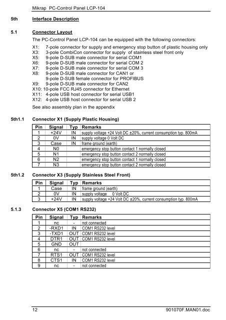
5th Interface Description<br />
5.1 Connector Layout<br />
The <strong>PC</strong>-<strong>Control</strong> <strong>Panel</strong> <strong>LCP</strong>-<strong>104</strong> can be equipped with the following connectors:<br />
X1: 7-pole connector for supply and emergency stop button of plastic housing only<br />
X3: 3-pole CombiCon connector for supply of stainless steel front only<br />
X5: 9-pole D-SUB male connector for serial COM1<br />
X6: 9-pole D-SUB male connector for serial COM 2<br />
X7: 9-pole D-SUB male connector for serial COM 3<br />
X8: 9-pole D-SUB male connector for CAN1 or<br />
9-pole D-SUB female connector for PROFIBUS<br />
X9: 9-pole D-SUB male connector for CAN2<br />
X10: 10-pole FCC RJ45 connector for Ethernet<br />
X11: 4-pole USB host connector for serial USB1<br />
X12: 4-pole USB host connector for serial USB 2<br />
See also assembly plan in the appendix<br />
5th1.1 Connector X1 (Supply Plastic Housing)<br />
Pin Signal Typ Remarks<br />
1 +24V IN supply voltage +24 Volt DC ±20%, current consumption typ. 800mA<br />
2 0V IN supply voltage 0 Volt DC<br />
3 Case IN frame ground (earth)<br />
4 N0 emergency stop button contact 1 normally closed<br />
5 N1 emergency stop button contact 2 normally closed<br />
6 N2 emergency stop button contact 1 normally closed<br />
7 N3 emergency stop button contact 2 normally closed<br />
5th1.2 Connector X3 (Supply Stainless Steel Front)<br />
Pin Signal Typ Remarks<br />
1 Case IN frame ground (earth)<br />
2 0V IN supply voltage 0 Volt DC<br />
3 +24V IN supply voltage +24 Volt DC ±20%, current consumption typ. 800mA<br />
5.1.3 Connector X5 (COM1 RS232)<br />
Pin Signal Typ Remarks<br />
1 nc - not connected<br />
2 -RXD1 IN COM1 RS232 level<br />
3 -TXD1 OUT COM1 RS232 level<br />
4 DTR1 OUT COM1 RS232 level<br />
5 GND OUT<br />
6 nc - not connected<br />
7 RTS1 OUT COM1 RS232 level<br />
8 CTS1 IN COM1 RS232 level<br />
9 nc - not connected<br />
12 901070F.MAN01.doc