MK-3000 Series, MK2-3000 Series, MK4-3000 Series
MK-3000 Series, MK2-3000 Series, MK4-3000 Series
MK-3000 Series, MK2-3000 Series, MK4-3000 Series
- TAGS
- series
- www.tac.com

You also want an ePaper? Increase the reach of your titles
YUMPU automatically turns print PDFs into web optimized ePapers that Google loves.
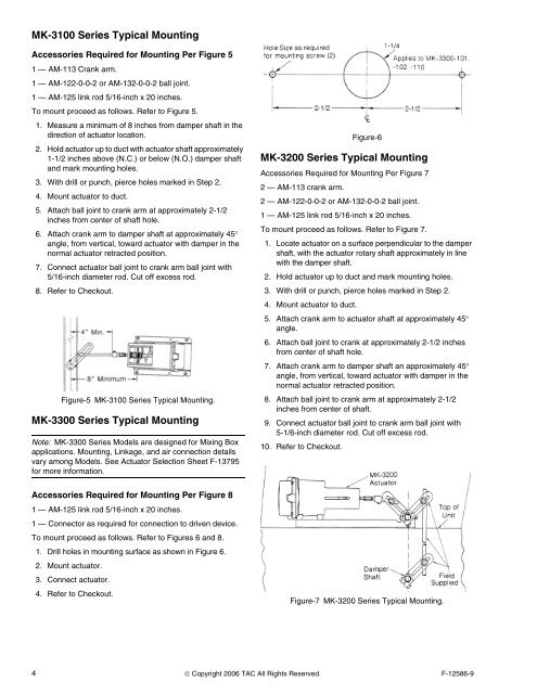
<strong>MK</strong>-3100 <strong>Series</strong> Typical Mounting<br />
Accessories Required for Mounting Per Figure 5<br />
1 — AM-113 Crank arm.<br />
1 — AM-122-0-0-2 or AM-132-0-0-2 ball joint.<br />
1 — AM-125 link rod 5/16-inch x 20 inches.<br />
To mount proceed as follows. Refer to Figure 5.<br />
1. Measure a minimum of 8 inches from damper shaft in the<br />
direction of actuator location.<br />
2. Hold actuator up to duct with actuator shaft approximately<br />
1-1/2 inches above (N.C.) or below (N.O.) damper shaft<br />
and mark mounting holes.<br />
3. With drill or punch, pierce holes marked in Step 2.<br />
4. Mount actuator to duct.<br />
5. Attach ball joint to crank arm at approximately 2-1/2<br />
inches from center of shaft hole.<br />
6. Attach crank arm to damper shaft at approximately 45°<br />
angle, from vertical, toward actuator with damper in the<br />
normal actuator retracted position.<br />
7. Connect actuator ball joint to crank arm ball joint with<br />
5/16-inch diameter rod. Cut off excess rod.<br />
8. Refer to Checkout.<br />
Figure-5 <strong>MK</strong>-3100 <strong>Series</strong> Typical Mounting.<br />
<strong>MK</strong>-3300 <strong>Series</strong> Typical Mounting<br />
Note: <strong>MK</strong>-3300 <strong>Series</strong> Models are designed for Mixing Box<br />
applications. Mounting, Linkage, and air connection details<br />
vary among Models. See Actuator Selection Sheet F-13795<br />
for more information.<br />
Accessories Required for Mounting Per Figure 8<br />
1 — AM-125 link rod 5/16-inch x 20 inches.<br />
1 — Connector as required for connection to driven device.<br />
To mount proceed as follows. Refer to Figures 6 and 8.<br />
1. Drill holes in mounting surface as shown in Figure 6.<br />
2. Mount actuator.<br />
3. Connect actuator.<br />
4. Refer to Checkout.<br />
Figure-6<br />
<strong>MK</strong>-3200 <strong>Series</strong> Typical Mounting<br />
Accessories Required for Mounting Per Figure 7<br />
2 — AM-113 crank arm.<br />
2 — AM-122-0-0-2 or AM-132-0-0-2 ball joint.<br />
1 — AM-125 link rod 5/16-inch x 20 inches.<br />
To mount proceed as follows. Refer to Figure 7.<br />
1. Locate actuator on a surface perpendicular to the damper<br />
shaft, with the actuator rotary shaft approximately in line<br />
with the damper shaft.<br />
2. Hold actuator up to duct and mark mounting holes.<br />
3. With drill or punch, pierce holes marked in Step 2.<br />
4. Mount actuator to duct.<br />
5. Attach crank arm to actuator shaft at approximately 45°<br />
angle.<br />
6. Attach ball joint to crank at approximately 2-1/2 inches<br />
from center of shaft hole.<br />
7. Attach crank arm to damper shaft an approximately 45°<br />
angle, from vertical, toward actuator with damper in the<br />
normal actuator retracted position.<br />
8. Attach ball joint to crank arm at approximately 2-1/2<br />
inches from center of shaft.<br />
9. Connect actuator ball joint to crank arm ball joint with<br />
5-1/6-inch diameter rod. Cut off excess rod.<br />
10. Refer to Checkout.<br />
Figure-7 <strong>MK</strong>-3200 <strong>Series</strong> Typical Mounting.<br />
4 © Copyright 2006 TAC All Rights Reserved. F-12586-9