MK-3000 Series, MK2-3000 Series, MK4-3000 Series
MK-3000 Series, MK2-3000 Series, MK4-3000 Series
MK-3000 Series, MK2-3000 Series, MK4-3000 Series
- TAGS
- series
- www.tac.com

You also want an ePaper? Increase the reach of your titles
YUMPU automatically turns print PDFs into web optimized ePapers that Google loves.
CHECKOUT<br />
After installation, the actuator should be checked to insure<br />
proper damper operation. To check the actuator and linkage,<br />
proceed as follows:<br />
1. Check the linkage with the actuator in the retracted<br />
position for proper return force. The actuator should be<br />
linked so that on a normally closed application, the damper<br />
is closed with no more than 1/16-inch compression of the<br />
spring. (The actuator shaft would return an additional<br />
1/16-inch if the linkage were disconnected.) For a normally<br />
open application, the actuator should be linked with the<br />
actuator fully retracted.<br />
2. Apply air pressure to the actuator or pilot port of a<br />
positioner and check the linkage as follows. On a<br />
normally closed application, the damper should be just<br />
full open when the actuator piston reaches the stops in<br />
the actuator. On a normally open application, the damper<br />
should reach the closed position with no more than<br />
1/16-inch stroke remaining to reach the actuator stops.<br />
3. The above can be obtained through adjustment of the ball<br />
joint in the crank arms or by adjustment of the actuator<br />
stops. The amount of thread engagement of the actuator<br />
ball joint or extension shaft may also be used to assist in<br />
proper linking.<br />
Connection of Air Line: On pivot mounting arrangements,<br />
Figures 9, 10 and 12, control air lines MUST be terminated at<br />
the actuator with at least 6 inches of flexible tubing to allow for<br />
pivoting of the actuator. On mounting arrangements, Figures<br />
5, 7 and 8, control air lines may be connected directly with<br />
either copper or plastic tubing, as required by application.<br />
Caution: On <strong>MK</strong>2-31X1 <strong>Series</strong>, metal connectors and tubing<br />
must be used.<br />
Adjustable Starting Pressure: Actuators are available with<br />
adjustable starting pressure. To adjust the starting pressure,<br />
turn adjusting nut supporting the spring clockwise to increase<br />
and counterclockwise to decrease the starting pressure. Each<br />
rotation of the adjusting nut changes the starting pressure .04<br />
psi (.28 kPa).<br />
Adjustable Stroke Length: Stroke length is determined by<br />
the two stops located on either side of the actuator. Stops are<br />
set for 3-1/2-inch stroke. mark this point and measure toward<br />
the diaphragm end of the actuator to reduce the stroke or<br />
away from the diaphragm end to increase the stroke.<br />
Maximum stroke length is 4 inches. By increasing the stroke<br />
length, the force available to resist an opposing force is<br />
decreased while decreasing the stroke length increases this<br />
force.<br />
Diaphragm Replacement: If the actuator diaphragm should<br />
leak, it may easily be replaced by removing the four screws<br />
holding the top power housing. Make sure that shaft swivel<br />
joint is in place on the end of the shaft. Remove the screws<br />
and old diaphragm. Roll the new diaphragm inside out and<br />
install over the piston making sure the circular bead is facing<br />
up. Put the top power housing back in place making sure the<br />
bead on the diaphragm is in the housing groove and the screw<br />
holes are lined up. Tighten housing screws.<br />
UNITS WITH FACTORY MOUNTED<br />
POSITIVE POSITIONERS<br />
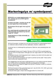
Figure-16 Typical Factory Mounted Positioner.<br />
For Actuators with Positioners:<br />
Note: If actuator is frame pivot mounted, the actuator must<br />
be mounted to the left-hand frame. If actuator is mounted<br />
external, Figure 12 must be on right-hand side of duct.<br />
Install fittings required in Ports 2 and 3.<br />
ADJUSTMENTS<br />
Refer to Figure 16.<br />
Range Adjustment: Adjustable 2 to 10 psig (14 to 69 kPa).<br />
Factory set at 5 psig (34 kPa). Range is the pressure change<br />
required to produce full actuator stroke.<br />
If adjustment is required (see Figure 16), with a small<br />
screwdriver loosen screw on range slider approximately 1/2<br />
turn.<br />
Move the graduated range slider until desired pressure mark<br />
lines up with center of screw and tighten screw.<br />
Start Point: Adjustable 2 to 10 psig (14 to 69 kPa). Start point<br />
is the pressure at which the actuator just begins to extend.<br />
See Figure 16.<br />
Connect main air supply to Port 3 and a variable air supply to<br />
Port 2.<br />
1. Adjust variable air supply on Port 2 to desired start point<br />
pressure.<br />
2. Adjust the start point screw with small screwdriver until<br />
actuator just starts to extend.<br />
3. Gradually raise pressure on Port 2 until actuator is fully<br />
extended, and readjust range slider to obtain desired<br />
range if further adjustment is necessary.<br />
4. Remove variable air supply from Port 2 and connect to<br />
controller output.<br />
F-12586-9 © Copyright 2006 TAC All Rights Reserved. 7