Colloidal Processing of Ceramics
Colloidal Processing of Ceramics
Colloidal Processing of Ceramics

You also want an ePaper? Increase the reach of your titles
YUMPU automatically turns print PDFs into web optimized ePapers that Google loves.
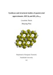
CHAPTER 9<br />
<strong>Colloidal</strong> <strong>Processing</strong> <strong>of</strong> <strong>Ceramics</strong><br />
Lennart Bergström<br />
Institute for Surface Chemistry, Stockholm, Sweden<br />
1 Introduction ....................... 201<br />
2 Powder <strong>Processing</strong> <strong>of</strong> <strong>Ceramics</strong> ........ 202<br />
2.1 <strong>Colloidal</strong> processing ............. 203<br />
3 Interparticle Forces and <strong>Colloidal</strong><br />
Stability .......................... 203<br />
3.1 van der Waals forces ............ 203<br />
3.2 Electrostatic double-layer<br />
forces ....................... 204<br />
3.3 Polymer-induced forces .......... 205<br />
4 Deagglomeration and Dispersion ........ 206<br />
5 Rheological Properties <strong>of</strong> Ceramic<br />
Suspensions ....................... 208<br />
5.1 Basic concepts ................. 208<br />
1 INTRODUCTION<br />
Mankind has used ceramics for thousands <strong>of</strong> years. The<br />
oldest findings <strong>of</strong> ceramic objects date back more than<br />
20 000 years with a larger scale production <strong>of</strong> bowls<br />
and storage vessels starting from 6000 BC in China. All<br />
ancient ceramics were based on clay but the properties<br />
varied greatly depending on the composition and<br />
firing temperature. The traditional ceramics still form<br />
the basis for dinner-ware, household items and works<br />
<strong>of</strong> art, but it is the advent <strong>of</strong> advanced, non-clay ceramics<br />
that has sparked the current large interest in ceramic<br />
materials. During the last 50 years, we have seen a<br />
tremendous development <strong>of</strong> advanced ceramics for functional,<br />
biomedical and structural applications (1). Structural<br />
ceramics possess unique material properties such as<br />
high strength from room temperature to very high temperatures<br />
(up to 1500 ° C), good wear, and erosion and<br />
corrosion resistance in most environments. Functional<br />
Handbook <strong>of</strong> Applied Surface and Colloid Chemistry. Edited by Krister Holmberg<br />
ISBN 0471 490830 © 2001 John Wiley & Sons, Ltd<br />
5.2 Stable and flocculated suspensions .. 209<br />
5.3 The effect <strong>of</strong> solid loading ........ 210<br />
5.4 Compression rheology ........... 211<br />
6 Consolidation ...................... 212<br />
6.1 Drained casting techniques ........ 212<br />
6.2 Electrophoretic deposition ......... 213<br />
6.3 Extrusion and injection molding .... 214<br />
6.4 Dry pressing .................. 214<br />
6.5 Direct casting techniques ......... 215<br />
6.6 Solid freeform fabrication ......... 216<br />
7 Drying and Binder Burnout ............ 216<br />
8 Acknowledgements .................. 217<br />
9 References ........................ 217<br />
ceramics are characterized by specific electrical, dielectric,<br />
magnetic and optical properties. Advanced ceramics<br />
are currently being used in a large number <strong>of</strong> applications<br />
such as cutting tools, heat engine parts, body implants,<br />
sensors, capacitors and actuators, with new applications<br />
continuously evolving.<br />
<strong>Ceramics</strong> are brittle materials at moderate temperatures,<br />
which means that a ceramic material is prone to<br />
catastrophic failure when the fracture stress is exceeded.<br />
The strength <strong>of</strong> a ceramic material can be described by<br />
the Griffith equation (1), as follows:<br />
σ = YKIC/ √ C (9.1)<br />
where σ is the fracture stress, KIC the fracture toughness,<br />
C the defect size, and Y a factor that depends<br />
on the position and shape <strong>of</strong> the defect. This relationship<br />
suggests that there are two ways <strong>of</strong> increasing the<br />
strength <strong>of</strong> a ceramic material, namely by increasing the<br />
fracture toughness or by decreasing the flaw size. A flaw<br />
or defect can be thought <strong>of</strong> as an inhomogeneity in the
202 SURFACE CHEMISTRY IN IMPORTANT TECHNOLOGIES<br />
Strength, s<br />
Large tearing modulus<br />
Low toughness<br />
Flaw size, c<br />
Figure 9.1. Effects <strong>of</strong> damage on the strength <strong>of</strong> low- and<br />
high-toughness ceramics<br />
material. These flaws can be cracks, inclusions, agglomerates<br />
or pores. If the fracture toughness is increased, the<br />
strength <strong>of</strong> the material becomes more insensitive to flaw<br />
size (Figure 9.1). This can be accomplished by the incorporation<br />
<strong>of</strong> a second phase such as whiskers, platelets or<br />
particulates (1). In order to obtain the optimal increase<br />
in fracture toughness and to avoid the formation <strong>of</strong> new<br />
defects, the reinforcing phase has to be well dispersed<br />
in the matrix.<br />
Although high strength can be achieved by defect<br />
minimization, the flaw size distribution can vary from<br />
specimen to specimen, thus leading to a very broad<br />
strength distribution, i.e. low reliability. For design<br />
purposes, the scatter in fracture strength should be kept<br />
at a minimum. Hence, the defect minimization has to<br />
be so effective that defects above a certain size never<br />
occur. The performance at high temperatures is also<br />
controlled by the microstructure <strong>of</strong> the ceramic material.<br />
The composition and the amorphous or crystalline nature<br />
<strong>of</strong> the grain boundary phases <strong>of</strong>ten determine the creep<br />
or slow crack growth tendency, which are the most<br />
important mechanisms for failure at high temperatures.<br />
The uniformity <strong>of</strong> the microstructure is also important<br />
for the electrical properties <strong>of</strong> functional ceramics. For<br />
example, a maximum dielectric constant <strong>of</strong> BaTiO3<br />
is achieved when the final grain size distribution is<br />
uniform and small. This is very important for multilayer<br />
capacitors where a high dielectric constant relates<br />
to a small size and high efficiency <strong>of</strong> the capacitor.<br />
In summary, a ceramic material should have a<br />
microstructure characterized by a small defect size, other<br />
phases which are well dispersed and a homogeneous<br />
grain boundary phase composition to perform optimally<br />
at both room temperature and elevated temperatures.<br />
How can such a microstructure be obtained? In order to<br />
answer this question, we have to consider how a ceramic<br />
material is produced.<br />
2 POWDER PROCESSING OF<br />
CERAMICS<br />
Most advanced ceramics are formed as powder compacts<br />
and densified by sintering. Other forming techniques<br />
commonly employed for metals and polymers, e.g.<br />
deformation methods and melt casting, are unsuitable.<br />
Powder processing involves five basic steps (2):<br />
(i) powder production, (ii) preparation <strong>of</strong> powders for<br />
consolidation, (iii) consolidation to an engineering<br />
shape, (iv) removal <strong>of</strong> solvent and organic additives<br />
(drying and burnout), and (v) densification. Each<br />
step has the potential for introducing a detrimental<br />
heterogeneity, which will either persist during further<br />
processing or develop into a new heterogeneity during<br />
densification and microstructure development. Hence,<br />
the microstructural inhomogeneities that occur in the<br />
early processing steps, e.g. powder mixing and powder<br />
consolidation, are very difficult, if not impossible, to<br />
remove during the later processing steps, e.g. burnout<br />
and sintering. This means that handling <strong>of</strong> fine (usually<br />
submicron-sized) ceramic powders in large quantities<br />
requires a high degree <strong>of</strong> process control to reach the<br />
desired microstructural characteristics.<br />
Many <strong>of</strong> the detrimental heterogeneities stem from<br />
the powder itself, e.g. large, hard agglomerates and<br />
contamination by foreign phases. Other heterogeneities<br />
are introduced in the powder preparation step, e.g. an<br />
inhomogeneous phase distribution due to insufficient<br />
mixing <strong>of</strong> the ingoing components. The consolidation<br />
method used can also introduce heterogeneities. Hence,<br />
in order to produce reliable ceramic materials, methods<br />
must be developed which can eliminate heterogeneities<br />
from the powders and avoid the introduction <strong>of</strong> other<br />
types <strong>of</strong> heterogeneities in the subsequent processing<br />
steps.<br />
The sensitivity <strong>of</strong> ceramic materials to heterogeneities,<br />
and the difficulty in removing them in subsequent<br />
processing, means that the microstructure and<br />
homogeneity <strong>of</strong> the consolidated powder (before sintering)<br />
is strongly related to the properties <strong>of</strong> the final<br />
material (2, 3). In general, the powder body (which
is called the green body in the ceramics community)<br />
should have the following characteristics: (i) a high,<br />
uniform packing fraction <strong>of</strong> particles, (ii) small and<br />
narrow size pores, and (iii) a high degree <strong>of</strong> homogeneity<br />
(sintering additives and reinforcing phases being well<br />
mixed). Furthermore, common heterogeneities such as<br />
agglomerates, organic inclusions and gas bubbles, have<br />
to be avoided. There is also a desire to decrease the<br />
size <strong>of</strong> the ingoing powders (typically
204 SURFACE CHEMISTRY IN IMPORTANT TECHNOLOGIES<br />
the interactions between oscillating or rotating dipoles<br />
within the interacting media. This ubiquitous interaction<br />
may be <strong>of</strong> varying importance depending on the system,<br />
and the Hamaker constant (A) represents a conventional<br />
and convenient way <strong>of</strong> assessing its magnitude (7, 8).<br />
For example, the van der Waals interaction free energy,<br />
VvdW(D), between two spheres <strong>of</strong> radius R at a surface<br />
separation D, can be approximated by the following:<br />
VvdW(D) =−AR/12D (9.2)<br />
providing that D ≪ R. As can be seen from<br />
equation (9.2), there is a direct proportionality between<br />
the magnitude <strong>of</strong> the van der Waals interaction and the<br />
Hamaker constant. The latter is a materials constant that<br />
depends on the dielectric properties <strong>of</strong> the two materials<br />
and the intervening media. The distance dependence<br />
<strong>of</strong> the van der Waals energy depends essentially on<br />
the geometry <strong>of</strong> the two interacting bodies, being<br />
proportional to D −2 for parallel plates, and scales to<br />
D −1 for two spherical particles.<br />
In the original treatment, also called the microscopic<br />
approach, the Hamaker constant was calculated from<br />
the polarizabilities and number densities <strong>of</strong> the atoms in<br />
the two interacting bodies. Lifshitz presented an alternative,<br />
more rigorous approach where each body is<br />
treated as a continuum with certain dielectric properties.<br />
This approach automatically incorporates manybody<br />
effects, which are neglected in the microscopic<br />
approach. The Hamaker constants for a number <strong>of</strong><br />
ceramic materials have been calculated from the Lifshitz<br />
theory using optical data <strong>of</strong> both the material and<br />
the media (Table 9.1) (9). Clearly, all ceramic materials<br />
are characterized by large unretarded Hamaker constants<br />
in air. When the materials interact across a liquid, their<br />
Hamaker constants are reduced, but still remain rather<br />
high, except for silica.<br />
If we want to create a colloidally stable system, some<br />
type <strong>of</strong> interparticle repulsion needs to be introduced<br />
to overcome the van der Waals attraction. In a stable<br />
system, the maximum attractive interparticle energy<br />
should be less than 1–2 kT to allow thermal motion<br />
to readily break all particle–particle bonds. Since the<br />
magnitude and range <strong>of</strong> the attractive van der Waals<br />
interaction scales with the effective Hamaker constant,<br />
a relatively long-range repulsion is needed to stabilize<br />
suspensions <strong>of</strong> ceramic powders such as alumina and<br />
silicon carbide; silica, however, is stabilized by a very<br />
short-range repulsion.<br />
Below, we will describe the two most common methods<br />
<strong>of</strong> stabilizing a colloidal suspension, i.e. either by<br />
creating an electrostatic double-layer at the solid–liquid<br />
Table 9.1. Calculated values <strong>of</strong> Hamaker constants between<br />
identical ceramic materials. (Adapted from ref. (9))<br />
Material Non-retarded Hamaker constants (10 −20 J)<br />
Vacuum (Air) Water<br />
α-Al2O3 15.2 3.67<br />
BaTiO3 (average) 18.0 8.0<br />
BeO (average) 14.5 3.35<br />
CaCO3 (average) 10.1 1.44<br />
CaF2 6.96 0.49<br />
CdS 11.4 3.40<br />
MgO 12.1 2.21<br />
Mica 9.86 1.34<br />
PbS 8.17 4.98<br />
6H-SiC 24.8 10.9<br />
β-Si3N4 18.0 5.47<br />
Si3N4 (amorphous) 16.7 4.85<br />
SiO2 (quartz) 8.86 1.02<br />
SiO2 (silica) 6.50 0.46<br />
SrTiO3 14.8 4.77<br />
TiO2 (average) 15.3 5.35<br />
Y2O3 13.3 3.03<br />
ZnO 9.21 1.89<br />
ZnS (cubic) 15.2 4.80<br />
ZnS (hexagonal) 17.2 5.74<br />
3Y-ZrO2 20.3 7.23<br />
interface, or by adsorbing polymers or surfactants on the<br />
particle surfaces.<br />
3.2 Electrostatic double-layer forces<br />
Immersing a ceramic powder in a polar liquid, such<br />
as water, usually results in the buildup <strong>of</strong> a charge<br />
at the solid–liquid interface. The interfacial charge is<br />
a result <strong>of</strong> adsorption or desorption <strong>of</strong> ionic species<br />
in solution, e.g. by proton transfer reactions with the<br />
surface hydroxyl groups, or by adsorption <strong>of</strong> specifically<br />
adsorbed ions. The site-dissociation reactions for an<br />
amphoteric oxide (MO) can be written as follows:<br />
MOH ←−−→ MO − + H +<br />
(9.3)<br />
MOH2 + ←−−→ MOH + H +<br />
(9.4)<br />
Both the pH and the reaction constant for the respective<br />
dissociation reaction control the net charge. The<br />
point <strong>of</strong> zero charge (pzc) is the pH where the surface<br />
concentration <strong>of</strong> (MO − )and(MOH2 + ) are equal. The<br />
surface charge is negative at a pH > pHpzc and positive<br />
at pH < pHpzc. Ions <strong>of</strong> opposite charge (counterions)<br />
are attracted to the charged interface and form a diffuse<br />
ion “cloud” adjacent to the particle surface. The thickness<br />
<strong>of</strong> this electrical double-layer is a very important<br />
parameter, which determines the range <strong>of</strong> the doublelayer<br />
repulsion. The concentration and valency <strong>of</strong> the
ions in solution control this; a high concentration <strong>of</strong><br />
ions (high ionic strength) results in a thin double-layer.<br />
The thickness is commonly identified with the Debye<br />
length, which is the inverse <strong>of</strong> the Debye parameter, κ:<br />
⎛ ⎞<br />
1<br />
κ =<br />
⎜<br />
εε0kT<br />
⎝ �<br />
e2 1<br />
niz 2<br />
i<br />
COLLOIDAL PROCESSING OF CERAMICS 205<br />
⎟<br />
⎠<br />
1/2<br />
(9.5)<br />
where e is the electronic charge, ni is the concentration<br />
<strong>of</strong> ions with charge zi, ε is the dielectric constant <strong>of</strong> the<br />
liquid and ε0 is the permittivity <strong>of</strong> vacuum.<br />
The interaction between two charged particles in a<br />
polar media is related to the osmotic pressure created by<br />
the increase in ion concentration between the particles<br />
where the electrical double-layers overlap. The repulsion<br />
can be calculated by solving the Poisson–Boltzmann<br />
equation, which describes the potential, or ion concentration,<br />
between two overlapping double-layers. The<br />
full theory is quite complicated, although a simplified<br />
expression for the double-layer interaction energy,<br />
VDL(D), between two spheres, can be written as follows:<br />
VDL(D) = 2πRεε0ψ 2<br />
0 exp (−κD) (9.6)<br />
where �0 is the surface potential.<br />
Combining the attractive van der Waals interaction<br />
and the repulsive double-layer repulsion is the foundation<br />
<strong>of</strong> the well-known DLVO theory (7, 8), which<br />
provides an overall net interaction energy, as illustrated<br />
in Figure 9.2. The interaction energy displays an<br />
Interaction energy<br />
E B<br />
Primary minimum<br />
Double-layer<br />
repulsion (V R )<br />
Energy barrier (E B )<br />
Total energy, V T (V T = V R + V A )<br />
Secondary minimum<br />
van der Waals attraction (V A )<br />
D<br />
Distance, D<br />
Figure 9.2. Schematic energy versus distance curves for double<br />
layer repulsion and van der Waals attraction. (Adapted from<br />
ref. (15) with permission <strong>of</strong> The American Ceramic Society)<br />
energy barrier with a magnitude related to the Hamaker<br />
constant, surface potential and ionic strength. At a low<br />
surface potential or at a high ionic strength, the repulsive<br />
barrier will vanish, thus allowing particles to flocculate.<br />
This suggests two routes for flocculating an electrostatically<br />
stabilized suspension, namely either by reducing<br />
the charge on the particle surfaces through a change in<br />
pH towards the pHpzc or by increasing the ionic strength<br />
to reduce the range <strong>of</strong> the double layer repulsion.<br />
3.3 Polymer-induced forces<br />
In many ceramic systems it is not possible to create a<br />
stable suspension simply by controlling pH. Large additions<br />
<strong>of</strong> acid or base can result in dissolution <strong>of</strong> the<br />
particles, or provide a too high ionic strength. Hence,<br />
addition <strong>of</strong> suitable polymeric dispersants is commonly<br />
used to create colloidally stable suspensions. These polymeric<br />
additives can induce an interparticle repulsion<br />
that prevents coagulation. Upon the close approach <strong>of</strong><br />
two particles covered with adsorbed polymer layers, the<br />
interpenetration <strong>of</strong> the polymer layers give rise to a<br />
repulsive force, the so-called steric stabilization (10).<br />
There are some simple requirements for steric stabilization<br />
<strong>of</strong> colloidal suspensions, as follows:<br />
(i) The adsorbed polymer layer should be thick enough<br />
to prevent the particles from coming into close<br />
contact where the van der Waals forces will give<br />
rise to a net attraction.<br />
(ii) The adsorbed polymer layer should completely<br />
cover the particles and be as dense as possible.<br />
If the coverage is incomplete or the layer density<br />
is too low, the particles may come into close<br />
contact. Bridging flocculation might also occur if<br />
the coverage is incomplete.<br />
(iii) The polymer should be firmly “anchored” to the<br />
surface <strong>of</strong> the particle. If the adsorption is too<br />
weak, the polymer may desorb or be “pushed” away<br />
during a particle collision.<br />
(iv) The stabilizing moieties should be in a goodsolvent<br />
condition. If the solvent condition is bad,<br />
interaction between two polymer layers will result<br />
in an attractive, and not a repulsive force. The<br />
solvent quality is commonly characterized by the<br />
Flory–Huggins parameter, χ, where poor solvent<br />
quality has χ>0.5.<br />
The thickness <strong>of</strong> the adsorbed layers, the affinity <strong>of</strong> the<br />
polymer to the surface, the adsorbed amount and the<br />
solvency <strong>of</strong> the polymer in the media are all strongly
206 SURFACE CHEMISTRY IN IMPORTANT TECHNOLOGIES<br />
interrelated. This provides several ways in which to<br />
manipulate the stability <strong>of</strong> sterically stabilized systems.<br />
Any theory trying to describe the magnitude and<br />
range <strong>of</strong> the interaction between polymer layers needs<br />
to account for both the solution properties <strong>of</strong> the<br />
polymer and the conformations <strong>of</strong> the polymer at the<br />
solid–liquid interface (7, 10). The repulsive steric forces<br />
for polymers in a good solvent can be characterized by<br />
using De Gennes scaling theory (11). In scaling theory,<br />
the adsorbed polymer conformation is assumed to be<br />
either a low surface coverage mushroom, inwhichthe<br />
volume <strong>of</strong> the individual polymer is unconstrained by<br />
neighbours, or a high surface coverage brush, wherethe<br />
proximity <strong>of</strong> neighbouring polymer chains constrains the<br />
chain volume and causes extension <strong>of</strong> the polymer into<br />
the solvent. The normalized force for two spheres as<br />
a function <strong>of</strong> separation distance can be expressed by<br />
using a scaling expression valid for polymer brushes:<br />
F(D) 8πkT L<br />
=<br />
R 35 s3 � � �<br />
2L<br />
7<br />
D + 2δ<br />
� � �<br />
7/4<br />
D + 2δ<br />
+ 5<br />
− 12 (9.7)<br />
2L<br />
where s is the distance between the chain anchoring<br />
points, L denotes the interaction range from each surface<br />
and δ is the thickness <strong>of</strong> the highly compressed polymer<br />
layer.<br />
The term electrosteric stabilization is <strong>of</strong>ten used to<br />
describe how polyelectrolytes act as dispersants. Electrosteric<br />
stabilization is a combination <strong>of</strong> a pure electrostatic<br />
repulsion and a polymeric repulsion where<br />
the relative importance <strong>of</strong> the respective contributions<br />
is closely related to the segment density pr<strong>of</strong>ile at<br />
the interface. If the polyelectrolyte adsorbs in a flat<br />
conformation, the polymeric repulsion is short-range<br />
in nature, and the stabilization mechanism is mainly<br />
Primary<br />
agglomerates<br />
50 µm<br />
Large<br />
agglomerate<br />
Mild<br />
agitation<br />
electrostatic. This is usually the case when the polyelectrolyte<br />
is highly charged, has an extended conformation,<br />
and the particle surface is oppositely charged.<br />
With thicker adsorbed layers, having chains protruding<br />
into the solution, the polymeric contribution will<br />
become more important. In addition to the steric contribution,<br />
there is always an electrostatic contribution<br />
since the adsorption <strong>of</strong> a highly charged polyelectrolyte<br />
on a weakly charged, amphoteric oxide surface usually<br />
results in an increase <strong>of</strong> the net surface charge density.<br />
4 DEAGGLOMERATION AND<br />
DISPERSION<br />
The deagglomeration and dispersion <strong>of</strong> ceramic powder<br />
processing is crucial for obtaining a high reliability and<br />
high strength in the final material. Any inhomogeneity<br />
in the suspension, e.g. segregation, density gradients<br />
or presence <strong>of</strong> agglomerates, is a potential flaw in the<br />
sintered material. Hence, the agglomerates, which exist<br />
in most starting powders, either have to be broken<br />
down or removed. The definition <strong>of</strong> an agglomerate<br />
depends on the chosen length scale and what is defined<br />
as the primary unit. The crystallites, i.e. the single<br />
crystal units in a powder, are typically quite small,<br />
Deagglomeration proceeds through the breakup <strong>of</strong><br />
interparticle bonds in the aggregates. For this to happen,<br />
the applied force has to be larger than the adhesion force<br />
between the particle and the aggregate. For a dilute<br />
suspension subjected to mild agitation, hydrodynamic<br />
drag will be the dominating force on the aggregate. The<br />
drag force exerted on a single particle <strong>of</strong> radius R in a<br />
flow field is <strong>of</strong> the order <strong>of</strong>:<br />
COLLOIDAL PROCESSING OF CERAMICS 207<br />
Fd ≈ 6πvηR (9.8)<br />
where v is the fluid velocity and η is the viscosity.<br />
Therefore, the drag force should be directly proportional<br />
to the particle size and the fluid velocity. For a concentrated<br />
suspension subjected to high-energy milling, the<br />
situation is much more complex; inertial forces transmitted<br />
through collisions with other clusters or the milling<br />
media become important and make the deagglomeration<br />
process a mixture <strong>of</strong> cluster erosion and attrition.<br />
Although the mechanism for hydrodynamic detachment<br />
is poorly understood, it is clear that the hydrodynamic<br />
drag force required to detach a particle is<br />
proportional to the interparticle adhesion force:<br />
Fd = γFad<br />
(9.9)<br />
where γ is a numerical constant. This parameter is close<br />
to unity when the drag force is perpendicular to the<br />
surface but much smaller than 1 when the hydrodynamic<br />
force is parallel to the surface.<br />
The particles in an aggregate are held together by<br />
attractive van der Waals (vdw) forces. This interaction<br />
is described by equation (9.2), which show that the<br />
magnitude <strong>of</strong> the vdW attraction is determined by the<br />
Hamaker constant and the separation distance <strong>of</strong> the<br />
particles in the aggregate. The adhesive interparticle<br />
force can be reduced by creating a surface charge on<br />
the particles and thus induce an electrostatic repulsion.<br />
Another possibility is to prevent the particles from<br />
coming into close contact by coating them with a layer<br />
<strong>of</strong> a suitable substance, e.g. surfactants or small organic<br />
molecules that adsorb strongly to the particle surface.<br />
In addition to the surface forces, it is also possible<br />
that the particles are held together by rigid interparticle<br />
bridges, so-called necks. These solid bridges can result<br />
from reprecipitation <strong>of</strong> soluble material during drying or<br />
from partial sintering <strong>of</strong> crystallites during pyrolysis or<br />
calcination in the powder manufacturing stage (2). For<br />
sparingly soluble non-oxide ceramics, such as silicon<br />
nitride, the necks may also develop through oxidation<br />
during storage or by a dissolution/precipitation processes<br />
at the particle contact points. The size <strong>of</strong> the necks<br />
may be quite large (10–100 nm) for systems where a<br />
large amount <strong>of</strong> material is reprecipitated but should<br />
be <strong>of</strong> the same order as the thickness <strong>of</strong> the oxidized<br />
surface layer (1–10 nm) for sparingly soluble non-oxide<br />
powders.<br />
The neck radius, h, holding two particles <strong>of</strong> different<br />
size, R1 and R2, together may be expressed as follows:<br />
h = 2(rR) 1/2<br />
(9.10)<br />
where R is the geometrical mean <strong>of</strong> the particle radii and<br />
r is the curvature radius <strong>of</strong> the neck. The decay <strong>of</strong> the<br />
neck radius with time, h(t), is related to the dissolution<br />
rate, km, according to the following:<br />
h(t) ≈ h − kmt<br />
(9.11)<br />
ρ<br />
assuming that reprecipitation can be neglected. This is<br />
a reasonable assumption at early stages <strong>of</strong> dissolution<br />
where the bulk concentration <strong>of</strong> soluble species is much<br />
less than the saturation concentration. The strength <strong>of</strong> a<br />
neck, Fn, is proportional to the cross-sectional area <strong>of</strong> the<br />
neck, which gives the following approximate expression<br />
for the time-dependence <strong>of</strong> the adhesion force:<br />
�<br />
Fn ≈ Eεπ<br />
h − kmt<br />
ρ<br />
� 2<br />
(9.12)<br />
where ρ is the neck density, E is the elastic modulus <strong>of</strong><br />
the material, typically <strong>of</strong> the order <strong>of</strong> 1 to 10 GPa, and<br />
ε is the elongation at fracture, typically <strong>of</strong> the order <strong>of</strong><br />
0.01 for brittle materials. Equating the adhesion force<br />
with the drag force (equation 9.8), one can define the<br />
critical length, h 2 /a, as follows:<br />
h 2<br />
a<br />
= 6νη<br />
Eε<br />
(9.13)<br />
which shows that even a small neck (
208 SURFACE CHEMISTRY IN IMPORTANT TECHNOLOGIES<br />
temperature. For example, the silica-like oxide layer on<br />
silicon carbide and silicon nitride can easily be dissolved<br />
at high pH (>11) and elevated temperatures.<br />
5 RHEOLOGICAL PROPERTIES OF<br />
CERAMIC SUSPENSIONS<br />
Rheological methods are widely used to determine the<br />
properties <strong>of</strong> concentrated ceramic suspensions. Rheology<br />
can be used as an analysis method, e.g. when<br />
determining the optimal amount <strong>of</strong> dispersant from measurements<br />
<strong>of</strong> viscosity versus the amount <strong>of</strong> dispersant<br />
added. In addition, rheological measurements are<br />
<strong>of</strong>ten used for quality control in order to minimize the<br />
batch-to-batch variation before a ceramic suspension is<br />
processed further, e.g. spray dried or tape cast. The rheological<br />
behaviour can also be used as a direct process<br />
parameter, which should be appropriately adjusted to<br />
obtain the optimal green-body properties after forming.<br />
Fundamentally, the rheological properties <strong>of</strong> concentrated<br />
colloidal suspensions are determined by<br />
the interplay <strong>of</strong> thermodynamic and fluid mechanical<br />
interactions. This means that there exists an intimate<br />
relationship between the particle interactions, including<br />
Brownian motion, the suspension structure (i.e.<br />
the spatial particle distribution in the liquid), and the<br />
rheological response. With particles in the colloidal<br />
size range (at least one dimension
where ηpl, the plastic viscosity, is defined as the slope<br />
<strong>of</strong> the flow curve at σ>σy. The yield stress, σy, inthe<br />
Bingham model is sometimes called the Bingham yield<br />
stress, σB. The curve above the yield stress can also be<br />
nonlinear (curve (e)).<br />
The rheological properties <strong>of</strong> concentrated suspensions<br />
are <strong>of</strong>ten time-dependent. If the apparent viscosity<br />
continuously decreases with time under shear, with a<br />
subsequent recovery <strong>of</strong> the viscosity when the flow is<br />
stopped, the system is said to be thixotropic. The opposite<br />
behaviour is called antithixotropy, or sometimes<br />
rheopexy. Thixotropy should not be confused with shearthinning<br />
which is a time-independent characteristic <strong>of</strong> a<br />
system. Systems which show an irreversible decrease in<br />
viscosity with shear should be termed shear-destructive<br />
and not thixotropic.<br />
The viscoelastic behaviour <strong>of</strong> concentrated suspensions<br />
can be studied using several different methods<br />
(4, 7). The most widely used method consists <strong>of</strong> subjecting<br />
the material to a continuously oscillating strain<br />
over a range <strong>of</strong> frequencies and then measuring the peak<br />
value <strong>of</strong> the stress, σ0, and the phase difference between<br />
the stress and strain, δ. A sinusoidal deformation is usually<br />
employed.<br />
In the linear viscoelastic region, the mathematical<br />
analysis <strong>of</strong> the data is substantially simplified since the<br />
ratio <strong>of</strong> stress to strain:<br />
G ∗ = σ0/γ0<br />
COLLOIDAL PROCESSING OF CERAMICS 209<br />
(9.15)<br />
where G ∗ is called the complex or the dynamic modulus,<br />
is independent <strong>of</strong> the magnitude <strong>of</strong> the stress or strain.<br />
The dynamic modulus can also be expressed in complex<br />
form in terms <strong>of</strong> a storage modulus, G, and a loss<br />
modulus, G ′′ , as follows:<br />
G ∗ = G ′ + iG ′′<br />
(9.16)<br />
where i (the complex number) is equal to √ −1. The<br />
storage modulus, G ′<br />
, represents the in-phase stress-tostrain<br />
ratio and gives a measure <strong>of</strong> the elastic properties.<br />
The loss modulus, G ′′<br />
, represents the out-<strong>of</strong>phase<br />
stress–strain ratio and gives a measure <strong>of</strong> the<br />
viscous properties. All <strong>of</strong> these rheological parameters,<br />
G∗ , G ′<br />
, G ′′<br />
, etc., vary with frequency. Phenomenalogical<br />
models such as the Maxwell, Kelvin<br />
or Berger models can be used to describe the frequency<br />
dependence <strong>of</strong> the rheological parameters (7).<br />
These models are mechanical analogues consisting<br />
<strong>of</strong> combinations <strong>of</strong> springs representing an elastic,<br />
Hookean response and dash-pots representing a viscous<br />
response.<br />
5.2 Stable and flocculated suspensions<br />
Concentrated colloidally stable suspensions display a<br />
shear-thinning behaviour under steady shear because<br />
<strong>of</strong> a perturbation <strong>of</strong> the suspension structure by the<br />
shear. At low shear rates, the suspension structure is<br />
close to equilibrium because thermal motion dominates<br />
over the viscous forces. At higher shear rates, the<br />
viscous forces affect the suspension structure, and shearthinning<br />
occurs. At very high shear rates, the viscous<br />
forces dominate and the plateau value <strong>of</strong> the viscosity<br />
measures the resistance to flow <strong>of</strong> a suspension with a<br />
completely hydrodynamically controlled structure. Both<br />
the degree <strong>of</strong> shear-thinning and the viscosity at high<br />
shear rates increases with increasing volume fraction <strong>of</strong><br />
the solids.<br />
Models describing this type <strong>of</strong> shear-thinning<br />
behaviour have been developed by Krieger and Cross<br />
(see ref. (4)). Figure 9.5 illustrates how well the highshear<br />
form <strong>of</strong> the Cross equation can describe the steady<br />
shear properties <strong>of</strong> stable silicon nitride suspensions. The<br />
full form <strong>of</strong> these models could not be utilized due to the<br />
inability <strong>of</strong> reaching the low-shear region. Near the highshear-rate<br />
limit, where b ˙γ p ≫ 1, the Cross equation<br />
takes the following form:<br />
η = η∞ + η0 − η∞<br />
b ˙γ p<br />
(9.17)<br />
which is essentially a three-parameter equation, with b<br />
and p being fitting parameters and ˙γ being the shear<br />
rate; η0 and η∞ represent the low-shear and high-shear<br />
limiting viscosities, respectively.<br />
Viscosity (Pa s)<br />
10 2<br />
10 1<br />
10 0<br />
10 −1<br />
10 −2<br />
10 −1<br />
10 0<br />
10 1<br />
Shear rate (1/s)<br />
10 2<br />
10 3<br />
Φ<br />
0.50<br />
0.48<br />
0.45<br />
0.42<br />
Figure 9.5. Degree <strong>of</strong> shear thinning <strong>of</strong> silicon nitride suspensions<br />
at different solids content. (From L. Bergström, Colloids<br />
Surf., A, 133, 151–155 (1998) with permission from Elsevier<br />
Science)<br />
10 4
210 SURFACE CHEMISTRY IN IMPORTANT TECHNOLOGIES<br />
The viscoelastic response <strong>of</strong> a colloidally stable<br />
concentrated suspension is strong when the average distance<br />
between the suspended particles is <strong>of</strong> the same<br />
order as the range <strong>of</strong> the repulsive interparticle potential.<br />
Hence, the viscoelastic properties originate from<br />
this latter potential. The magnitude <strong>of</strong> the viscoelastic<br />
response becomes stronger with an increase <strong>of</strong> the overlap<br />
<strong>of</strong> the repulsive forces, e.g. by increasing the solids<br />
loading or decreasing the particle size, which results in<br />
a decrease <strong>of</strong> the average distance between the particles.<br />
An alternative way <strong>of</strong> influencing the viscoelastic<br />
properties <strong>of</strong> electrostatically stabilized suspensions is to<br />
change the ionic strength. A low ionic strength results<br />
in a long-range electrostatic repulsion, thus leading to a<br />
strong viscoelastic response at low volume fractions.<br />
Shear-thickening is a phenomenon which needs to be<br />
controlled and <strong>of</strong>ten minimized in several ceramic processing<br />
steps, such as the filling <strong>of</strong> a mould or during<br />
general suspension handling e.g. pumping and pouring.<br />
<strong>Colloidal</strong>ly stable, concentrated suspensions may show<br />
either continuous or discontinuous shear-thickening. The<br />
severity <strong>of</strong> the shear-thickening increases with increasing<br />
particle concentration, while the critical shear rate<br />
for the onset <strong>of</strong> shear thickening decreases with increasing<br />
particle concentration (13). The shear-thickening<br />
phenomenon is associated with a order–disorder transition.<br />
Because <strong>of</strong> this, shear-thickening is strongly<br />
dependent on the particle size distribution. Shearthickening<br />
is most pronounced for monodisperse systems<br />
and becomes less severe when using a polydisperse<br />
system.<br />
Flocculation occurs when the net force between the<br />
particles is attractive. At low volume fractions, aggregation<br />
results in clusters, or flocs, which have a fractal<br />
structure (7). For most systems, the properties <strong>of</strong> the<br />
aggregating suspension changes drastically at a certain<br />
critical particle concentration, φg, which corresponds<br />
to the formation <strong>of</strong> a space-filling particle network. In<br />
dilute suspensions, at φ
Relative viscosity<br />
10 5<br />
10 4<br />
10 3<br />
10 2<br />
10 1<br />
10 0<br />
0.0 0.1 0.2 0.3 0.4 0.5 0.6<br />
Volume fraction <strong>of</strong> solids<br />
COLLOIDAL PROCESSING OF CERAMICS 211<br />
SiC W Si 3 N 4<br />
Al 2 O 3<br />
Figure 9.6. Relative high-shear viscosity as a function <strong>of</strong><br />
volume fraction <strong>of</strong> solids for different materials. (From<br />
L. Bergström, Colloids Surf., A, 133, 151–155 (1998) with permission<br />
from Elsevier Science)<br />
Al2O3 suspension (φm = 0.61) or the Si3N4 suspension<br />
(φm = 0.54). The low values <strong>of</strong> the maximum volume<br />
fractions, illustrates the poor packing behaviour <strong>of</strong> rods.<br />
This demonstrates that the effect <strong>of</strong> aspect ratio in pure<br />
suspensions can be quite dramatic and thus a serious<br />
concern in ceramic processing.<br />
When the solids concentration approaches dense<br />
packing, the range and magnitude <strong>of</strong> the interparticle<br />
forces become very important in controlling the rheological<br />
response. Irrespective <strong>of</strong> the origin <strong>of</strong> the repulsion,<br />
the repulsive barrier will occupy a certain volume, thus<br />
preventing the particles from coming into close contact.<br />
This effect can be calculated by adding the volume <strong>of</strong> the<br />
repulsive range, e.g. the thickness <strong>of</strong> an attached polymer<br />
layer, to the volume fraction <strong>of</strong> the solid phase, φ,<br />
to yield an effective volume fraction, φeff. In the case <strong>of</strong><br />
monodisperse, spherical particles, φeff can be defined as<br />
follows:<br />
�<br />
φeff = φ 1 + δ<br />
�3 (9.20)<br />
R<br />
where δ is the thickness <strong>of</strong> the repulsive barrier and<br />
R is the radius <strong>of</strong> the spherical particle. The effective<br />
volume fraction in an electrostatic system relates to<br />
the particle size and the salt concentration through the<br />
Debye length, � = 1/κ. Figure 9.7 illustrates the effect<br />
<strong>of</strong> using two different thicknesses <strong>of</strong> the repulsive barrier<br />
(δ = 5 and 20 nm) on the maximum packing density <strong>of</strong><br />
the solid particles. A thickness <strong>of</strong> 5–20 nm corresponds<br />
to polymer layer thicknesses commonly encountered in<br />
practical systems when using commercially available<br />
dispersants. It is assumed that the spherical, monodisperse<br />
(coated) particles will pack to a maximum volume<br />
fraction <strong>of</strong> φeff,m = 0.64 (random close packing).<br />
Packing density (%)<br />
0.6<br />
0.4<br />
0.2<br />
0.0 10 −2<br />
d = 5 nm<br />
10 −1<br />
d = 20 nm<br />
Flocculated,<br />
thin layer<br />
10 0<br />
Particle diameter (µm)<br />
Flocculated,<br />
thick layer<br />
Figure 9.7. The effect <strong>of</strong> particle size and the repulsive range<br />
on the particle packing density. (From ref. (15) with permission<br />
<strong>of</strong> The American Ceramic Society)<br />
Figure 9.7 shows that the packing density decreases<br />
strongly when the particle size is lowered, in particular<br />
in the nanosized particle range (R = 10–100 nm).<br />
With the use <strong>of</strong> a relatively thick coating, δ = 20 nm,<br />
the packing density is φ1.3 µm will<br />
flocculate when the barrier is 20 nm thick. Hence, if a<br />
colloidally stable suspension is desired, it is not possible<br />
to use the thin coating (δ = 5 nm) when working<br />
with micron-sized particles. On the other hand, using<br />
the thick coating (δ = 20 nm) for nanosized particles<br />
will result in very low packing densities, i.e. φ
212 SURFACE CHEMISTRY IN IMPORTANT TECHNOLOGIES<br />
transmitted compressive stress relates to the osmotic<br />
pressure, which can be directly related to the magnitude<br />
<strong>of</strong> the repulsive interparticle forces. When the particles<br />
are forced close together, i.e. the volume fraction<br />
increases, the interparticle repulsion becomes stronger<br />
and thus also the osmotic pressure <strong>of</strong> the suspension.<br />
If the repulsion is very s<strong>of</strong>t, e.g. for electrostatically<br />
stabilized systems at low ionic strength, we will observe<br />
a compressive stress that increase gradually over a<br />
relatively wide volume fraction range. If the repulsion is<br />
short range, e.g. for sterically stabilized systems having a<br />
dense surfactant layer adsorbed on the particle surfaces,<br />
we will observe a compressive stress that sets in at a<br />
well defined volume fraction and then increases rapidly<br />
over a very narrow volume fraction range.<br />
One feature <strong>of</strong> most colloidally stable suspensions<br />
is that the compressive properties are more or less<br />
reversible, provided that no major changes in suspension<br />
structure occur. However, in the case <strong>of</strong> flocculated<br />
suspensions, the compressive properties are irreversible.<br />
In concentrated flocculated suspensions, a continuous<br />
particle network forms which can support some stress<br />
up to a critical value. Once this critical stress, also called<br />
the compressive yield stress, Py, is exceeded, the network<br />
consolidates to a higher volume fraction with a higher<br />
critical stress.<br />
6 CONSOLIDATION<br />
Dense, homogeneous green bodies can be prepared from<br />
dry powder, suspensions or pastes. The green body<br />
should be characterized by a high, uniform packing<br />
fraction <strong>of</strong> particles, small and narrow size pores,<br />
and a high degree <strong>of</strong> homogeneity, irrespective <strong>of</strong> the<br />
forming method being used. The green body should also<br />
possess a sufficient strength to allow handling without<br />
shape distortion. The different forming methods utilize<br />
solid–liquid separation, particle flow and compaction,<br />
solidification <strong>of</strong> the continuous medium or gelation to<br />
produce ceramic components with different geometries<br />
and microstructures. The features <strong>of</strong> the various methods<br />
are outlined below.<br />
6.1 Drained casting techniques<br />
All <strong>of</strong> the drained casting techniques, e.g. slip casting,<br />
pressure casting and centrifugal casting, involve a<br />
solid–liquid separation process to form a dense green<br />
body (Figure 9.8). A mould is filled with a suspension<br />
and the liquid is separated from the solid particles.<br />
(a)<br />
(b)<br />
Rotor<br />
Ceramic slip<br />
w<br />
Consolidated layer<br />
L<br />
Supernatant<br />
z<br />
Cake<br />
Mould<br />
Figure 9.8. Schematic representations <strong>of</strong> (a) slip casting and<br />
(b) centrifugal casting<br />
Slip casting is a low-pressure filtration method where<br />
capillary suction provides the driving force (<strong>of</strong> the order<br />
<strong>of</strong> 0.1–0.2 MPa) for liquid removal and formation <strong>of</strong> a<br />
cast layer at the mould surface. The casting rate is controlled<br />
by the resistance to flow by the cast layer and the<br />
mould. Usually, the mould resistance is negligible and<br />
the increase in the cast layer thickness, Z, with time, t,<br />
can be written as follows:<br />
�<br />
�P t<br />
Z ∝<br />
(9.21)<br />
α<br />
where �P is the capillary suction pressure <strong>of</strong> the mould<br />
and α is the specific cake resistance. Equation (9.21)<br />
illustrates the parabolic decrease <strong>of</strong> the casting rate with<br />
time; this makes slip casting a relatively slow process,<br />
which is mainly suitable for small or thin-walled objects.<br />
Pressure casting, which is an established forming technique<br />
in the fabrication <strong>of</strong> traditional clay-based ceramic<br />
materials such as pottery and sanitary porcelain, is a<br />
modification <strong>of</strong> slip casting that was developed to accelerate<br />
the consolidation stage and to obtain a higher<br />
green density. In pressure casting methods, an external<br />
pressure (�P ≈ 1–10 MPa), which is substantially<br />
higher than the capillary suction pressure <strong>of</strong> the mould,<br />
is applied to the ceramic suspension.<br />
Centrifugal consolidation is based on consolidating<br />
a dense particle layer by subjecting the ceramic suspension<br />
to a centrifugal force field. Centrifugation and<br />
sedimentation are essentially identical, with the only<br />
differences being the magnitude <strong>of</strong> the force field and<br />
the time-scale <strong>of</strong> the process. Although sedimentation<br />
in normal gravity is not a viable ceramic forming<br />
operation, studies <strong>of</strong> transient settling can give important<br />
information regarding the behaviour during centrifugal<br />
casting. Hence, appropriate models describing
transient settling can also be applied to centrifugal<br />
casting.<br />
The settling velocity, U0, <strong>of</strong> particles in a dilute<br />
suspension is described by the well-known Stokes law,<br />
as follows:<br />
U0 = 2�ρR2 g<br />
(9.22)<br />
9ηsol<br />
where g is the normal gravity, �ρ is the density<br />
difference between the particles and the medium, and<br />
ηsol is the viscosity <strong>of</strong> the medium. The centrifugal<br />
settling rate is obtained by exchanging g for ω 2 z in<br />
equation (9.22), where ω is the angular velocity and<br />
z is the distance from the rotor centre. Because no<br />
liquid is forced through the cast layer in centrifugal<br />
casting, this method results in a casting rate that does<br />
not change with time. Hence, the body force exerted<br />
on the particles creates a buildup <strong>of</strong> a cast layer with<br />
a thickness increasing linearly with time. This feature<br />
makes centrifugal casting an attractive candidate for the<br />
casting <strong>of</strong> large objects from fine powders.<br />
The structure <strong>of</strong> the suspension and the compression<br />
rheological properties determine much <strong>of</strong> the consolidation<br />
behaviour. <strong>Colloidal</strong>ly stable, dilute suspensions<br />
<strong>of</strong> monodisperse spherical particles are well described<br />
by the relationships described above. The effect <strong>of</strong> the<br />
shape <strong>of</strong> the particles and the particle concentration can<br />
be accounted for by multiplying the expression given<br />
in equation (9.22) by suitable factors. For flocculated<br />
suspensions, the situation is much more complex. The<br />
attractive interparticle forces can produce a cohesive<br />
network <strong>of</strong> particles, which will resist consolidation<br />
depending on its strength. Because flocculation generally<br />
affects the suspension microstructure, the permeability<br />
will change.<br />
<strong>Colloidal</strong>ly stable suspensions result in higher packing<br />
densities, relative to strongly flocculated suspensions<br />
(4). In addition, well dispersed suspensions<br />
produce incompressible powder bodies, whereas flocculated<br />
suspensions result in compressible powder bodies.<br />
Compressible powder bodies and low packing densities<br />
are in general undesirable since they can produce shape<br />
distortions and cracks in the sintered material. However,<br />
inducing attractive forces between the particles<br />
can be beneficial since the mass segregation <strong>of</strong> different<br />
phases can be avoided (2) and a flocculated powder is<br />
more resistant to shape distortions after removing the<br />
shaped body from the mould. Recent work has also<br />
shown that packing densities as high as those produced<br />
from stable suspensions can be attained by the use <strong>of</strong><br />
certain additives, hence producing weakly flocculated<br />
suspensions (2, 4).<br />
COLLOIDAL PROCESSING OF CERAMICS 213<br />
6.2 Electrophoretic deposition<br />
Electrophoretic Deposition (EPD) is a forming process<br />
where charged particles are consolidated on a substrate<br />
in a DC electric field (14). This field causes the particles<br />
to move, and deposit on, the oppositely charged<br />
electrode (Figure 9.9). EPD is a combination <strong>of</strong> two processes,<br />
i.e. electrophoresis and deposition. Electrophoresis<br />
controls the motion <strong>of</strong> the charged particles in the<br />
electric field while the deposition mechanisms control<br />
the buildup <strong>of</strong> the dense particle layer on the electrode.<br />
EPD should not be confused with electrodeposition,<br />
where ions are deposited and discharged at the electrode.<br />
EPD requires colloidally stable suspensions where<br />
the particles carry a substantial charge. The most<br />
common dispersion medium used in EPD is ethanol,<br />
because aqueous-based suspensions have the disadvantage<br />
<strong>of</strong> electrolysis. Although electrostatic stabilization<br />
is considered most effective in aqueous medium, a<br />
substantial surface charge density – with the associated<br />
counterion layer in solution – can also be created in<br />
ethanolic media. In aqueous media, high surface charge<br />
densities can be obtained by working far away from the<br />
point <strong>of</strong> zero charge (pHpzc) <strong>of</strong> the powder. A similar<br />
approach can also be used in non-aqueous media, providing<br />
that an operational pH scale (pH ∗ ) and thus an<br />
+<br />
+<br />
+<br />
+<br />
+<br />
+<br />
+<br />
+<br />
+<br />
+<br />
+<br />
+<br />
+<br />
+<br />
+<br />
+<br />
+<br />
+<br />
+<br />
+<br />
+<br />
+<br />
+<br />
+<br />
DC<br />
− +<br />
Cathode Anode<br />
Particle<br />
+<br />
+<br />
+<br />
+<br />
+ +<br />
+<br />
+<br />
+<br />
+<br />
+ +<br />
Figure 9.9. Schematic representation <strong>of</strong> the electrophoretic<br />
deposition process. (From ref (14) with permission <strong>of</strong> The<br />
American Ceramic Society)<br />
+<br />
+<br />
+
214 SURFACE CHEMISTRY IN IMPORTANT TECHNOLOGIES<br />
isoelectric point, pH∗ iep , for the specific solvent can be<br />
defined (14). The operational pH can be controlled by<br />
adding strong acids and bases to the suspension, e.g.<br />
HCl and LiOH.<br />
The rate <strong>of</strong> formation <strong>of</strong> the consolidated layer during<br />
EPD is directly proportional to the amount <strong>of</strong> charge<br />
that has passed through the cell. When EPD is operated<br />
under constant-current conditions, the deposited weight<br />
increases linearly with time. However, in order to<br />
maintain constant-current conditions, the voltage has<br />
to be continuously increased as the deposit induces<br />
an increased electrical resistance to the system. Under<br />
constant-voltage conditions, the potential between the<br />
electrodes is maintained constant, which thus results in<br />
a decreased deposition rate as the deposit builds up.<br />
6.3 Extrusion and injection molding<br />
Extrusion and injection moulding are commonly used<br />
for the manufacturing <strong>of</strong> polymers, and have also found<br />
applications in the shaping <strong>of</strong> ceramic green bodies (3).<br />
These un-drained, plastic forming technique are based<br />
on forming a green body from a paste consisting <strong>of</strong><br />
50–70 vol% ceramic powder dispersed in a polymeric<br />
binder. In extrusion, the plastic paste is forced through<br />
a die <strong>of</strong> a selected geometry. When the paste leaves<br />
the die, it solidifies into the desired shape. Extrusion<br />
is used to make long axi-symmetric materials <strong>of</strong> a relatively<br />
simple shape, such as pipes and honeycomb structures.<br />
In injection moulding (Figure 9.10), the paste is<br />
forced into an impermeable mould where the binder is<br />
solidified, usually by a the use <strong>of</strong> temperature gradient.<br />
Injection moulding has proven to be an excellent forming<br />
technique for smaller objects <strong>of</strong> complex shape with<br />
high precision at relatively high production rates.<br />
The rheological properties <strong>of</strong> the paste control to a<br />
large extent the final properties <strong>of</strong> the extruded or injection<br />
moulded part. Different additives, such as dispersants<br />
and lubricants, are added to the powder–polymer<br />
mixture to promote deagglomeration and reduce the<br />
Mould<br />
Feed<br />
Barrel Screw<br />
Figure 9.10. Schematic representation <strong>of</strong> an injection moulding<br />
machine. (From ref. (4) with permission from Marcel<br />
Dekker Inc.)<br />
die-wall friction. The adsorption <strong>of</strong> the additives on the<br />
particles, and the distribution, and possible phase separation<br />
<strong>of</strong> the additives and the polymer during processing,<br />
are important phenomena which have to be controlled<br />
for optimal performance.<br />
The major problem confronting extrusion and injection<br />
moulding is the removal <strong>of</strong> the binder. Binder<br />
burnout must proceed at a slow rate (taking up to several<br />
days) so as to avoid problems with slumping and crack<br />
formation. The polymer removal time increases drastically<br />
when the size <strong>of</strong> the green body increases, thus<br />
making it difficult, if not impossible, to produce parts<br />
with thick cross-sections.<br />
6.4 Dry pressing<br />
Dry pressing and cold isostatic pressing are probably<br />
the most important forming techniques for the industrial<br />
production <strong>of</strong> ceramic materials. Green bodies are<br />
formed by pressing free-flowing granules in a die.<br />
Pressing is an established forming technique which has<br />
existed for decades, having been used for numerous<br />
applications, ranging from dinner-ware to the production<br />
<strong>of</strong> insulators and spark plugs. The high productivity<br />
makes pressing the method <strong>of</strong> choice for most industrial<br />
ceramic operations, despite the problems associated with<br />
density gradients, inhomogeneous microstructures, and<br />
the need to machine most complex shaped objects.<br />
The free-flowing granules are formed from a suspension<br />
by using a granulation technique, e.g. spray<br />
drying or freeze granulation. Spray drying involves<br />
spraying a suspension through an atomizer (<strong>of</strong>ten a<br />
small nozzle) into a hot-air drying chamber. Freeze<br />
granulation is a relatively new technique based on<br />
the instant freezing <strong>of</strong> sprayed suspension drops, followed<br />
by solvent removal through freeze-drying. Prior<br />
to granulation, the powder has to be dispersed in a<br />
suspension containing all <strong>of</strong> the necessary pressing<br />
additives, e.g. binders and lubricants. The suspension<br />
should preferably be <strong>of</strong> high solids concentration and<br />
possess a relatively low viscosity to facilitate spray<br />
drying.<br />
The quality <strong>of</strong> the pressed body depends strongly on<br />
the properties <strong>of</strong> the granules. If the granules are not<br />
completely broken down during pressing, the remnant<br />
structure may induce large defects during sintering.<br />
Hence, the granules should not be too hard. However,<br />
too s<strong>of</strong>t granules may cause problems with handling and<br />
mould filling, since granule fracture and deformation<br />
will have a negative effect on the flowability.
6.5 Direct casting techniques<br />
During the last decade, an increasing number <strong>of</strong> novel<br />
“near-net-shape” forming techniques have been presented<br />
to the ceramic community (15). One class <strong>of</strong><br />
these new methods, the direct casting methods, utilizes<br />
some <strong>of</strong> the inherent properties <strong>of</strong> dense suspensions to<br />
transform a fluid suspension into a stiff gel. The general<br />
concept is to retain the homogeneous state <strong>of</strong> the<br />
dense slurry during the green-body formation step. By<br />
minimizing the disturbance to the slurry during gelation,<br />
introduction <strong>of</strong> larger heterogeneities can be avoided and<br />
density gradients minimized. The physical or chemical<br />
processes responsible for the formation <strong>of</strong> a solid<br />
green body differ greatly but all methods require a well<br />
dispersed suspension with (very) high solid loading <strong>of</strong><br />
reasonably low viscosity to facilitate the mould filling<br />
process. Hence, maximizing the solid loading by<br />
tailoring the range and magnitude <strong>of</strong> the interparticle<br />
repulsion and optimizing the particle size distribution<br />
become very important issues.<br />
The underlying mechanisms for most <strong>of</strong> the direct<br />
casting methods are related to the formation <strong>of</strong> either<br />
physical or chemical bonds between either the particles<br />
and/or some species in the dispersion. At high solid<br />
loading, particle gels can develop a sufficient strength<br />
to support their own weight and thus be handled without<br />
shape distortion. The division between physical and<br />
chemical gels is somewhat arbitrary, differing mainly<br />
in the strength <strong>of</strong> the green body, with chemical gels<br />
being substantially stronger than physical gels. Physical<br />
particle gels rely on the formation <strong>of</strong> a physical<br />
bond between the particles in dense suspensions. This is<br />
mainly achieved by manipulating the interparticle forces<br />
to become attractive. In electrostatically stabilized slurries<br />
this can be achieved by increasing the salt content to<br />
compress the electric double-layer (Figure 9.11). Such<br />
changes can, <strong>of</strong> course, be induced by adding acid,<br />
base or salt. However, there is a large risk that the<br />
simultaneous mixing and gelation may result in large<br />
inhomogeneities in the dense suspension. A better idea<br />
is to use a reaction that produces the desired pH or<br />
salt change in situ. Examples <strong>of</strong> such reactions are thermally<br />
activated decomposition <strong>of</strong> urea and formamide,<br />
which change the pH from acidic towards a neutral<br />
pH by slowly forming ammonia. Autocatalytic reaction<br />
temperatures can be lowered by introducing catalysts.<br />
This is carried out in Direct Coagulation Casting (DCC)<br />
where enzymes trigger chemical reactions that release<br />
salt and/or shift the pH at room temperature (15). The<br />
interparticle forces in sterically stabilized systems can be<br />
manipulated by changing the solution properties <strong>of</strong> the<br />
COLLOIDAL PROCESSING OF CERAMICS 215<br />
Salt concentration (mol/l)<br />
1<br />
0.1<br />
0.01<br />
0.001<br />
Solid<br />
Liquid<br />
3 5 7<br />
pH<br />
Solid<br />
Liquid<br />
9 11<br />
IEP<br />
Figure 9.11. Stability diagram for an electrostatically stabilized<br />
alumina suspension as a function <strong>of</strong> pH and salt concentration.<br />
(Adapted from Graule et al., Ind. Ceram., 16, 31–34<br />
(1996))<br />
polymer. Changing temperature or pH, or adding salt,<br />
may have a drastic influence on, e.g. the layer thickness<br />
and the adsorbed amount. When the solvency reaches a<br />
critical level, the sterically stabilized dispersion flocculates<br />
– the so-called incipient flocculation.<br />
The formation <strong>of</strong> strong gels is commonly accompanied<br />
by the formation <strong>of</strong> permanent chemical bonds<br />
between either the particles or some species in the dispersion.<br />
Typical examples are the formation <strong>of</strong> a percolating<br />
polymer network by polymerizing a monomer<br />
in the slurry and gelation <strong>of</strong> dissolved polymers. In<br />
comparison to the physical gels, chemical gels usually<br />
require a higher amount <strong>of</strong> organic processing aids and<br />
thus a separate burnout step.<br />
Gel casting uses a dispersion <strong>of</strong> particles and<br />
monomer in a dispersing media which is poured into<br />
a mould. The monomer is then polymerized in situ and<br />
permanently gels around the ceramic powder to retain<br />
the desired shape. Vinyl monomers and cross-linking<br />
agents are commonly used in the process and, because<br />
they undergo a free-radical chain polymerization reaction,<br />
the setting is very rapid. Organic or aqueous dispersing<br />
media can be used, although the chemistry has<br />
to fit the physical and chemical data <strong>of</strong> the solvent, i.e.<br />
processing temperature, solubility, etc. This process has<br />
been adapted to a variety <strong>of</strong> ceramic materials and the<br />
green parts have a high green strength that allows for<br />
machining beyond the limits <strong>of</strong> the mould design. Crosslinking<br />
<strong>of</strong> proteins has also been applied in gel casting.<br />
Proteins that contain the amino acids, cystein or cystin,<br />
cross-link on heating and thus form a chemical gel.<br />
Direct casting processes using responsive nonadsorbed<br />
polymers are commonly referred to as
216 SURFACE CHEMISTRY IN IMPORTANT TECHNOLOGIES<br />
Aqueous Injection Moulding (AIM). One <strong>of</strong> the<br />
early applications used methylcellulose derivatives,<br />
which are very soluble at room temperature due to<br />
polymer hydration. With increasing temperature, the<br />
polymer becomes more and more dehydrated until the<br />
chain–chain interaction is stronger than the chain–water<br />
interaction. Above 50 ° C, it forms a percolated network<br />
that stiffens the dispersing media and gels. The process<br />
is reversible on cooling. Another example is agarose (a<br />
purified polysaccharide), which has to be handled close<br />
to the boiling point and gels below 37 ° C. Irreversible<br />
processes that form percolated networks have also been<br />
proposed. One <strong>of</strong> them is the gelation <strong>of</strong> slurries<br />
containing a swellable polymer, such as starch. Here, the<br />
slow dissolution and swelling <strong>of</strong> 100 µm size polymer<br />
particles consumes the dispersing medium and thus gel<br />
the polymer–particle mixture.<br />
6.6 Solid freeform fabrication<br />
Until recently, prototypes had to be constructed by<br />
skilled model makers from two-dimensional (2-D) engineering<br />
drawings. This time-consuming and expensive<br />
process is now being replaced with novel layer manufacturing<br />
and computer aided design (CAD) technologies.<br />
Ceramic prototypes and small series production may<br />
now be produced by solid freeform fabrication (SFF)<br />
techniques (15). These methods allow the mould-less<br />
manufacturing <strong>of</strong> ceramics. The general process includes<br />
the virtual slicing <strong>of</strong> the three-dimensional (3D) CADdata<br />
<strong>of</strong> a ceramic component into thin sheets. These<br />
slices are then developed through computer-controlled<br />
devices that fabricate the component. Prototypes <strong>of</strong><br />
advanced ceramics can be formed through stacking <strong>of</strong><br />
greensheets (made by tape-casting), by immobilization<br />
<strong>of</strong> free-flowing powder, or by solidification <strong>of</strong> suspended<br />
particles.<br />
Stereolithography (SL), one <strong>of</strong> the first freeform fabrication<br />
technologies for polymeric materials, involves<br />
the polymerization <strong>of</strong> liquid monomers through exposure<br />
to UV-laser radiation. A computer-controlled laser<br />
beam scans across the surface <strong>of</strong> a container filled<br />
with liquid photopolymer, solidifying the liquid at each<br />
point <strong>of</strong> impact. Ceramic green bodies can be created<br />
by using SL methods where a ceramic slip consisting<br />
<strong>of</strong> 40–55 vol% ceramic powder is dispersed within an<br />
ultraviolet-curable solution. Three-Dimensional Printing<br />
(3DP TM ) creates parts by a layered printing process.<br />
A free-flowing powder (large particles or granules), or a<br />
thin slurry layer, is spread and after drying, the particles<br />
are selectively joined by ink-jet printing binder material.<br />
Direct Ink-Jet Printing (DIP) is a forming process in<br />
which droplets <strong>of</strong> ceramic ink are printed on to previous<br />
layers. These inks, which consist <strong>of</strong> ceramic particles,<br />
organic solvents and additives, need to be designed to<br />
match printer requirements for optimum output.<br />
7 DRYING AND BINDER BURNOUT<br />
When the green body has been formed, it has to be<br />
dried and all <strong>of</strong> the organic processing additives have<br />
to be removed prior to sintering. If solvent or organic<br />
binder remains in the powder body at the sintering stage,<br />
large volumes <strong>of</strong> gas can be released in an uncontrolled<br />
manner, which can result in cracking. Both drying and<br />
binder burnout can be controlled by temperature; the<br />
heat for evaporation <strong>of</strong> the solvent and the heat <strong>of</strong><br />
reaction for binder decomposition control the extent and<br />
rate <strong>of</strong> these processes. Hence, the heat transfer in the<br />
porous powder body is <strong>of</strong> great importance and can be<br />
rate-limiting in both drying and binder decomposition.<br />
The large volumes <strong>of</strong> gas that are released must diffuse<br />
through the porous powder and this mass transfer step<br />
can also limit the drying or binder burnout rate. From<br />
heat and mass transfer considerations, it is clear that<br />
drying and binder burnout have much in common (3).<br />
Drying and binder burnout are also associated with<br />
induced stresses, caused by thermal gradients or gas<br />
or liquid pressure gradients in the powder body. These<br />
stresses, which are additive, have to be controlled to<br />
avoid cracking and warping.<br />
Drying <strong>of</strong> a saturated porous powder body proceeds<br />
in several steps, schematically shown in Figure 9.12.<br />
The saturated powder body dries at a constant rate,<br />
controlled by the geometry <strong>of</strong> the body, the partial<br />
vapour pressure and the temperature. At this stage, the<br />
surface <strong>of</strong> the powder body is always wet, since liquid<br />
flows from the interior to the surface. The volume<br />
fraction <strong>of</strong> particles increases continuously with the<br />
evaporation <strong>of</strong> solvent until the particles touch each<br />
other and no more shrinkage can occur. At this critical<br />
point, the liquid–vapour interface starts to recede into<br />
the pores and the drying rate decreases significantly as<br />
the transport <strong>of</strong> fluid to the surface <strong>of</strong> the powder body<br />
becomes rate-limiting. When the liquid in the large pores<br />
has evaporated, the drying rate decreases even more as<br />
diffusion <strong>of</strong> vapour from the fluid trapped inside the<br />
powder body becomes rate-limiting.<br />
The desired end in ceramic parts’ production is<br />
attaining fast drying rates; however, quick drying causes<br />
cracks. Cracking is inhibited by strengthening the solid<br />
network, increasing pore size and reducing capillary
Weight<br />
As cast<br />
COLLOIDAL PROCESSING OF CERAMICS 217<br />
Constant rate period<br />
Green-body<br />
shrinkage<br />
and<br />
deformation<br />
Particle<br />
contact<br />
with<br />
liquid<br />
filling<br />
the pores<br />
Liquid<br />
Decreasing rate period<br />
Completely<br />
dry<br />
Figure 9.12. Schematic representation <strong>of</strong> the drying <strong>of</strong> a saturated powder body showing the weight loss with time. (From ref. (3)<br />
with permission from Academic Press)<br />
pressure. The transport <strong>of</strong> the evaporating dispersing<br />
media can also cause migration <strong>of</strong> binder and small<br />
particles to the surface, which can lead to additional<br />
problems on burnout and sintering.<br />
Organic binders are mainly used to provide strength<br />
to the green body. In the various casting methods, e.g.<br />
slip casting, only a small amount is needed, while substantially<br />
higher additions are common in dry pressing.<br />
In extrusion and injection moulding, the binder<br />
is the continuous phase, comprising typically about<br />
30–45 vol% <strong>of</strong> the green body. The dominating method<br />
to remove the organic binders is pyrolysis, although solvent<br />
extraction can be used for special applications.<br />
Pyrolysis proceed mainly by three different mechanisms,<br />
i.e. thermal degradation, oxidative degradation<br />
and evaporation (4). The oxidative degradation is limited<br />
by the oxygen diffusion in the green body. Deep<br />
within the green body, the oxygen partial pressure is<br />
frequently low because it cannot diffuse fast enough to<br />
keep up with the reactions taking place. Oxidative degradation<br />
<strong>of</strong>ten needs an induction period before it sets in.<br />
This induction period can be reduced by increasing the<br />
temperature. Many metals act as catalysts and reduces<br />
the induction period essentially to zero.<br />
Thermal degradation involves chain scission, which<br />
occurs throughout the body, providing that the thermal<br />
gradients are minor. The chain scission products are<br />
volatile with a partial pressure corresponding to the<br />
Time<br />
molecular weight. During pyrolysis, chains can also<br />
cross-link to another chain; this is, in general, an<br />
undesirable complication since the molecular weight<br />
increases and thus the partial pressure <strong>of</strong> the reaction<br />
product decreases, thus resulting in slow burnout. Polymers<br />
that undergo depolymerization in a well-controlled<br />
manner are desirable as binders, because they burn-out<br />
cleanly and leave little carbon residue (3).<br />
8 ACKNOWLEDGEMENTS<br />
The author gratefully acknowledges the Brinell Centre-<br />
Inorganic Interfacial Engineering, and the Institute for<br />
Research and Competence Holding (IRECO) for financial<br />
support. Wolfgang Sigmund, Brian Sundl<strong>of</strong>, Eric<br />
Laarz, and Anders Meurk are thanked for stimulating<br />
discussions.<br />
9 REFERENCES<br />
1. Richerson, D. W., Modern Ceramic Engineering – Properties,<br />
<strong>Processing</strong> and Use in Design, 2nd Edn, Marcel<br />
Dekker, New York, 1992.<br />
2. Lange, F. F., Powder processing science and technology<br />
for increased reliability, J. Am. Ceram. Soc., 72, 3–15<br />
(1989).
218 SURFACE CHEMISTRY IN IMPORTANT TECHNOLOGIES<br />
3. Ring, T. A., Fundamentals <strong>of</strong> Ceramic Powder <strong>Processing</strong><br />
and Synthesis, Academic Press, San Diego, CA,<br />
1996.<br />
4. Pugh, R. J. and Bergström, L. (Eds), Surface and <strong>Colloidal</strong><br />
Chemistry in Advanced <strong>Ceramics</strong> <strong>Processing</strong>, Marcel<br />
Dekker, New York, 1994.<br />
5. Reed,J.S., Introduction to the Principles <strong>of</strong> <strong>Ceramics</strong><br />
<strong>Processing</strong>, Wiley, New York, 1988.<br />
6. Aksay, I. A., Microstructure control through colloidal consolidation,<br />
in Advances in <strong>Ceramics</strong>, Vol. 9, Mangels J. A.<br />
and Messing, G. L. (Eds), American <strong>Ceramics</strong> Society,<br />
Columbus, OH, 1984, pp. 94–104.<br />
7. Russel, W. B., Saville, D. A. and Schowalter, W. R., <strong>Colloidal</strong><br />
Dispersions, Cambridge University Press, Cambridge,<br />
UK, 1989.<br />
8. Israelachvili, J. N., Intermolecular and Surface Forces,<br />
2nd Edn, Academic Press, London, 1992.<br />
9. Bergström, L., Hamaker constants <strong>of</strong> inorganic materials,<br />
Adv. Colloid Interface Sci., 70, 125–169 (1997).<br />
10. Napper, D. H., Polymeric Stabilization <strong>of</strong> <strong>Colloidal</strong> Dispersions,<br />
Academic Press, London, 1983.<br />
11. de Gennes, P. G., Polymers at an interface; a simplified<br />
view, Adv. Colloid Interface Sci., 27, 189–209 (1987).<br />
12. Bingham, E. C., Fluidity and Plasticity, McGraw-Hill,<br />
New York, 1922.<br />
13. Barnes, H. A., Shear-thickening (“dilatancy”) in suspensions<br />
<strong>of</strong> nonaggregating solid particles dispersed in Newtonian<br />
liquids, J. Rheol., 33, 329–366 (1989).<br />
14. Sarkar, P. and Nicholson, P. S., Electrophoretic deposition<br />
(EPD): mechanisms, kinetics, and applications to ceramics,<br />
J. Am. Ceram. Soc., 79, 1987–2002 (1996).<br />
15. Sigmund, W. M., Bell, N. S. and Bergström, L., Novel<br />
powder processing methods for advanced ceramics, J. Am.<br />
Ceram. Soc., 83, 1557–1574 (2000).