AEROCET-531-9800 Rev D - Met One Instruments, Inc.
AEROCET-531-9800 Rev D - Met One Instruments, Inc.
AEROCET-531-9800 Rev D - Met One Instruments, Inc.
- TAGS
- instruments
- metone.com

Create successful ePaper yourself
Turn your PDF publications into a flip-book with our unique Google optimized e-Paper software.
<strong>AEROCET</strong>-<strong>531</strong>-<strong>9800</strong> <strong>Rev</strong> D.doc<br />
<strong>AEROCET</strong> <strong>531</strong><br />
OPERATION MANUAL<br />
<strong>AEROCET</strong>-<strong>531</strong>-<strong>9800</strong> REV D<br />
<strong>Met</strong> <strong>One</strong> <strong>Instruments</strong>, <strong>Inc</strong><br />
1600 NW Washington Blvd.<br />
Grants Pass, Oregon 97526<br />
Telephone 541-471-7111<br />
Facsimile 541-541-7116<br />
Regional Service<br />
3206 Main St. Suite 106<br />
Rowlett, Texas 75088<br />
Telephone 972-412-4715<br />
Facsimile 972-412-4716
Copyright Notice<br />
<strong>AEROCET</strong> <strong>531</strong> Operational Manual<br />
© Copyright 2003 <strong>Met</strong> <strong>One</strong> <strong>Instruments</strong>, <strong>Inc</strong>. All Rights Reserved Worldwide.<br />
No part of this publication may be reproduced, transmitted, transcribed, stored in a<br />
retrieval system, or translated into any other language in any form by any means without the<br />
express written permission of <strong>Met</strong> <strong>One</strong> <strong>Instruments</strong>, <strong>Inc</strong>.<br />
Technical Support<br />
Should you require support, please consult your printed documentation to resolve your<br />
problem. If you are still experiencing difficulty, you may contact a Technical Service<br />
representative during normal business hours—7:30 a.m. to 4:00 p.m. Pacific Standard<br />
Time, Monday through Friday.<br />
Voice: (541) 471-7111<br />
Fax: (541) 471-7116<br />
E-Mail: service@metone.com<br />
Mail: Technical Services Department<br />
<strong>Met</strong> <strong>One</strong> <strong>Instruments</strong>, <strong>Inc</strong>.<br />
1600 Washington Boulevard<br />
Grants Pass, OR 97526<br />
Page 2 of 2 <strong>AEROCET</strong> <strong>531</strong> Operation Manual <strong>AEROCET</strong>-<strong>531</strong>-<strong>9800</strong> <strong>Rev</strong> D.doc
Safety Notice<br />
The contents of this manual have been checked against the hardware and software<br />
described herein. Since deviations cannot be prevented entirely, we cannot guarantee full<br />
agreement. However, the data in this manual is reviewed regularly and any necessary<br />
corrections are included in subsequent editions.<br />
Faultless and safe operation of the product presupposes proper transportation, storage,<br />
and installation as well as careful operation and maintenance. The seller of this equipment<br />
cannot foresee all possible modes of operation in which the user may attempt to utilize this<br />
instrumentation.<br />
The user assumes all liability associated with the use of this instrumentation. The seller<br />
further disclaims any responsibility for consequential damages.<br />
NOTICE<br />
CAUTION—Use of controls or adjustments or performance of<br />
procedures other than those specified herein may result in<br />
hazardous radiation exposure.<br />
WARNING—This product, when properly installed and operated, is<br />
considered a Class I laser product. Class I products are not<br />
considered to be hazardous.<br />
There are no user serviceable parts located inside the cover of this device.<br />
Do not attempt to remove the cover of this product. Failure to comply with this<br />
instruction could cause accidental exposure to laser radiation.<br />
This system contains a laser operating at 785 nm. This wavelength is invisible to the naked<br />
eye and can cause damage to the eye if directly exposed. A protective housing protects<br />
the unit. To avoid the possibility of accidental exposure, always power down the system any<br />
time service or repair work is being preformed.<br />
Repair of instrumentation manufactured by <strong>Met</strong> <strong>One</strong> <strong>Instruments</strong>, <strong>Inc</strong>. should only be<br />
attempted by manufacturer trained service personnel.<br />
<strong>AEROCET</strong>-<strong>531</strong>-<strong>9800</strong> <strong>Rev</strong> D.doc <strong>AEROCET</strong> <strong>531</strong> Operation Manual Page 3 of 3
Electrical & Safety Conformity<br />
The manufacture certifies that this product operates in compliance with following standards<br />
and regulations:<br />
Warranty<br />
• FDA / CDRH This product is tested and complies with 21 CFR, Subchapter<br />
J, of the health and Safety Act of 1968.<br />
• European Community (CE) Directive 72/23/EEC<br />
EN 61010-1 (Safety)<br />
• IEC 60825-1 Ed.1.1 (1998-01)<br />
• EN 60825-1 W/A11 (1996)<br />
• US 21 CFR 1040.10<br />
Products manufactured by <strong>Met</strong> <strong>One</strong> <strong>Instruments</strong>, <strong>Inc</strong>. are warranted against defects in<br />
materials and workmanship for a period of (1) year from the date of shipment from the<br />
factory. Offered products not manufactured by <strong>Met</strong> <strong>One</strong> <strong>Instruments</strong>, <strong>Inc</strong>. will be warranted<br />
to the extent and in the manner warranted by the manufacturer of that product.<br />
Any product found to be defective during the warranty period will, at the expense of <strong>Met</strong><br />
<strong>One</strong> <strong>Instruments</strong>, <strong>Inc</strong>. be replaced or repaired and return freight prepaid. In no case shall<br />
the liability of <strong>Met</strong> <strong>One</strong> <strong>Instruments</strong>, <strong>Inc</strong>. exceed the purchase price of the product.<br />
This warranty may not apply to products that have been subject to misuse, negligence,<br />
accident, acts of nature or that have or modified other than by <strong>Met</strong> <strong>One</strong> <strong>Instruments</strong>, <strong>Inc</strong>.<br />
Opening the particle counter, e.g. removing the cover, voids warranty!<br />
Consumable items such as bearings are not covered under this warranty.<br />
Other than the warranty set forth herein, there shall be no other warranties, whether<br />
expressed, implied or statutory, including warranties of fitness or merchantability.<br />
Page 4 of 4 <strong>AEROCET</strong> <strong>531</strong> Operation Manual <strong>AEROCET</strong>-<strong>531</strong>-<strong>9800</strong> <strong>Rev</strong> D.doc
Table of Contents<br />
1 Safety.................................................................................................................................... 7<br />
1.1 Safety Indicators ...............................................................................................................7<br />
2 Setting Up............................................................................................................................ 8<br />
2.1 Unpacking ........................................................................................................................8<br />
2.2 Optional Accessories.........................................................................................................9<br />
2.3 Familiarization...................................................................................................................9<br />
2.4 Test Run......................................................................................................................... 10<br />
3 <strong>AEROCET</strong> <strong>531</strong> Overview ...............................................................................................12<br />
3.1 Calibration ...................................................................................................................... 12<br />
3.2 Operating Modes ............................................................................................................. 12<br />
3.3 Operational Feedback...................................................................................................... 13<br />
3.4 Applications as a particle counter ..................................................................................... 13<br />
3.5 Applications as a particulate mass monitor (**) .................................................................. 13<br />
3.6 Iso-kinetic Sampling ........................................................................................................ 13<br />
3.7 G3120 Relative Humidity/Temperature Sensor.................................................................... 14<br />
3.8 G3115 Printer.................................................................................................................. 14<br />
4 <strong>AEROCET</strong> Term Definitions..........................................................................................15<br />
4.1 Location (or Sample Location) .......................................................................................... 15<br />
4.2 Sample (or Sample Type)................................................................................................. 15<br />
4.3 Mode (or Operation Mode)................................................................................................ 15<br />
4.4 Interval (or Sample Interval)............................................................................................... 15<br />
4.5 Event (or Sample Event)................................................................................................... 15<br />
4.6 Printer Mode ................................................................................................................... 15<br />
4.7 Volume Units .................................................................................................................. 16<br />
4.8 Temperature Units ........................................................................................................... 16<br />
4.9 Low Battery Warning ....................................................................................................... 16<br />
5 User Interface...................................................................................................................17<br />
5.1 Intro Screen .................................................................................................................... 17<br />
5.2 Main Screen ................................................................................................................... 17<br />
5.2.1 Counter Main Screen ................................................................................................. 17<br />
5.2.2 Mass Main Screen .................................................................................................... 18<br />
5.3 Main Menu Screen .......................................................................................................... 20<br />
5.4 Sample Setup Screen...................................................................................................... 21<br />
<strong>AEROCET</strong>-<strong>531</strong>-<strong>9800</strong> <strong>Rev</strong> D.doc <strong>AEROCET</strong> <strong>531</strong> Operation Manual Page 5 of 5
5.5 Recall Data Screen.......................................................................................................... 22<br />
5.5.1 Recall Data Records .................................................................................................. 23<br />
5.6 Print Data Screen............................................................................................................ 23<br />
5.6.1 Printing Status Screen............................................................................................... 24<br />
5.7 Memory Screen............................................................................................................... 25<br />
5.8 Settings Screen .............................................................................................................. 26<br />
5.8.1 Clock Screen ............................................................................................................ 27<br />
5.9 Memory Full Screen ........................................................................................................ 28<br />
5.10 Charge Battery Screen..................................................................................................... 28<br />
6 Serial Interface .................................................................................................................30<br />
7 Maintenance .....................................................................................................................31<br />
7.1 Service Schedule............................................................................................................. 31<br />
7.2 Service Schedule Table.................................................................................................... 31<br />
7.3 Battery Pack................................................................................................................... 32<br />
7.4 Zero Count Test............................................................................................................... 33<br />
7.5 Flow Rate Test................................................................................................................ 34<br />
7.6 Display Contrast Adjust ................................................................................................... 35<br />
8 Troubleshooting..............................................................................................................36<br />
9 Specifications – <strong>AEROCET</strong> <strong>531</strong>...................................................................................37<br />
10 Appendix A........................................................................................................................38<br />
10.1 Counter Report using G3115 Printer .................................................................................. 38<br />
10.2 Mass Report using G3115 Printer ..................................................................................... 38<br />
10.3 Counter <strong>One</strong>-line Style..................................................................................................... 38<br />
10.4 Mass <strong>One</strong>-line Style ........................................................................................................ 38<br />
Page 6 of 6 <strong>AEROCET</strong> <strong>531</strong> Operation Manual <strong>AEROCET</strong>-<strong>531</strong>-<strong>9800</strong> <strong>Rev</strong> D.doc
1 Safety<br />
1.1 Safety Indicators<br />
This manual uses a CAUTION and a WARNING indication. Familiarize yourself with the<br />
following definitions for the meanings of these indicators.<br />
A CAUTION indicates a hazard and calls attention to a procedure that if not correctly<br />
followed could result in damage to the instrument. Do not proceed beyond a caution<br />
indicator without understanding the hazard.<br />
A WARNING indicates a hazard to you and calls attention to a procedure that if no<br />
correctly followed could result in injury or even death. Do not proceed beyond a warning<br />
without understanding the hazard.<br />
<strong>AEROCET</strong>-<strong>531</strong>-<strong>9800</strong> <strong>Rev</strong> D.doc <strong>AEROCET</strong> <strong>531</strong> Operation Manual Page 7 of 7
2 Setting Up<br />
2.1 Unpacking<br />
When you unpack the <strong>AEROCET</strong> <strong>531</strong> and accessories, inspect the carton for obvious<br />
damage. If the carton is damaged notify the carrier. Unpack everything and make a visual<br />
inspection.<br />
You should have the following:<br />
Item Description Part Number<br />
1 Carrying case 8517<br />
2 <strong>AEROCET</strong> <strong>531</strong> Particle Mass Profiler & Counter <strong>AEROCET</strong> <strong>531</strong><br />
3 Miniature screwdriver 993020<br />
4 Iso-kinetic Sample Probe with a short piece of tubing G3110<br />
5 Zero Particulate Filter G3111<br />
6 Universal AC to DC converter module with IEC AC power cord 510640+400100<br />
7 Custom Serial Cable 3228<br />
8 <strong>AEROCET</strong> <strong>531</strong> Operation Manual <strong>AEROCET</strong>-<strong>531</strong>-<strong>9800</strong><br />
9 <strong>AEROCET</strong> <strong>531</strong> Calibration Certificate Please call<br />
10 AEROComm Software (2 diskettes) 3289<br />
11 AEROComm Software Manual AEROCOM-<strong>9800</strong><br />
If any of the above components are missing contact your supplier.<br />
Keep the carton and packing material for reuse.<br />
Page 8 of 8 <strong>AEROCET</strong> <strong>531</strong> Operation Manual <strong>AEROCET</strong>-<strong>531</strong>-<strong>9800</strong> <strong>Rev</strong> D.doc
2.2 Optional Accessories<br />
Description Part Number<br />
Temperature & Humidity Probe G3120<br />
Dwyer Ball Flow <strong>Met</strong>er 9801<br />
Printer G3115<br />
Printer Paper 750509<br />
2.3 Familiarization<br />
Item Description<br />
Power Switch Slide to turn the GT-521 ON or OFF.<br />
Charging Jack Plug Universal AC to DC converter module into the jack to charge<br />
the internal battery.<br />
Serial Port Used for RS-232 or RS-485 serial communication (Section 6).<br />
Iso-kinetic Probe Reduces count errors due to mismatched sample flow velocity.<br />
Temp/RH Connector Used to connect an external temperature and humidity probe.<br />
Display Adjust Adjusts the LCD display contrast.<br />
<strong>AEROCET</strong>-<strong>531</strong>-<strong>9800</strong> <strong>Rev</strong> D.doc <strong>AEROCET</strong> <strong>531</strong> Operation Manual Page 9 of 9
Flow Adjust Adjusts the flow rate of the GT-521.<br />
2.4 Test Run<br />
The battery pack inside the <strong>AEROCET</strong> <strong>531</strong> was charged at the factory and the instrument<br />
should be ready to use. The <strong>AEROCET</strong> <strong>531</strong> was shipped with the following factory<br />
settings.<br />
Parameter Value<br />
Location 001<br />
Sample COUNTER<br />
Mode MANUAL<br />
Printer OFF<br />
Volume, COUNTER /FT3<br />
Temperature Units °F<br />
Date/Time Pacific Standard<br />
Memory Cleared<br />
1. Remove the red rubber cap from the <strong>AEROCET</strong> <strong>531</strong> inlet nozzle.<br />
2. Turn on the power switch that is located on the right side of the <strong>AEROCET</strong> <strong>531</strong>.<br />
3. On power up the product intro screen is displayed for 3 seconds. The intro screen<br />
displays the product name and firmware version.<br />
Note: If there is no display or a dim display, or you here a long beep, the battery pack<br />
probably needs charging and you should refer to Section 7.3.<br />
4. Next you will see the main counter screen (refer to Section 5.2.1).<br />
14-APR<br />
09:04:51<br />
001 /ft3 73F<br />
31%<br />
0.5u<br />
173,060<br />
5.0u<br />
710<br />
5. Press the START button. You should hear the internal vacuum pump start running.<br />
After 1 minute the pump will stop and the 0.5µm and 5µm channels will show the<br />
cumulative counts of particles larger than 0.5µm and 5µm per cubic foot.<br />
Page 10 of 10 <strong>AEROCET</strong> <strong>531</strong> Operation Manual <strong>AEROCET</strong>-<strong>531</strong>-<strong>9800</strong> <strong>Rev</strong> D.doc
Note: Do not change any of the factory default settings before reading section 5 about<br />
the User Interface.<br />
6. The <strong>AEROCET</strong> <strong>531</strong> is now checked out and ready for use, however you should<br />
read the rest of this manual to better understand how to use and maintain this<br />
instrument.<br />
7. Be sure to switch off the <strong>AEROCET</strong> <strong>531</strong> power when you are finished sampling to<br />
conserve battery power.<br />
If the <strong>AEROCET</strong> <strong>531</strong> failed the test run, first check to see if the factory defaults are still set<br />
properly, program them in if they are not (Section 5), then try another test sample. If there is<br />
still a problem refer to Section 8 Troubleshooting.<br />
Note: NEVER let moisture (e.g. rain) enter the sample inlet. Also put the <strong>AEROCET</strong> <strong>531</strong> in<br />
a watertight enclosure if you plan to use it outdoors.<br />
<strong>AEROCET</strong>-<strong>531</strong>-<strong>9800</strong> <strong>Rev</strong> D.doc <strong>AEROCET</strong> <strong>531</strong> Operation Manual Page 11 of 11
3 <strong>AEROCET</strong> <strong>531</strong> Overview<br />
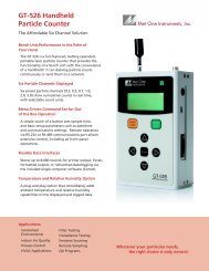
The <strong>AEROCET</strong> <strong>531</strong> is a combined Mass Profiler and Particle Counter in a small, hand<br />
held, battery operated, and completely portable unit.<br />
When used as a particle counter the <strong>AEROCET</strong> <strong>531</strong> provides visual real time count<br />
information in two channels on the LCD display. After one minute, the <strong>AEROCET</strong> <strong>531</strong><br />
displays the two most popular cumulative particle sizes: >0.5µm and >5.0 µm.<br />
When used as a Mass Profiler the <strong>AEROCET</strong> <strong>531</strong> provides a fast indication of particulate<br />
mass concentration per cubic foot of sampled air for the most commonly tested particle<br />
size fractions; PM1, PM2.5, PM7, PM10 and TSP.<br />
The <strong>AEROCET</strong> <strong>531</strong> measurements can compare quite favorably with expensive reference<br />
methods. The <strong>AEROCET</strong> <strong>531</strong> uses the stored particle count data from eight different<br />
particle size ranges and a proprietary algorithm to derive the mass concentration for the<br />
aerosol sample.<br />
The sensor in the <strong>AEROCET</strong> <strong>531</strong> incorporates a long life laser diode, an efficient light<br />
collecting elliptical mirror and unique optics to provide a high concentration limit.<br />
The <strong>AEROCET</strong> <strong>531</strong> contains a 6V Ni-MH Self-contained battery pack, a vacuum pump, an<br />
isokinetic probe, microprocessor electronics, a computer interface and a LCD display all<br />
in one small package.<br />
3.1 Calibration<br />
The <strong>AEROCET</strong> <strong>531</strong> was calibrated at the factory using NIST traceable polystyrene<br />
spheres. When measuring an aerosol that is significantly different than a typical aerosol, a<br />
“K-factor” should be applied to compensate for the error.<br />
The “K-factor” is applied using the AEROComm software.<br />
3.2 Operating Modes<br />
The <strong>AEROCET</strong> <strong>531</strong> can be operated manually or programmed to run continuously.<br />
When used manually, the <strong>AEROCET</strong> <strong>531</strong> is easy to use since the user interface consists of<br />
just a START/STOP button and a MENU button with four arrow selection buttons.<br />
The <strong>AEROCET</strong> <strong>531</strong> can be programmed to continuously take and store samples<br />
unattended. The <strong>AEROCET</strong> <strong>531</strong> will run continuously with its charger plugged in.<br />
The stored measurements can be printed or downloaded to a computer through the<br />
<strong>AEROCET</strong> <strong>531</strong> standard serial interface. Data is output to the serial port at the completion<br />
of a measurement cycle. If the printer port is turned ON then data will be formatted for the<br />
printer, if the printer port is turned OFF data will be formatted for computer storage.<br />
Page 12 of 12 <strong>AEROCET</strong> <strong>531</strong> Operation Manual <strong>AEROCET</strong>-<strong>531</strong>-<strong>9800</strong> <strong>Rev</strong> D.doc
3.3 Operational Feedback<br />
At the end of a manual measurement cycle the instrument will produce a short beep to<br />
signal the operator that the cycle has been completed.<br />
During the measurement cycle the top or time line of the display is replaced with a<br />
progress bar graph and a countdown timer that shows the sample time left in seconds.<br />
3.4 Applications as a particle counter<br />
• Clean room monitoring, verification, and hepa filter testing, FED. STD 209<br />
• Indoor and outdoor (*) air quality studies<br />
• Finding leaks and sources of contamination air ducts and filtration systems<br />
• Hospitals and nursing homes<br />
• Test the efficiency of residential air purifiers and vacuum cleaners<br />
• Check filters for particle leaks<br />
• Epidemiological studies<br />
• Reentrainment studies<br />
3.5 Applications as a particulate mass monitor (**)<br />
• Process control monitoring in sawmills, grain elevators, quarries etc.<br />
• Mines and ore processing plants<br />
• Indoor and outdoor (*) air quality studies<br />
• Finding leaks and sources of contamination air ducts and filtration systems<br />
• Concerned citizen groups that want to do their own air quality studies<br />
• Event monitoring, fence line monitoring<br />
• Epidemiological studies<br />
(*) only with proper protection (e.g. watertight enclosure) and proper precautions (e.g. no<br />
moisture can enter the sample inlet).<br />
(**) if high accuracy is required or atypical aerosols (e.g. Sahara dust) is being sampled<br />
<strong>Met</strong> <strong>One</strong> <strong>Instruments</strong> recommends a K-factor calibration at the sampling location prior to<br />
conducting the measurements.<br />
3.6 Iso-kinetic Sampling<br />
The <strong>AEROCET</strong> <strong>531</strong> comes with an iso-kinetic probe that attaches to its inlet nozzle with<br />
the short piece of Tygon tubing provided.<br />
The iso-kinetic probe helps reduce count errors related to the sample flow velocity and the<br />
aerodynamics of small particles.<br />
<strong>AEROCET</strong>-<strong>531</strong>-<strong>9800</strong> <strong>Rev</strong> D.doc <strong>AEROCET</strong> <strong>531</strong> Operation Manual Page 13 of 13
The iso-kinetic probe should be used for most sampling applications.<br />
When taking a sample of typical indoor or outdoor aerosols the opening of the iso-kinetic<br />
probe should always face upward. The <strong>AEROCET</strong> <strong>531</strong> can be held in your hand or placed<br />
on a flat surface with its display facing towards you.<br />
When sampling in an area that has a constant airflow, such as a clean room, duct, vent or<br />
the downstream side of a filter, always align the opening of the iso-kinetic probe to the air<br />
movement.<br />
The length of the Tygon tubing going from the inlet of the <strong>AEROCET</strong> <strong>531</strong> to the iso-kinetic<br />
probe can be increased if necessary. However, longer lengths can burden the pump and<br />
slow the sample flow rate or cause premature pump failures. Also, count losses, especially<br />
for larger particles, will increase. <strong>Met</strong> <strong>One</strong> <strong>Instruments</strong> recommends to keep the tubing<br />
length as short as possible. The tubing length should never exceed four feet.<br />
The sampling height will affect the <strong>AEROCET</strong> <strong>531</strong> reading. Taking a sample near the floor<br />
can give results several times higher than a sample taken at eye level.<br />
When using the <strong>AEROCET</strong> <strong>531</strong> to analyze a contamination problem be aware that not all<br />
contamination problems are continuous, some are the result of a short-term event or burst<br />
of particles. Locating the source will require taking a number of samples in the same area.<br />
It may be necessary to connect the <strong>AEROCET</strong> <strong>531</strong> to a computer and log data over 24<br />
hours to detect a fast contamination event.<br />
3.7 G3120 Relative Humidity/Temperature Sensor<br />
Relative Humidity and Temperature measurements may be added to the <strong>AEROCET</strong> <strong>531</strong><br />
at any time by plugging in the G3120 Relative Humidity/Temperature Sensor into the plug<br />
on the top of the unit.<br />
The screen will now include actual readings of both measurements; data will now include<br />
the measurements in each data record.<br />
3.8 G3115 Printer<br />
Printed records may be added to the <strong>AEROCET</strong> <strong>531</strong> at any time by plugging in the<br />
optional G3115 printer. This printer is a complete 40 character wide portable printer with<br />
an internal battery and an external AC adapter/charger.<br />
Page 14 of 14 <strong>AEROCET</strong> <strong>531</strong> Operation Manual <strong>AEROCET</strong>-<strong>531</strong>-<strong>9800</strong> <strong>Rev</strong> D.doc
4 <strong>AEROCET</strong> Term Definitions<br />
<strong>AEROCET</strong> <strong>531</strong> commonly used terms are defined in this section.<br />
4.1 Location (or Sample Location)<br />
Each sample event can have a sample location number assigned to it. The sample location<br />
number range is from 001 to 999. Location numbers are required for sampling to begin.<br />
Location numbers are very useful in searching the database.<br />
4.2 Sample (or Sample Type)<br />
Refers to the type of sample Counter or Mass.<br />
A COUNTER sample type consists of two particle sizes—>0.5µm and >5.0µm.<br />
A MASS sample type consists of five mass ranges—PM1, PM2.5, PM7, PM10 and TSP.<br />
4.3 Mode (or Operation Mode)<br />
The mode will be set to either MANUAL or AUTO.<br />
When set to MANUAL operation the START button causes the unit to take one sample and<br />
then stop.<br />
When set to AUTO operation the START button causes the unit to take continuous samples<br />
until the STOP button is pressed.<br />
4.4 Interval (or Sample Interval)<br />
There is a one (1) minute sample interval for a COUNTER sample type.<br />
There is a two (2) minute sample interval for a MASS sample type.<br />
4.5 Event (or Sample Event)<br />
<strong>One</strong> complete sample interval is considered to be a sample event. The <strong>AEROCET</strong> <strong>531</strong><br />
memory can store 3520 events after which the memory must be cleared.<br />
4.6 Printer Mode<br />
At the end of each sample, data is sent to the RS-232 serial port. With the cable provided<br />
you can connect the <strong>AEROCET</strong> <strong>531</strong> to a serial printer or a computer.<br />
With the optional G3115 Printer connected and the Printer mode turned ON the printer will<br />
print a report of each sample event. A sample of the G3115 Printer report is shown in<br />
Appendix A.<br />
When set to OFF the printer output format is a <strong>One</strong>-line style report that may be used for<br />
computer interface. See Appendix A for an example.<br />
<strong>AEROCET</strong>-<strong>531</strong>-<strong>9800</strong> <strong>Rev</strong> D.doc <strong>AEROCET</strong> <strong>531</strong> Operation Manual Page 15 of 15
4.7 Volume Units<br />
When the unit is set in COUNTER mode, the display shows either particles per cubic foot<br />
(FT3) or particles per liter (LITERS).<br />
When the unit is set in the MASS mode the volume is always expressed as mass per cubic<br />
meters.<br />
4.8 Temperature Units<br />
If a <strong>Met</strong> <strong>One</strong> <strong>Instruments</strong> G3120 Relative Humidity/ Temperature Sensor is connected to<br />
the <strong>AEROCET</strong> <strong>531</strong>, the ambient temperature value is displayed in either C (Celsius) or F<br />
(Fahrenheit).<br />
4.9 Low Battery Warning<br />
When the internal battery pack output goes below 5.80 volts DC, a low battery message<br />
(Low Battery!) is displayed on the main sample screen. If the output goes below 5.50<br />
volts the charge battery warning Charge battery! is displayed on the screen (refer to<br />
section 5.10).<br />
Page 16 of 16 <strong>AEROCET</strong> <strong>531</strong> Operation Manual <strong>AEROCET</strong>-<strong>531</strong>-<strong>9800</strong> <strong>Rev</strong> D.doc
5 User Interface<br />
The <strong>AEROCET</strong> <strong>531</strong> has a very simple and user-friendly interface. The following section<br />
describes the user interface in detail. Please read Section 4 for a definition of terms that<br />
are used below.<br />
5.1 Intro Screen<br />
On power up the product intro screen is displayed for 3 seconds. The intro screen displays<br />
the product name and firmware version.<br />
<strong>AEROCET</strong> <strong>531</strong><br />
V1.10<br />
www.metone.com<br />
5.2 Main Screen<br />
There are two main screens. The one displayed depends on the Sample Type selected—<br />
COUNTER or MASS.<br />
5.2.1 Counter Main Screen<br />
This screen shows the results of a COUNTER sample event.<br />
14-APR<br />
09:04:51<br />
001 /ft3 73F<br />
31%<br />
0.5u<br />
173,060<br />
5.0u<br />
710<br />
Line Description<br />
1 If the unit is not taking a sample the current date and time is displayed.<br />
If the unit is taking a sample then a progress bar and seconds remaining is<br />
displayed. <strong>One</strong> sample event takes 60 second to complete.<br />
If you are viewing a previous stored sample then the date and time<br />
represents the time the sample event was stored.<br />
2 First the location number is displayed, then the counter volume units (/ft3<br />
for particles per cubic feet or /l for particles per liter).<br />
If you have an external temperature and humidity sensor plugged in then the<br />
ambient temperature (F or C) and relative humidity values (%) are displayed.<br />
<strong>AEROCET</strong>-<strong>531</strong>-<strong>9800</strong> <strong>Rev</strong> D.doc <strong>AEROCET</strong> <strong>531</strong> Operation Manual Page 17 of 17
3 This line displays the 0.5µm particle size and the associated cumulative<br />
counts of particles per sample event.<br />
4 This line displays the 5.0µm particle size and the associated cumulative<br />
counts of particles per sample event.<br />
Key Description<br />
START<br />
STOP<br />
MENU<br />
ESC<br />
Press this key to start and stop a sample event.<br />
Press this key to go to the main menu.<br />
This key is disabled when the unit is sampling!<br />
ENTER This key is used in conjunction with the left and right arrow keys to navigate<br />
previously taken sample events that are stored in memory.<br />
Pressing this key returns you to the current sample event.<br />
LEFT This key navigates back in time to previously taken sample events.<br />
RIGHT This key navigates forward in time to previously taken sample events.<br />
5.2.2 Mass Main Screen<br />
This screen shows the results of a MASS sample event.<br />
14-APR<br />
09:16:05<br />
001 /m3 73F<br />
31%<br />
PM1 0.000 mg<br />
PM2.5 0.002 mg<br />
Line Description<br />
1 If the unit is not taking a sample the current date and time is displayed.<br />
If the unit is taking a sample then a progress bar and seconds remaining is<br />
displayed. <strong>One</strong> sample event takes 2 minutes (120 seconds) to complete.<br />
If you are viewing a previous stored sample then the date and time<br />
represents the time the sample event was stored.<br />
2 First the location number is displayed and then the volume units for mass<br />
concentration (always cubic meters).<br />
If you have an external temperature and humidity sensor plugged in then the<br />
ambient temperature (F or C) and relative humidity values (%) are displayed.<br />
Page 18 of 18 <strong>AEROCET</strong> <strong>531</strong> Operation Manual <strong>AEROCET</strong>-<strong>531</strong>-<strong>9800</strong> <strong>Rev</strong> D.doc
3 This line displays the mass (mg) per cubic meter for the associated PM<br />
range. Use the up and down arrow keys to scroll through the other PM<br />
ranges (PM1, PM2.5, PM7, PM10, TSP).<br />
4 Same as 3 for the next PM range.<br />
Key Description<br />
START<br />
STOP<br />
MENU<br />
ESC<br />
Press this key to start and stop a sample event.<br />
Press this key to go to the main menu.<br />
This key is disabled when the unit is sampling.<br />
ENTER This key is used in conjunction with the left and right arrow keys to navigate<br />
previously taken sample events that are stored in memory.<br />
Pressing this key returns you to the current sample event.<br />
UP Press the up key to display smaller PM size ranges.<br />
DOWN Press the down key to display larger PM size ranges.<br />
LEFT This key navigates back in time to previously taken sample events.<br />
RIGHT This key navigates forward in time to previously taken sample events.<br />
<strong>AEROCET</strong>-<strong>531</strong>-<strong>9800</strong> <strong>Rev</strong> D.doc <strong>AEROCET</strong> <strong>531</strong> Operation Manual Page 19 of 19
5.3 Main Menu Screen<br />
The main menu screen allows you to navigate to other screens. The menu list contains<br />
items. Use the up and down arrow keys to traverse the menu list.<br />
TAKE SAMPLE<br />
SAMPLE SETUP<br />
RECALL DATA<br />
PRINT DATA<br />
Menu Item Description<br />
TAKE SAMPLE Press ENTER to go to the main screen.<br />
SAMPLE SETUP Press ENTER to go to the SAMPLE SETUP screen.<br />
RECALL DATA Press ENTER to go to the RECALL DATA screen.<br />
PRINT DATA Press ENTER to go to the PRINT DATA screen.<br />
MEMORY Press ENTER to go to the MEMORY screen.<br />
SETTINGS Press ENTER to go to the SETTINGS screen.<br />
CLOCK Press ENTER to go to the CLOCK screen.<br />
Key Description<br />
START<br />
STOP<br />
MENU<br />
ESC<br />
Pressing this key goes to the main screen and starts a sample event.<br />
Pressing this key goes to the main screen.<br />
ENTER Pressing this key goes to the selected menu item.<br />
UP Pressing this key moves the cursor up or scrolls the menu list down.<br />
DOWN Pressing this key moves the cursor down or scrolls the menu list up.<br />
Page 20 of 20 <strong>AEROCET</strong> <strong>531</strong> Operation Manual <strong>AEROCET</strong>-<strong>531</strong>-<strong>9800</strong> <strong>Rev</strong> D.doc
5.4 Sample Setup Screen<br />
The Sample Setup screen allows you to configure the unit for sampling operation. It lets you<br />
identify the location of your sample event; the type of sample; the mode of operation; and<br />
the hold time.<br />
Location: 001<br />
Sample:<br />
COUNTER<br />
Op Mode: MANUAL<br />
HoldTime: 001<br />
Line Description<br />
1 This line displays the location number of the sample event.<br />
The range is from 001 to 999, a value must be entered for correct database<br />
operation.<br />
2 This line displays the sample type selection— COUNTER or MASS.<br />
3 This line displays the operation mode selection — MANUAL or AUTO.<br />
In the MANUAL mode the unit takes one sample and stops.<br />
In the AUTO mode the unit takes samples until the STOP key is pressed.<br />
4 This line displays the HoldTime selection —000 to 999 minutes.<br />
When Op Mode is configured for AUTO mode, then the hold time is the<br />
amount of time between samples. The pump is turned OFF between<br />
samples when the HoldTime is greater than 4 minutes.<br />
Key Description<br />
MENU<br />
ESC<br />
Pressing this key cancels your selections and returns to the main menu.<br />
ENTER Pressing this key saves your selections and returns to the main menu.<br />
UP Pressing this key increments the value in a number field or the next item in a<br />
list field.<br />
DOWN Pressing this key decrements the value in a number field or the next item in a<br />
list field.<br />
LEFT Pressing this key moves the cursor to the left or to the previous field.<br />
RIGHT Pressing this key moves the cursor to the right or to the next field.<br />
<strong>AEROCET</strong>-<strong>531</strong>-<strong>9800</strong> <strong>Rev</strong> D.doc <strong>AEROCET</strong> <strong>531</strong> Operation Manual Page 21 of 21
5.5 Recall Data Screen<br />
The Recall Data screen allows you to find previously taken sample events for display on the<br />
main screen. If the exact time is not known, then enter an approximate time and the<br />
database will locate the sample event closest to the time entered.<br />
After the sample is shown the database may be scrolled using the UP/DOWN arrows to<br />
review the contents of the record or the LEFT/RIGHT arrows to move from sample to<br />
sample.<br />
Recall<br />
Data/Time<br />
20-Apr-01<br />
07:00<br />
Line Description<br />
2 This line displays the date and time selection for recalling a previously taken<br />
sample event. The default date and time is the same as the last used<br />
selection.<br />
Key Description<br />
MENU<br />
ESC<br />
Pressing this key cancels your selection and returns to the main menu.<br />
ENTER Pressing this key saves your selection, finds the nearest sample event time,<br />
and returns to the main screen for display.<br />
UP Pressing this key increments the value in a number field or the next item in a<br />
list field.<br />
DOWN Pressing this key decrements the value in a number field or the next item in a<br />
list field.<br />
LEFT Pressing this key moves the cursor to the left or to the previous field.<br />
RIGHT Pressing this key moves the cursor to the right or to the next field.<br />
Page 22 of 22 <strong>AEROCET</strong> <strong>531</strong> Operation Manual <strong>AEROCET</strong>-<strong>531</strong>-<strong>9800</strong> <strong>Rev</strong> D.doc
5.5.1 Recall Data Records<br />
After the selected data record is recalled the following keys may be used to scroll through<br />
the memory. Records of Mass and Count are not separated in data recall.<br />
Key Description<br />
MENU<br />
ESC<br />
Press this key to go to the main menu.<br />
This key is disabled when the unit is sampling.<br />
ENTER This key is used in conjunction with the left and right arrow keys to navigate<br />
previously taken sample events that are stored in memory.<br />
Pressing this key returns you to the current sample event.<br />
UP Press the up key to display smaller PM size ranges.<br />
DOWN Press the down key to display larger PM size ranges.<br />
LEFT This key navigates back in time to previously taken sample events.<br />
RIGHT This key navigates forward in time to previously taken sample events.<br />
5.6 Print Data Screen<br />
The Print Data screen allows you to select which previously take sample events to print as<br />
a ticket style report. If the exact time is not known, then enter an approximate time and the<br />
database will locate the sample event closest to the time entered.<br />
Type: COUNTER<br />
Location: 001<br />
13-Apr-01<br />
17:15<br />
20-Apr-01<br />
09:39<br />
Line Description<br />
1 This line displays the sample event type selection— COUNTER, MASS or<br />
ALL.<br />
2 This line displays the location identification of the sample event.<br />
The range is from 000 to 999 where 000 will select all locations.<br />
3 This line displays the initial sample event time selection.<br />
4 This line displays the final sample event time selection.<br />
<strong>AEROCET</strong>-<strong>531</strong>-<strong>9800</strong> <strong>Rev</strong> D.doc <strong>AEROCET</strong> <strong>531</strong> Operation Manual Page 23 of 23
Key Description<br />
MENU<br />
ESC<br />
Pressing this key cancels your selection and returns to the main menu.<br />
ENTER Pressing this key saves your selections and starts the printing process. The<br />
printing process status shown on the Printing Status screen<br />
UP Pressing this key increments the value in a number field or the next item in a<br />
list field.<br />
DOWN Pressing this key decrements the value in a number field or the next item in a<br />
list field.<br />
LEFT Pressing this key moves the cursor to the left or to the previous field.<br />
RIGHT Pressing this key moves the cursor to the right or to the next field.<br />
5.6.1 Printing Status Screen<br />
The Printing Status screen shows the progress of the printing process.<br />
Printing Status<br />
Scanning...116<br />
Printing...10<br />
Finished!<br />
Line Description<br />
2 This line displays the number of sample events scanned for printing.<br />
3 This line displays the actual number of sample events printed.<br />
4 Finished! is displayed when the printing processed is complete.<br />
Key Description<br />
MENU<br />
ESC<br />
Pressing this key cancels printing process and returns to the main menu.<br />
Page 24 of 24 <strong>AEROCET</strong> <strong>531</strong> Operation Manual <strong>AEROCET</strong>-<strong>531</strong>-<strong>9800</strong> <strong>Rev</strong> D.doc
5.7 Memory Screen<br />
The Memory screen allows you to clear the memory where the samples events are stored.<br />
Up to 3520 sample events can be stored. When memory is full no further readings can be<br />
taken unit the memory is cleared.<br />
Free: 99%<br />
Samples: 123<br />
Press ENTER to<br />
Clear memory!<br />
Line Description<br />
1 This line displays the percentage of memory free for sample event storage.<br />
2 This line shows the number of sample event currently store in memory.<br />
Key Description<br />
MENU<br />
ESC<br />
Press this key to cancel and return to the main menu.<br />
ENTER Press this key to clear memory<br />
<strong>AEROCET</strong>-<strong>531</strong>-<strong>9800</strong> <strong>Rev</strong> D.doc <strong>AEROCET</strong> <strong>531</strong> Operation Manual Page 25 of 25
5.8 Settings Screen<br />
The Settings screen allows you to selection the counter volume units, the ambient<br />
temperature units, and printer mode.<br />
Counter..<br />
.. Volume:<br />
FT3<br />
Temperature: F<br />
Printer:<br />
OFF<br />
Line Description<br />
2 This line displays the counter volume unit selection— FT3 or LITER.<br />
(FT3 (/ft3) for particles per cubic feet and LITER (/l) for particles per<br />
liter).<br />
3 This line displays the ambient temperature unit selection— F or C.<br />
4 This line displays the Printer mode selection —OFF or ON.<br />
In the ON mode the output is designed for the G3115 printer.<br />
In the OFF mode the printer output is a one line per event style report.<br />
Appendix A shows an example of each report style.<br />
Key Description<br />
MENU<br />
ESC<br />
Pressing this key cancels your selections and returns to the main menu.<br />
ENTER Pressing this key saves your selections and returns to the main menu.<br />
UP Pressing this key increments the value in a number field or the next item in a<br />
list field.<br />
DOWN Pressing this key decrements the value in a number field or the next item in a<br />
list field.<br />
LEFT Pressing this key moves the cursor to the left or to the previous field.<br />
RIGHT Pressing this key moves the cursor to the right or to the next field.<br />
Page 26 of 26 <strong>AEROCET</strong> <strong>531</strong> Operation Manual <strong>AEROCET</strong>-<strong>531</strong>-<strong>9800</strong> <strong>Rev</strong> D.doc
5.8.1 Clock Screen<br />
The Clock screen allows you to set the unit’s real time clock.<br />
Set Clock<br />
Date:14-APR-<br />
2001<br />
Time:09:46:03<br />
Line Description<br />
2 This line displays the date to be set to.<br />
3 This line displays the time to be set to.<br />
Key Description<br />
MENU<br />
ESC<br />
Pressing this key cancels your selections and returns to the main menu.<br />
ENTER Pressing this key sets the clock to your selections and returns to the main<br />
menu.<br />
UP Pressing this key increments the value in a number field or the next item in a<br />
list field.<br />
DOWN Pressing this key decrements the value in a number field or the next item in a<br />
list field.<br />
LEFT Pressing this key moves the cursor to the left or to the previous field.<br />
RIGHT Pressing this key moves the cursor to the right or to the next field.<br />
<strong>AEROCET</strong>-<strong>531</strong>-<strong>9800</strong> <strong>Rev</strong> D.doc <strong>AEROCET</strong> <strong>531</strong> Operation Manual Page 27 of 27
5.9 Memory Full Screen<br />
The Memory Full screen appears when the sample event is full. Full means that 3520<br />
sample events have been stored.<br />
Memory Full!<br />
Press ENTER to<br />
continue...<br />
or ESC to<br />
cancel<br />
Press ESC to return to the main screen.<br />
Pressing ENTER displays the following screen.<br />
Memory Full!<br />
Contents:<br />
to<br />
Printer<br />
Use the up and down arrow keys to select a Contents option of either to PRINTER, to<br />
PC, or DELETE.<br />
Press ESC to cancel your selection and return to the main screen.<br />
If your selection is to PRINTER then pressing ENTER goes to the Print Data screen.<br />
If your selection is DELETE then pressing ENTER goes to the Memory screen.<br />
If your selection is to PC then pressing ENTER goes to the following message screen.<br />
Connect to PC<br />
and run<br />
AEROComm<br />
5.10 Charge Battery Screen<br />
When the battery voltage goes below 5.50 volts this screen appears. All keys are disabled<br />
and this screen will remain until the battery voltage goes above 5.80 volts.<br />
>>> Warning
Charge<br />
battery!!<br />
Battery: 5.48 V<br />
<strong>AEROCET</strong>-<strong>531</strong>-<strong>9800</strong> <strong>Rev</strong> D.doc <strong>AEROCET</strong> <strong>531</strong> Operation Manual Page 29 of 29
6 Serial Interface<br />
The serial interface to the <strong>AEROCET</strong> <strong>531</strong> is a standard 9 pin (DB-9) connector. It is<br />
located on the right hand side of the instrument as shown below. Communication with the<br />
<strong>AEROCET</strong> <strong>531</strong> requires a custom serial cable provided by <strong>Met</strong> <strong>One</strong> <strong>Instruments</strong>.<br />
CAUTION: Standard serial cables will not work and may cause damage to the<br />
instrument if connected.<br />
At the end of a sample, event data are sent to the serial port. The RS-232 serial port is<br />
configured at 9600 baud, 8 data bits, no parity, and 1 stop bit (9600 8N1).<br />
With the cable provided, you could connect the <strong>AEROCET</strong> <strong>531</strong> to a serial printer or a PC<br />
computer.<br />
Below is a description of the DB-9 connector.<br />
Pin Function Comm. Type<br />
1 Chassis Ground<br />
2 TX RS-232<br />
3 RX RS-232<br />
4 DTR RS-232<br />
5 Ground RS-232 & RS-485<br />
6 Not used<br />
7 Not used<br />
8 A RS-485<br />
9 B RS-485<br />
Page 30 of 30 <strong>AEROCET</strong> <strong>531</strong> Operation Manual <strong>AEROCET</strong>-<strong>531</strong>-<strong>9800</strong> <strong>Rev</strong> D.doc
7 Maintenance<br />
7.1 Service Schedule<br />
WARNING: There are no user serviceable components inside this instrument. The covers<br />
on this instrument should not be removed or opened for servicing, calibration or any other<br />
purpose except by a factory authorized person. To do so voids warranty and may result in<br />
exposure to invisible laser radiation that can cause blindness.<br />
Sensor, vacuum pump and filter replacement requires access to the inside of the<br />
<strong>AEROCET</strong> <strong>531</strong>. A factory-authorized person must do this. Contact <strong>Met</strong> <strong>One</strong> <strong>Instruments</strong> for<br />
service information.<br />
Calibrating particle sensors like the one in the <strong>AEROCET</strong> <strong>531</strong> requires specialized<br />
equipment and a skilled technician. <strong>Met</strong> <strong>One</strong> <strong>Instruments</strong>, <strong>Inc</strong>. maintains a calibration<br />
facility for calibrating particle counters according to industry-accepted methods like ASTM<br />
and JIS using NIST traceable standards.<br />
The sensor in the <strong>AEROCET</strong> <strong>531</strong> should be recalibrated on a yearly basis.<br />
7.2 Service Schedule Table<br />
Item To Service Frequency Done By<br />
Zero Count Test Weekly Customer<br />
Flow Rate Test Monthly Customer<br />
Replace Internal Filter Yearly Factory service only<br />
Replace Pump Yearly Factory service only<br />
Replace Battery Pack Yearly Factory service only<br />
Calibrate Sensor Yearly Factory service only<br />
<strong>AEROCET</strong>-<strong>531</strong>-<strong>9800</strong> <strong>Rev</strong> D.doc <strong>AEROCET</strong> <strong>531</strong> Operation Manual Page 31 of 31
7.3 Battery Pack<br />
CAUTION: There are no user serviceable components inside the <strong>AEROCET</strong> <strong>531</strong>. Do<br />
not attempt to change the internal battery pack. The wrong battery pack could cause<br />
serious damage or a fire. Only a factory qualified person should change and properly<br />
dispose of the battery pack.<br />
When the internal battery pack output goes below 5.80 volts DC, a low battery message<br />
(Low Battery!) is displayed on the main sample screen. If the output goes below 5.50<br />
volts the charge battery warning Charge battery! is displayed on the screen (refer to<br />
section 5.10).<br />
To charge the battery pack, connect the AC power cord from the AC to DC converter<br />
module to an AC power outlet. The module is universal and will work with power line<br />
voltages of 100 to 240 volts, 50 to 60 Hz. Take the plug on the end of the cord coming from<br />
the converter module and plug it into the charger input socket on the side of the <strong>AEROCET</strong><br />
<strong>531</strong> just below the power switch. Completely charging a discharged battery pack may take<br />
up to 15 hours.<br />
The battery pack inside the <strong>AEROCET</strong> <strong>531</strong> when fully charged will power the <strong>AEROCET</strong><br />
<strong>531</strong> for about five hours of continuous use. Under normal intermittent or manual operation<br />
however, the battery should last for about 8 hours.<br />
If the <strong>AEROCET</strong> <strong>531</strong> is used on a daily basis, connect the charger at the end of each day.<br />
The battery pack will not be damaged if left connected to the charger over long periods.<br />
If the <strong>AEROCET</strong> <strong>531</strong> is used in an area where AC power is available it is recommended to<br />
leave the charger connected to the <strong>AEROCET</strong> <strong>531</strong>.<br />
If the <strong>AEROCET</strong> <strong>531</strong> is to be stored charge the battery pack. Storing a discharged Ni-MH<br />
battery for any length of time will degrade its performance!<br />
Page 32 of 32 <strong>AEROCET</strong> <strong>531</strong> Operation Manual <strong>AEROCET</strong>-<strong>531</strong>-<strong>9800</strong> <strong>Rev</strong> D.doc
7.4 Zero Count Test<br />
<strong>Met</strong> <strong>One</strong> <strong>Instruments</strong> recommends to periodically perform a zero count test as described<br />
below. False counts caused by air leaks or spurious noise will cause errors that are<br />
especially apparent when sampling relatively clean aerosols.<br />
1. Attach the zero particulate filter (Part Number G3111) to the <strong>AEROCET</strong> <strong>531</strong> inlet<br />
nozzle. The zero filter removes 99.99% of all particles larger than 0.3 micron.<br />
If using another zero filter, that zero filter must be large enough that it does not<br />
create a restriction and load down the small vacuum pump inside the <strong>AEROCET</strong><br />
<strong>531</strong>.<br />
2. Since the air passing through the <strong>AEROCET</strong> <strong>531</strong> is now virtually particle free, the<br />
output should be zero.<br />
3. If using the <strong>AEROCET</strong> <strong>531</strong> in mass mode, select the PM1 range and take a<br />
sample. The result of the 2-minute sample should be zero micrograms.<br />
4. If using the <strong>AEROCET</strong> <strong>531</strong> in count mode, select the 0.5µm range and take a<br />
sample. The result of the 1-minute sample should be zero counts.<br />
<strong>AEROCET</strong>-<strong>531</strong>-<strong>9800</strong> <strong>Rev</strong> D.doc <strong>AEROCET</strong> <strong>531</strong> Operation Manual Page 33 of 33
5. If it does no read zero it could be caused by a leak in the flow path inside the<br />
<strong>AEROCET</strong> <strong>531</strong> or the zero filter is bad. If it is determined that there is a leak, the<br />
<strong>AEROCET</strong> <strong>531</strong> must be sent back to the factory for repair.<br />
7.5 Flow Rate Test<br />
The sample flow rate of 0.1-cfm is set at the factory. Variations in local temperature and<br />
pressure may change this flow rate. Variation in the flow rate will reduce the accuracy of the<br />
instrument.<br />
Testing the flow rate is an easy procedure but it requires a flow meter that is ±3% accurate<br />
at 0.1-cfm. The flow meter must be non-loading to avoid loading the internal flow system.<br />
Most hot wire, ball type, and differential pressure type flow meters are non-loading.<br />
<strong>Met</strong> <strong>One</strong> <strong>Instruments</strong> sells a flow meter (Part number 9801) upon request.<br />
1. To test the flow rate, connect the flow meter to the sample inlet nozzle of the<br />
<strong>AEROCET</strong> <strong>531</strong> using a short piece of flexible 1/8 “ ID tubing, Tygon tubing is a<br />
good choice.<br />
2. Turn on the <strong>AEROCET</strong> <strong>531</strong> and note the flow meter reading. The flow rate should<br />
be 0.1-cfm ±5% (2.83 l/min ±5%).<br />
3. The flow rate can be adjusted by a trimpot located in the lower of the two access<br />
holes in the left side of the <strong>AEROCET</strong> <strong>531</strong> case (see section 2.3). Use the small<br />
screwdriver that came with the <strong>AEROCET</strong> <strong>531</strong> to make the adjustment. Turn the<br />
Page 34 of 34 <strong>AEROCET</strong> <strong>531</strong> Operation Manual <strong>AEROCET</strong>-<strong>531</strong>-<strong>9800</strong> <strong>Rev</strong> D.doc
adjustment pot clockwise to increase the flow and counter-clockwise to decrease<br />
the flow.<br />
4. Monitor the flow rate while adjusting the trimpot.<br />
7.6 Display Contrast Adjust<br />
The LCD display can be adjusted for optimum contrast by a trimpot located in the upper of<br />
the two access holes in the left side of the <strong>AEROCET</strong> <strong>531</strong> case (see section 2.3). Use the<br />
small screwdriver provided to make the adjustment.<br />
Turn the adjustment pot to the desired contrast.<br />
Contrast is affected by temperature; units used outdoors will often require adjustment.<br />
Contrast Adjust<br />
Flow Adjust<br />
<strong>AEROCET</strong>-<strong>531</strong>-<strong>9800</strong> <strong>Rev</strong> D.doc <strong>AEROCET</strong> <strong>531</strong> Operation Manual Page 35 of 35
8 Troubleshooting<br />
WARNING: There are no user serviceable components inside this instrument. The covers<br />
on this instrument should not be removed or opened for servicing, calibration or any other<br />
purpose except by a factory authorized person. To do so voids warranty and may result in<br />
exposure to invisible laser radiation that can cause blindness.<br />
A factory-authorized person should do replacement of the sensor, vacuum pump, filter or<br />
any component inside the <strong>AEROCET</strong> <strong>531</strong>.<br />
Symptom Possible Cause Correction<br />
Does not turn on, no<br />
display<br />
Display turns on but<br />
pump does not<br />
Keypad functions do not<br />
work<br />
Sample result remains at<br />
zero after sampling<br />
Sample result is lower<br />
than normal<br />
Sample result is higher<br />
than normal<br />
Battery pack does not<br />
hold a charge<br />
1. Low battery<br />
2. Defective Battery<br />
1. Low Battery<br />
2. Defective pump<br />
Loose connector or<br />
defective component<br />
inside<br />
1. Pump stopped<br />
2. Laser diode bad<br />
1. Flowrate is low<br />
2. Debris may be stuck<br />
in the inlet nozzle and<br />
blocking the beam<br />
3. Contaminated optics<br />
in sensor<br />
1. Air leak in sensor<br />
2. Noisy laser<br />
1. Defective or worn out<br />
battery pack<br />
2. Defective power<br />
cords<br />
3. Defective charger<br />
module or chords<br />
1. Charge battery 10 hrs<br />
2. Send to service center<br />
1. Charge battery 10 hrs<br />
2. Send to service center<br />
Send to service center<br />
1. Send to service center<br />
2. Send to service center<br />
1. Check flowrate<br />
2. Blow pressurized air into<br />
the nozzle.<br />
Do not put any object<br />
down into nozzle!<br />
3. Send to service center<br />
1. Send to service center<br />
2. Send to service center<br />
1. Send to service center<br />
2. Check with an Ohmmeter<br />
3. Contact your distributor<br />
to get another charger<br />
Page 36 of 36 <strong>AEROCET</strong> <strong>531</strong> Operation Manual <strong>AEROCET</strong>-<strong>531</strong>-<strong>9800</strong> <strong>Rev</strong> D.doc
9 Specifications – <strong>AEROCET</strong> <strong>531</strong><br />
OPERATING PRINCIPLE Counts individual particles utilizing scattered laser light and calculates<br />
the equivalent mass concentration using a proprietary algorithm.<br />
PERFORMANCE<br />
Mass Mode<br />
Mass Concentration Ranges PM1, PM2.5, PM7, PM10, and TSP<br />
Concentration Range 0 - 1 mg/m 3<br />
Sample Time - Mass Mode 2 minutes<br />
Particle Mode<br />
Particle Size Range Two channels - 0.5 and 5.0 µm<br />
Concentration Range 0 - 3,000,000 particles per cubic foot (105,900 particles/L)<br />
Sample Time - Particle Mode 1 minute<br />
Accuracy ± 10%, to calibration aerosol<br />
Sensitivity 0.5 µm @ 2 to 1 peak to valley (JIS), 2 to 1 S/N<br />
Flow Rate 0.1 cfm (2.83 lpm)<br />
ELECTRICAL<br />
Light Source Laser Diode, 5 mW, 780 nm<br />
Power 6V Ni-MH Self-contained battery pack - provides 8 hours<br />
of typical intermittent operation, up to 5 hours continuous use.<br />
Full recharge may take up to 15 hours.<br />
AC Adapter/Charger AC to DC module, 100-240 VAC to 9 VDC @ 350 mA typical<br />
Communications RS-232<br />
Particle Certifications Meets or exceeds CE, ISO, ASTM and JIS international certifications.<br />
Mass Certifications Requires proper use of appropriate K-factors for measured material<br />
INTERFACE<br />
Display 16 character x 4 line LCD<br />
Keyboard 7 key membrane type<br />
PHYSICAL<br />
Size Height = 6.25” Width = 4.0” Thickness = 2.12”<br />
(15.9 cm) (10.2 cm) (5.4cm)<br />
Weight 1.94 lbs - 31 ounces - (0.88 kg)<br />
ENVIRONMENTAL<br />
Operating Temperature 0° to +50° C<br />
Storage Temperature -20° to +60° C<br />
ACCESSORIES<br />
Supplied Operation Manual<br />
Serial Cable (Custom <strong>Met</strong> <strong>One</strong> Part Number 3228)<br />
Communications Software (AEROComm, <strong>Met</strong> <strong>One</strong> Part Number 3289)<br />
AC to DC Converter Module with IEC AC Power Cord<br />
Iso-kinetic Sample Probe<br />
Screwdriver<br />
Carrying Case<br />
Zero Particulate Filter (<strong>Met</strong> <strong>One</strong> Part Number G3111)<br />
Optional RH & Temperature Probe (<strong>Met</strong> <strong>One</strong> Part Number G3120)<br />
Flow <strong>Met</strong>er (<strong>Met</strong> <strong>One</strong> Part Number 61082)<br />
Printer (<strong>Met</strong> <strong>One</strong> Part Number G3115)<br />
<strong>AEROCET</strong>-<strong>531</strong>-<strong>9800</strong> <strong>Rev</strong> D.doc <strong>AEROCET</strong> <strong>531</strong> Operation Manual Page 37 of 37
10 Appendix A<br />
Following are examples of G3115 Printer and Computer <strong>One</strong>-line report styles.<br />
From the Sample Setup screen set the Printer to ON for Printer reports and to OFF for<br />
Computer <strong>One</strong>-line style reports<br />
10.1 Counter Report using G3115 Printer<br />
20-APR-2001 12:52:46<br />
001 24C 40%<br />
0.5u 333,420 /ft3<br />
5.0u 590 /ft3<br />
10.2 Mass Report using G3115 Printer<br />
20-APR-2001 12:56:37<br />
001 24C 40%<br />
PM1 .001 mg/m3<br />
PM2.5 .005 mg/m3<br />
PM7 .010 mg/m3<br />
PM10 .012 mg/m3<br />
TSP .015 mg/m3<br />
10.3 Counter <strong>One</strong>-line Style<br />
20-APR-2001, 13:12:38<br />
Location, 001<br />
Volume, /ft3<br />
Time, 0.5u, 5.0u, AT(C), RH(%)<br />
13:13:39, 267070, 610, 24, 38<br />
13:14:39, 257280, 380, 24, 38<br />
13:15:39, 250800, 660, 25, 38<br />
13:16:39, 254680, 520, 25, 38<br />
13:17:39, 253620, 540, 25, 38<br />
10.4 Mass <strong>One</strong>-line Style<br />
20-APR-2001, 12:57:30<br />
Location, 001<br />
Time, PM1, PM2.5, PM7, PM10, TSP, AT(C), RH(%)<br />
12:59:32, .001, .005, .009, .011, .013, 24, 39<br />
13:01:32, .001, .004, .011, .014, .022, 24, 39<br />
13:03:32, .001, .004, .011, .014, .018, 24, 39<br />
13:05:32, .001, .004, .009, .010, .013, 24, 39<br />
13:07:32, .001, .004, .007, .009, .015, 24, 40<br />
13:09:32, .001, .004, .010, .012, .016, 24, 39<br />
Page 38 of 38 <strong>AEROCET</strong> <strong>531</strong> Operation Manual <strong>AEROCET</strong>-<strong>531</strong>-<strong>9800</strong> <strong>Rev</strong> D.doc
Declaration of Conformity<br />
CE MARKING<br />
Manufacturer’s Name: <strong>Met</strong> <strong>One</strong> <strong>Instruments</strong>, <strong>Inc</strong>.<br />
Manufacturer’s Address: <strong>Met</strong> <strong>One</strong> <strong>Instruments</strong>, <strong>Inc</strong>.<br />
1600 NW Washington Blvd<br />
Grants Pass, Oregon 97526<br />
United States of America<br />
Phone: 541-471-7111<br />
FAX: 541-471-7116<br />
E-Mail: metone@metone.com<br />
Declares, that the product(s):<br />
Product Names:<br />
Model Numbers:<br />
Product Options:<br />
Are in compliance with the following documents:<br />
EMC:<br />
Tom Pottberg<br />
President<br />
January 26, 1999<br />
Particulate Monitor, Aerosol Mass Monitor, Particle<br />
Counter<br />
GT-321, GT-321-1, GT-331, GT-521,<br />
<strong>AEROCET</strong>-<strong>531</strong><br />
All<br />
<strong>Met</strong> <strong>One</strong> <strong>Instruments</strong>, <strong>Inc</strong><br />
1600 NW Washington Blvd.<br />
Grants Pass, Oregon 97526<br />
Telephone 541-471-7111<br />
Facsimile 541-541-7116<br />
Emissions: CISPR 11:1990 / EN 61326-1<br />
Immunity: EN50082-1 / EN 61326-1<br />
Regional Service<br />
3206 Main St. Suite 106<br />
Rowlett, Texas 75088<br />
Telephone 972-412-4715<br />
Facsimile 972-412-4716<br />
<strong>AEROCET</strong>-<strong>531</strong>-<strong>9800</strong> <strong>Rev</strong> D.doc <strong>AEROCET</strong> <strong>531</strong> Operation Manual Page 39 of 39