GER3688B - GE Generators - An Overview - GE Energy
GER3688B - GE Generators - An Overview - GE Energy
GER3688B - GE Generators - An Overview - GE Energy

You also want an ePaper? Increase the reach of your titles
YUMPU automatically turns print PDFs into web optimized ePapers that Google loves.
FluId<br />
Figure 13. LM6000<br />
Relative<br />
Spectfic<br />
HEat<br />
Relative<br />
Denstty<br />
Relative<br />
Practical<br />
Vol Flow<br />
RDC26475-2 GO2A-00.044<br />
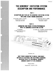
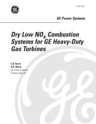
Figure 15. Hydrogen-cooled generator<br />
Approx.<br />
Rel Heat<br />
Removal<br />
Abihty<br />
1 1.0 1 1.0 1 10 I 1.0 )<br />
Hydrogen 30 pslg (2.07 bar) 14.36 0.21 10 3.0<br />
Hydrogen 45 psig<br />
(3.10 bar) 14.36 0.26 IO 4.0<br />
Water 4.16 1000.0 0 012 50.0<br />
GT21022A<br />
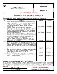
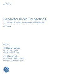
Figure 14. Air, hydrogen, water heat removal<br />
comparison<br />
MVA at 0.8 pf. In 1993, a 160 MVA, 50-Hz air-<br />
cooled generator, to be used primarily with the<br />
frame 9E gas turbine, will be tested as well.<br />
HYDRO<strong>GE</strong>N-COOLED<br />
<strong>GE</strong>NERATORS<br />
As the rating of steam turbines rose in the<br />
1930-1950 time frame, it became clear that in<br />
order to keep the size, weight, ability to ship and<br />
cost of a generator within reason, a more optimal<br />
cooling medium needed to be used. Hence the<br />
introduction of hydrogen.<br />
How well the armature winding of a generator<br />
is cooled has a significant influence on the overall<br />
size of a synchronous generator. The cooling of<br />
the armature winding is dependent on a number<br />
of factors: cooling medium (air, hydrogen, water) ;<br />
insulation thickness; and overall electrical losses<br />
(12R + load loss). As Figure 14 shows, relative heat<br />
removal capability improves from air to hydrogen,<br />
with increased hydrogen pressure, and even more<br />
significant with the use of water cooling.<br />
Conventional hydrogen cooling can be utilized on<br />
generators rated approximately 300 MVA and<br />
9<br />
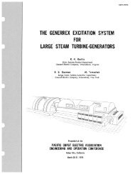
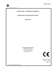
Figure 16.7F generator<br />
RDC26126.21-3<br />
below, while direct water cooling of armature<br />
windings is applied to units above 250 MVA. This<br />
division results from design optimization. While it<br />
is possible to apply water cooling on machines<br />
rated below 250 MVA, the cost/performance ben-<br />
efit suffers. Water cooling adds manufacturing<br />
complexity, as well as requires the need for an<br />
auxiliary water cooling and deionizing skid, plus<br />
associated piping, control and protection features.<br />
At higher ratings, the cost of this complexity is off-<br />
set by the advantage of producing a generator of<br />
significantly smaller size than a comparable con-<br />
ventionallycooled generator.<br />
Hydrogen-cooled generator construction<br />
(Figure 15)) except for the frame, is very similar<br />
to that of air-cooled generators. The stator slot<br />
and end winding support designs are essentially<br />
like those shown in Figures 6 and ‘7. Most designs<br />
use direct radial flow cooling similar to that<br />
shown in Figure 10. The stator frame, on the<br />
other hand, because of the need to contain 30<br />
psig (2.07 bar) to 45 psig (3.10 bar) hydrogen,<br />
uses thick plate cylindrical construction. End<br />
shields are appropriately more rugged, and con-<br />
tain a hydrogen seal system to minimize leakage.<br />
Conventional hydrogen cooling, while available<br />
<strong>GE</strong>R-3688B