GER3688B - GE Generators - An Overview - GE Energy
GER3688B - GE Generators - An Overview - GE Energy
GER3688B - GE Generators - An Overview - GE Energy

Create successful ePaper yourself
Turn your PDF publications into a flip-book with our unique Google optimized e-Paper software.
GT17109<br />
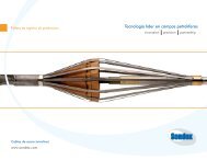
Figure 2 1. Armature bar restraint in stator slot<br />
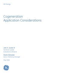
Forces on Stator Winding-s<br />
There are two sources of force on the stator<br />
windings: high-level, short-duration transient<br />
forces due to system or misoperation faults, as well<br />
as those that result from normal load currents<br />
and load cycling.<br />
Figure 20 charts frequency of occurrence against<br />
relative magnitude for these forces. Each type of<br />
force requires careful consideration during the<br />
design process. High-level fault currents can cause<br />
very high forces, which will cause major winding<br />
damage if not suitably restrained. Load cycling, and<br />
the thermal expansion which accompanies it, is a<br />
daily event that causes expansion and contraction<br />
of the entire windings. If components are not suit-<br />
ably designed, or if windings are unduly restrained<br />
in the axial direction, lowcycle fatigue damage may<br />
occur. Finally, the electromagnetic forces at twice<br />
system frequency due to normal load currents may<br />
cause fretting or highcycle fatigue of components,<br />
particularly if a component has a mechanical reso<br />
GT17110<br />
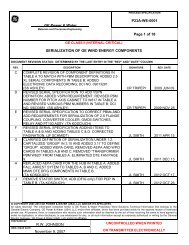
Figure 22. Stator and winding support cross<br />
section<br />
11<br />
nance close to double frequency.<br />
These forces require the design engineer to<br />
closely examine the detail design of the endwind-<br />
ing and stator slot sections.<br />
Stator Slot Support System<br />
The key elements of the stator-slot support<br />
system design (Figure 21) are:<br />
Careful assembly of the stator core to ensure<br />
a uniform slot dimension and avoid “high<br />
areas.”<br />
Use of side ripple springs full length along<br />
each bar to ground the bar armor to the slot<br />
and provide permanent friction damping<br />
against tangential and radial motion.<br />
A top-of-slot, radial force wedge designed to<br />
securely hold the armature bars down to the<br />
bottom of the slot, preventing potential<br />
destructive bar motion.<br />
Freedom for axial movement to accommodate<br />
thermal expansion without component stress.<br />
Endwinding Support Structure<br />
Because the endwindings are suspended<br />
beyond the core, shortcircuit or faulty synchroniz-<br />
ing current forces are much more difficult to<br />
restrain than those in the stator slots. In addition,<br />
the structure itself has many more “degrees of free-<br />
dom” complicating the process of avoiding detri-<br />
mental resonant frequencies. As with the stator slot<br />
support system, the endwinding support system for<br />
a watercooled armature design is more complex<br />
than that for a conventionally-cooled winding.<br />
However, each of the support systems evolved from<br />
the same heritage, and both have provided<br />
extremely reliable service since their introduction.<br />
The advanced TetralocTM endwinding support<br />
system (Figure 22) is used on all water-cooled<br />
designs and features:<br />
l A support basket consisting of axial supports,<br />
supported from the stator flange, and contin-<br />
uous circumferential epoxy fiberglass rings.<br />
l Glass filament ties to secure the armature<br />
bars to the fiberglass rings.<br />
l Conformable, resin-impregnated, between-<br />
bar blocking to maintain bar spacing and<br />
provide mechanical support.<br />
Rotor Electrical Design<br />
The generator rotor contains the field windings<br />
that produce the magnetic flux, which, in turn,<br />
produces the stator current and voltage. Proper<br />
cooling of the field winding is another challenge<br />
<strong>GE</strong>R-3688B