Downloads - New Eagle
Downloads - New Eagle
Downloads - New Eagle

You also want an ePaper? Increase the reach of your titles
YUMPU automatically turns print PDFs into web optimized ePapers that Google loves.
CONTACT INFORMATION<br />
MECHATRONIC CONTROL SOLUTIONS<br />
Let us know how we can help!<br />
To contact us by telephone, please call 877.234.1410<br />
To request a quote, please contact quotes@neweagle.net<br />
For <strong>New</strong> <strong>Eagle</strong> orders, please contact orders@neweagle.net<br />
TRAINING SUPPLEMENT<br />
Agenda 2<br />
Software Requirements 3<br />
Training Project System Overview 4<br />
Training Project Block Diagram 5<br />
Controller I/O Acronyms 6<br />
Controller Hardware Layout 8<br />
Product and tools support<br />
http://www.neweagle.net/support/wiki/<br />
support@neweagle.net<br />
Vardec Parameters 9<br />
Calibration Management 12<br />
Analog Input 14<br />
PWM Output 15<br />
Fault Management 16
Morning<br />
Afternoon<br />
Phone: 877.234.1410 support@neweagle.net www.neweagle.net<br />
Basic MotoHawk Training Agenda<br />
DAY 1 DAY 2 DAY 3<br />
Introduction<br />
Software installation<br />
Basics of MATLAB/Simulink & MotoHawk<br />
Simple Simulink model<br />
First build, kit setup, and flash<br />
Basics of MotoTune<br />
Triggers<br />
I/O<br />
Calibrations, probes, & overrides<br />
Throttle project: I/O<br />
Fault management<br />
Throttle project: Faults<br />
Throttle project: PID control<br />
Data storage<br />
Throttle project: Data storage<br />
CAN<br />
Throttle project: CAN<br />
Libraries<br />
Components<br />
<strong>New</strong> <strong>Eagle</strong> hardware & software offerings<br />
Questions<br />
Evaluation<br />
MotoHawk Training Supplement - Page 2
Software Requirements<br />
Welcome to MotoHawk training! Presented by <strong>New</strong> <strong>Eagle</strong>, this<br />
three day course will train you to create a real-world application<br />
with Simulink and MotoHawk, program a module, and calibrate<br />
in real-time using MotoTune. But first things first, let’s make sure<br />
you have the correct software on your laptop.<br />
The training requires several software installations involving a<br />
somewhat complex compatibility maze. The following lists the<br />
software requirements and any relevant compatibility notes.<br />
Please install software in the order listed PRIOR to training.<br />
Windows<br />
If Windows installation is 64bit, MotoHawk 2010aSP0 or later is required<br />
MathWorks<br />
Required installations*<br />
- MATLAB**<br />
- Simulink<br />
- Real Time Workshop<br />
- Real Time Workshop Embedded Coder<br />
- Stateflow (optional, but highly recommended)<br />
- Stateflow Coder (optional, but highly recommended)<br />
*Required before training (MathWorks distributes trial downloads and licenses)<br />
**If MATLAB installation is 64bit, MotoHawk 2010bSP0 or later is required<br />
With the installations above complete, you’re system is prepared to<br />
work with the MotoHawk Tool Suite.<br />
The necessary software for the MotoHawk tools and a temporary<br />
license will be provided at training.<br />
Phone: 877.234.1410 support@neweagle.net www.neweagle.net<br />
The following software will be installed DURING training.<br />
MotoHawk<br />
MotoServer/MotoTune*<br />
*With MotoHawk 2010aBeta6 and later, MotoServer/MotoTune 8.13.7.120 or later is required<br />
*With MotoHawk 2009bBeta1 and later, MotoServer/MotoTune 8.13.7.87 or later is required<br />
GCC (compiler)*<br />
*MotoHawk 2009bBeta2 or later is required<br />
CANKing<br />
MotoHawk Training Supplement - Page 3
Training Project System Overview<br />
Phone: 877.234.1410 support@neweagle.net www.neweagle.net<br />
MotoHawk Training Supplement - Page 4
TO<br />
COMPUTER<br />
Training Project Block Diagram<br />
KEY<br />
SWITCH<br />
BUTTON<br />
USB-<br />
TO-<br />
CAN<br />
BOOT KEY<br />
(IF NEEDED)<br />
FROM<br />
BATTERY +<br />
A<br />
F<br />
C<br />
D<br />
J<br />
K<br />
A<br />
B<br />
E<br />
JUNCTION BOX<br />
A<br />
B<br />
E<br />
F<br />
G<br />
H<br />
J<br />
K<br />
C<br />
D<br />
J<br />
K<br />
W49, RED<br />
30A FUSE<br />
W56, RED<br />
W61, RED<br />
NORMAL<br />
5A FUSE<br />
BOOT<br />
5A FUSE<br />
W64, RED<br />
TERMINATION<br />
RESISTOR<br />
W55, RED<br />
W60, RED<br />
W62, RED<br />
W63, RED<br />
Phone: 877.234.1410 support@neweagle.net www.neweagle.net<br />
APP<br />
TPS<br />
W59, RED<br />
W57, BLK<br />
W46, RED<br />
W32, BRN-WHT<br />
W47, BLK-YEL<br />
W44, WHT<br />
W45, BLU<br />
W31, YEL<br />
W30, BRN<br />
W38, ORG<br />
W37, GRN<br />
W48, PPL-YEL<br />
W25, BLK-ORG<br />
W29, RED-PNK<br />
W28, DKBLU-PNK<br />
W40, GRN-RED<br />
W39, GRN-YEL<br />
W26, TAN<br />
W27, YEL<br />
W34, ORG-BLK<br />
W35, BLU-BLK<br />
W10, GRY<br />
W11, DKBLU<br />
W09, TAN-LTBLU<br />
W12, DKBLU-WHT<br />
W33, GRY-RED<br />
W36, WHT-ORG<br />
W42, PPL<br />
W43, TAN-PPL<br />
W15, BLK-YEL<br />
W06, BLK-RED<br />
W03, YEL-BLK<br />
W19, ORG<br />
B-22<br />
B-08<br />
B-23<br />
B-20<br />
B-21<br />
B-07<br />
B-06<br />
B-14<br />
B-13<br />
B-24<br />
B-01<br />
B-05<br />
B-04<br />
B-16<br />
B-15<br />
B-02<br />
B-03<br />
B-10<br />
B-11<br />
A-10<br />
A-11<br />
A-09<br />
A-12<br />
B-09<br />
B-12<br />
B-18<br />
B-19<br />
A-15<br />
A-06<br />
A-03<br />
A-19<br />
BATT<br />
ECUP<br />
STOP<br />
CAN1+<br />
CAN1-<br />
CAN2+<br />
CAN2-<br />
CAN3+<br />
CAN3-<br />
XDRP<br />
XDRG<br />
DG1M (10KPU), VR1+ or DG1M (51K1PD)<br />
AN17M (220KPD), VR1-<br />
DG2M (10KPU), VR2+ or DG2M (51K1PD)<br />
AN18M or DG8M (3KPD), VR2-<br />
AN1M (220KPD, 100PU)<br />
AN2M (220KPD, 100PU)<br />
AN3M (220KPD, 1KPU)<br />
AN4M (220KPD, 1KPU)<br />
AN5M (220KPD, 51K1PD)<br />
AN6M (220KPD, 51K1PD)<br />
AN7M (220KPD, 51K1PD)<br />
AN8M (220KPD)<br />
AN9M (220KPD)<br />
AN10M (220KPD)<br />
AN11M or DG3M (220KPD, 1KPU)<br />
AN12M or DG4M (220KPD, 1KPU)<br />
AN13M or DG5M (3KPD)<br />
AN14M or DG6M (3KPD)<br />
AN15M (220KPD, 1KPU)<br />
AN16M or DG7M (3KPD)<br />
GCM-0563-048-0801<br />
GCM-0563-048-0802<br />
DRVGA<br />
DRVGB<br />
DRVGC<br />
HSO1<br />
HSO2<br />
DRVPA<br />
DRVPB<br />
MPRD<br />
LSO1<br />
LSO2<br />
LSO3<br />
LSO4<br />
LSO5<br />
Connected to B-23, LSO6<br />
LSO7<br />
H1+<br />
H1-<br />
A-16<br />
A-24<br />
B-17<br />
A-04<br />
A-18<br />
A-20<br />
A-21<br />
A-22<br />
A-02<br />
A-13<br />
A-07<br />
A-08<br />
A-14<br />
A-05<br />
A-23<br />
A-01<br />
A-17<br />
W16, BLK-WHT<br />
W24, BLK-WHT<br />
W41, BLK-GRN<br />
W04, WHT<br />
W18, PNK-BRN<br />
W20, ORG-WHT<br />
W21, BLK-BLU<br />
W22, YEL-PPL<br />
W02, PNK-ORG<br />
W13, WHT-LTBLU<br />
W07, YEL-ORG<br />
W08, LTBLU<br />
W14, WHT-BLK<br />
W05, WHT-DKBLU<br />
W23, RED-BLK<br />
W01, PNK-LTBLU<br />
W17, PNK-PPL<br />
W58, BLK<br />
TO<br />
BATTERY -<br />
MAIN POWER<br />
RELAY<br />
W53, RED W51, RED<br />
W54, RED<br />
FUEL<br />
INJECTOR<br />
ETC<br />
MOTOR<br />
W52, RED<br />
MotoHawk Training Supplement - Page 5
Controller I/O Acronyms<br />
GCM-0563-048-0801<br />
GCM-0563-048-0802<br />
Acronym : …Literally Means : Other Notations : General Notes :<br />
BATT BATTery ~ 180mA at 13.8V (module only, no external loads); connected directly<br />
to battery+; low-current power to analog/digital core of module; allows<br />
controlled shutdown<br />
ECUP ECU Power KEYSW, WAKE ~ 5mA at 13.8V; derived (through switch) from battery+; ”wake-up”<br />
signal to module to initiate execution of software algorithm (when power<br />
removed, operations continue until software commands a shutdown)<br />
STOP Emergency STOP ESTOP when asserted, disables the main power relay through hardware (on<br />
other modules, may disable engine-related outputs such as EST and<br />
FUELP); input for boot mode signal<br />
DRVPx DRiVer Power DRVPWRx through MPR, provides battery+ to actuators; internally provides power to<br />
H-bridges (allows controlled shutdown on modules without BATT)<br />
DRVGx DRiVer Ground GNDx, PWRGRNDx connected directly to battery-<br />
XDRPx TRANSDuceR Power XDRPWRx 300mA maximum; 5V reference for sensors<br />
XDRGx TRANSDuceR Ground XDRGNDx internal connection to DRVG; low reference for sensors<br />
ANxM ANalog sensor input Monitor ANx has a pull-up and/or pull-down internal resistor; time constant through<br />
an internal capacitor and additional internal resistor<br />
DGxM DiGital sensor input Monitor DGx same as analog sensor input monitor, but may also resolve frequency<br />
VRx+, VRx- Variable Reluctance sensor input typically used to resolve frequency (on other modules, used to resolve<br />
engine crankshaft position)<br />
MPRD Main Power Relay Driver controls the main power relay<br />
LSOx Low-Side driver Output LSDx connection to DRVG through transistor; PWM capable<br />
HSOx High-Side Output HSDx connection to DRVP through power switch; PWM capable<br />
Hx+, Hx-, H-Bridge output HBxA, HBxB, ETCx,<br />
HBRIDGExA, HBRIDGExB<br />
on some modules, can also be operated independently as low-side or<br />
high-side driver outputs<br />
CANx+, CANx- Controller Area Network communication CAN 2.0B protocol<br />
Phone: 877.234.1410 support@neweagle.net www.neweagle.net<br />
MotoHawk Training Supplement - Page 6
Controller I/O Acronyms (continued)<br />
Common Acronyms<br />
Found On Other Modules:<br />
Acronym : …Literally Means : Other Notations : General Notes :<br />
GNDREF GrouND REFerence ground reference signal<br />
CNK+, CNK- CraNKshaft encoder sensor input CNKVR+, CNKVR-,<br />
CNKDG<br />
Phone: 877.234.1410 support@neweagle.net www.neweagle.net<br />
typically used to resolve engine crankshaft position (with variable<br />
reluctance and/or digital sensor inputs)<br />
CAM+, CAM- CAMshaft encoder sensor input CAMDG typically used to resolve engine camshaft position (with variable<br />
reluctance and/or digital sensor inputs)<br />
SPDx, SPD- SPeeD (frequency) sensor input SPEEDx typically used to resolve frequency (with variable reluctance and/or<br />
digital sensor inputs)<br />
EKxP, EKxN Engine Knock sensor input KNKx+, KNKx- used with wide-range piezoelectric knock sensors<br />
EGOxP, EGOxN Exhaust Gas Oxygen sensor input dual differential amplifier targeted at lambda oxygen sensor signal<br />
processing<br />
HEGOx Heated Exhaust Gas Oxygen sensor input O2x+, O2x- used with switching type oxygen sensor (heated or unheated)<br />
LSUxUN, LSUxIA, LSUxIP,<br />
LSUxVM<br />
Lambda Sensing Unit sensor input used with the Bosch CJ125 exhaust gas oxygen sensor<br />
INJx fuel INJector driver output FINJx, FIx low-side output to drive high-impedance fuel injector<br />
ESTx Electronic Spark Timing output 5V signal to drive logic level (“”smart””) ignition coil;<br />
on some modules, may be used as additional analog inputs<br />
EST RTN EST ReTurN reference level for logic level (“smart”) ignition coils<br />
FUELPR FUEL Pump Relay FUELP low-side output to drive fuel pump relay<br />
BATT_OUT BATTery OUT supply voltage for external input devices<br />
TACH_LINK TACHometer output or LINK interface tachometer output or LINK serial interface<br />
SCL+, SCL- Serial Communication Link RS-485A, RS-485B RS485 serial communication link<br />
ISO9141K, ISO9141L ISO9141 communication link ISO9141 communication link<br />
MotoHawk Training Supplement - Page 7
Controller Hardware Layout<br />
Phone: 877.234.1410 support@neweagle.net www.neweagle.net<br />
Component Descriptions<br />
Inputs Analog, discrete,<br />
frequency, crank/cam and<br />
corresponding resource<br />
circuitry<br />
A/D Converter For analog inputs, converts<br />
voltage into ADC’s<br />
MIOS Modular Input/Output<br />
System, asychronous (nonangle-based)<br />
operations only<br />
TPU Time Processing Unit,<br />
synchronous (angle-based) or<br />
asynchronous operations<br />
CAN Controller Area Network<br />
communication<br />
Serial RS485 serial communication<br />
(RS232 on some modules)<br />
RAM Random Access Memory,<br />
volatile variable, stack, and<br />
heap storage<br />
Flash Constant data and<br />
executable code<br />
Serial EEPROM Electrically-Erasable<br />
Programmable Read-Only<br />
Memory; nonvolatile variable<br />
storage<br />
External RAM Select modules only; same<br />
as RAM above (but slower)<br />
Parallel<br />
EEPROM<br />
constant variable storage,<br />
calibration in development<br />
units only<br />
Outputs Circuitry to drive the following<br />
outputs: discrete, PWM,<br />
engine-specific (fuel injector,<br />
EST), H-bridge, low-side<br />
output, high-side output<br />
MotoHawk Training Supplement - Page 8
Vardec Parameters<br />
Vardec — a global variable declaration.<br />
Vardecs are unique by name and are created by numerous MotoHawk<br />
blocks, such as calibrations, probes, look-up tables, and data definitions.<br />
Below are common mask parameters found with MotoHawk vardec blocks.<br />
Note that not all of the mask parameters below are available for each vardec.<br />
Name — The name of the vardec.<br />
Must be unique among all other vardecs in a MotoHawk model.<br />
Initial Value — The initial value of the variable. The dimensions of the<br />
initial value set the size of the variable. For instance, if the initial value is<br />
set as zeros(5), the variable is a 5x5 matrix. If the initial value is set as [0<br />
1 2 3], the variable is a vector of length 4. Or, if the initial value is set as<br />
½, the variable is a scalar.<br />
Behavior — The display and storage behavior of the variable.<br />
Storage Class — The storage class of the variable.<br />
Output Data Reference — Option to output a reference signal pointing<br />
to the variable. For instance, this outport signal could be connected to a<br />
MotoHawk Data Read block to expose that variable for use downstream in<br />
the application.<br />
MotoTune Window — Option to set the variable as a calibration (i.e.,<br />
appear in a .cal file) or a display (i.e., appear in a .dis file).<br />
Name Source — Option to define the vardec name by the Parameter<br />
(using Name mask parameter above) or Output Wire Name (using the<br />
name of the output wire).<br />
Data Source — Option on how to define the data source. Lookup By<br />
Name uses the Data Name mask parameter, Input Reference Signal<br />
provides a reference inport, Lookup By Name In Structure uses the Data<br />
Name mask parameter in conjunction with the name of the structure, and<br />
Lookup By Name In Structure Via Reference uses a reference inport in<br />
conjunction with the name of the structure.<br />
Data Structure — The dimensional structure of the variable.<br />
If Vector or Matrix is selected, additional options are provided to Read/<br />
write scalar from location by index (zero-based) or Read entire data<br />
structure at once; if the latter is selected, the dimensions of the vector/<br />
matrix must be explicitly specified.<br />
Phone: 877.234.1410 support@neweagle.net www.neweagle.net<br />
Behavior Description<br />
Calibration On a development module, stored in parallel EEPROM.<br />
On a production module, stored as a constant in flash (can only be<br />
changed through reflash).<br />
Viewed as calibration in MotoTune.<br />
Display Stored in RAM.<br />
Viewed as display variable in MotoTune.<br />
Calibration NV Stored in serial EEPROM (shadowed in RAM).<br />
Viewed as calibration in MotoTune.<br />
Display NV Stored in serial EEPROM (shadowed in RAM).<br />
Viewed as display variable in MotoTune.<br />
Storage Class Description<br />
Constant On a development module, stored in parallel EEPROM.<br />
On a production module, stored as a constant in flash (only can be<br />
changed through reflash).<br />
Volatile Stored in RAM.<br />
NonVolatile Stored in serial EEPROM (shadowed in RAM).<br />
Fixed NonVolatile Stored in serial EEPROM (shadowed in RAM) (attempts to maintain over<br />
programming cycle).<br />
MotoHawk Training Supplement - Page 9
Vardec Parameters (continued)<br />
Output Data Type — The data type of the signal originating from the<br />
output port. The Inherit from ‘Default Value’ option evaluates the data type<br />
of the default value to set the block’s data type (e.g., the data type can be<br />
explicitly specified as uint8 by entering the default value as uint8(100)).<br />
The Inherit via back propagation sets the data type to that governed (where<br />
applicable) by other connected Simulink/MotoHawk blocks. Otherwise,<br />
the data type can be explicitly specified as an integer or floating point data<br />
type.<br />
Read and Write Access Level — Option to set security level on read/write<br />
access from MotoTune (1 is the lowest, 4 is the highest security level). The<br />
user’s security level is the minimum of the MotoServer communication<br />
port setting and the license dongle setting. A security level of 4 is required<br />
to create a new MotoTune online calibration; however, any security level will<br />
allow the creating of a new MotoTune online display.<br />
After opening (previously created) MotoTune calibrations/displays,<br />
individual calibration/display variables will allow read/write access if the<br />
security level set in the MotoHawk block is equal to or less than the user’s<br />
security level.<br />
Note that, for variables with both read and write access, the read access level must be<br />
equal to or less than the write access level.<br />
Use uploaded calibration values from MotoTune<br />
Option to use or ignore values input from MotoTune.<br />
View Value As — Option as to how the engineering value is displayed in<br />
MotoTune. The Number option displays the engineering value numerically.<br />
The Enumeration option displays an associated enumeration; for example,<br />
if the Enumeration (Cell String, or Struct) is {‘State 1’, ‘State 2’, ‘State 3’}<br />
and the numeric engineering value is 1, then “State 2” will be displayed in<br />
MotoTune.<br />
Note that this option is only applicable with Boolean or integer data types and that the<br />
enumeration definition indices are zero-based.<br />
The Text option displays the ASCII character interpretation of the value;<br />
for example, if the engineering value is a vector with values [35 63 106],<br />
MotoTune will display “#?j”.<br />
This option may only be used with a uint8 data type.<br />
Show Vectors As — Option to display (in MotoTune) the vector as a Wide<br />
Row or a Tall Column.<br />
This is only applicable if the variable is a vector.<br />
Phone: 877.234.1410 support@neweagle.net www.neweagle.net<br />
Data Type Size (bytes) Min. Max. Resolution<br />
double 8 -inf inf depends on magnitude<br />
single 4 -inf inf depends on magnitude<br />
int8 1 -128 127 1<br />
uint8 1 0 254 1<br />
int16 2 -32768 32767 1<br />
uint16 2 0 65535 1<br />
int32 4 -2147483648 2147483647 1<br />
uint32 4 0 4294967295 1<br />
boolean 1 0 1 1<br />
reference 2 for S12,<br />
4 for other<br />
n/a n/a n/a<br />
struct inherits data types from fields in structure declaration<br />
struct container dependent on number of structure instances associated with container;<br />
inherits data types from fields in structure declaration<br />
struct reference 2 for S12,<br />
4 for other<br />
n/a n/a n/a<br />
MotoHawk Training Supplement - Page 10
Vardec Parameters (continued)<br />
Help Text — A description of the variable to be displayed in MotoTune.<br />
Enclose the help text between single quotation marks.<br />
Units — The engineering units of the variable to be displayed in MotoTune.<br />
Enclose the units between single quotation marks. For example, the help<br />
text and units for a group of calibrations may appear in MotoTune as:<br />
Row Header Enumeration (Cell String, or Struct) — Headings for the<br />
rows of the variable to be displayed in MotoTune. A row header is only<br />
applicable if the variable is a column vector or a matrix (i.e., the heading is<br />
for the rows). Specify the headings in a cell string format.<br />
Column Header Enumeration (Cell String, or Struct) — Headings<br />
for the columns of the variable to be displayed in MotoTune. A column<br />
header is only applicable if the variable is a row vector or a matrix (i.e., the<br />
heading is for the columns). Specify the headings in a cell string format.<br />
For example, if the row header enumeration is specified as {‘Row 1’, ‘Row<br />
2’, ‘Row 3’} and the column header enumeration is specified as {‘Col 1’,<br />
‘Col 2’, ‘Col 3’}, the variable will be seen in MotoTune as the following:<br />
Phone: 877.234.1410 support@neweagle.net www.neweagle.net<br />
Minimum Value — The minimum allowable value for the variable. This will prevent a user<br />
from entering an out-of-range value from MotoTune.<br />
This value is in engineering units (i.e., after the gain, offset, and exponent have been applied).<br />
Maximum Value — The maximum allowable value for the variable. This will prevent a user<br />
from entering an out-of-range value from MotoTune.<br />
This value is in engineering units (i.e., after the gain, offset, and exponent have been applied).<br />
Precision — The precision of the variable as displayed in MotoTune. Enclose the precision<br />
between single quotation marks using the syntax ‘0.DecimalPlaces’. For instance, if the<br />
variable has a value of 98.76543 and the precision is ‘0.3’, the value would appear in<br />
MotoTune as 98.765. The default precision of ‘’ will display 2 decimal places.<br />
Gain — The gain applied to the raw value to calculate the engineering value as observed in<br />
MotoTune.<br />
Offset — The offset applied to the raw value to calculate the engineering value as observed<br />
in MotoTune.<br />
Exponent — The exponent applied to the raw value to calculate the engineering value as<br />
observed in MotoTune. The MotoTune gain, offset, and exponent are applied according to the following:<br />
(engineering value as displayed in MotoTune) = ( Gain * (raw value) )^Exponent + Offset<br />
MotoTune Group String — The folder name and hierarchy that contains the variable in<br />
MotoTune. Enclose the MotoTune group string between single quotation marks, and use the<br />
| character to delineate subfolder structure.<br />
For example, if the MotoTune group string for Calibration1 is specified as ‘Group1 |<br />
Subgroup1 | Subsubgroup’, the variable will be found in MotoTune in the following:<br />
MotoHawk Training Supplement - Page 11
Calibration Management<br />
Calibration Management<br />
There are several methods of calibration management<br />
within the MotoHawk and MotoTune software.<br />
A. Maintain the calibrations in the model. (Optional)<br />
The engineer inserts correct calibrations into the default values of the<br />
vardec blocks. Benefits of this approach are:<br />
the engineer can easily run the model in simulation and perform<br />
software-in-the-loop development.<br />
maintaining the calibrations in the model means the application<br />
is ready to run with simply a model build; no additional steps are<br />
necessary.<br />
The downsides to this approach are:<br />
online calibration changes need to be manually and tediously<br />
transferred into the MotoHawk model.<br />
this approach neglects the useful calibration management tools that<br />
MotoTune provides.<br />
B. Maintain the calibrations in a .cal file. (Recommended)<br />
The proper and recommended approach is to maintain the calibrations<br />
in a .cal calibration file. MotoTune offers several tools for calibration<br />
management. Although there are several different procedures that can be<br />
used to update calibrations from one build to another, the recommended<br />
approach is to merge the desired calibration values into the new .srz<br />
build. Then, upon programming, the application begins execution<br />
immediately with the correct calibration values.<br />
This merge process is described below:<br />
1. Build the new software.<br />
From the MotoHawk model, press CTRL-B to build the new software.<br />
The result is a <strong>New</strong>.srz and <strong>New</strong>.dll.<br />
2. Create a calibration file.<br />
In MotoTune, select File/<strong>New</strong>/Calibration From Programming File.<br />
Select the latest build <strong>New</strong>.srz, and save as <strong>New</strong>_000.cal.<br />
This calibration file is created offline and contains the default values from the model,<br />
as it was created from the .srz build file.<br />
Close the .cal file for the next step.<br />
Phone: 877.234.1410 support@neweagle.net www.neweagle.net<br />
MotoHawk/MotoTune Files<br />
.mdl The Simulink model file containing the MotoHawk application. This<br />
typically exists in a project directory, which also has other MATLAB files to<br />
complement the application, such as function files, .m files, library files, etc.<br />
.srz The compiled executable file. This is the file created during a model build<br />
(CTRL-B) and programmed onto the module. By default, saved in C:\ECUFiles\<br />
Programs.<br />
.dll A dynamic link library file also created during the model build (CTRL-B).<br />
In summary, a vardec memory mapping; the correct .dll file is needed to view a<br />
calibration or display file. By default, saved in C:\ECUFiles\TDBDLL.<br />
.cal A calibration file created in MotoTune. Contains calibration values, help<br />
descriptions, units, etc. By default, saved in C:\ECUFiles\Cals.<br />
.dis A display file created in MotoTune. Contains an Excel-like display layout,<br />
help descriptions, units, etc. By default, saved in C:\ECUFiles\Displays.<br />
.log A log file created in MotoTune. Contains logged data with date, time, and<br />
value names. By default, saved in C:\ECUFiles\Logging.<br />
MotoHawk Training Supplement - Page 12
Calibration Management (continued)<br />
3. Transfer/upgrade calibrations.<br />
The Transfer/Upgrade tool transfers calibration<br />
values from an old .cal file to a new .cal file.<br />
In MotoTune, select File/Transfer/Upgrade, or press the Transfer/<br />
Upgrade icon.<br />
For Source, select the file which contains your desired calibrations<br />
(e.g., Old.cal).<br />
For Target, select <strong>New</strong>_000.cal.<br />
Press Start and take note of any differences outlined in the report.<br />
Then, save the new calibration file, overwriting as <strong>New</strong>_000.cal (or<br />
select a new descriptive name).<br />
4. Merge into the new build file.<br />
Open the <strong>New</strong>_000.cal file offline.<br />
Right click, and select Merge. Then select the <strong>New</strong>.srz.<br />
Note the differences from the default calibration values.<br />
Change the name to indicate a merged .srz (e.g., <strong>New</strong>Mrg000.srz),<br />
and save.<br />
5. Program the module.<br />
Program the module with <strong>New</strong>Mrg000.srz, which has the newest<br />
software functionality with the proper calibration values.<br />
Phone: 877.234.1410 support@neweagle.net www.neweagle.net<br />
MotoHawk Training Supplement - Page 13
Analog Input<br />
Phone: 877.234.1410 support@neweagle.net www.neweagle.net<br />
MotoHawk Training Supplement - Page 14
PWM Output<br />
PWM Block<br />
Phone: 877.234.1410 support@neweagle.net www.neweagle.net<br />
PWM stands for Pulse Width Modulation<br />
A PWM signal s a square signal that has 3 defining properties:<br />
Amplitude (A), in Volts. Amplitude is set by the voltage source (e.g. DRVP), which<br />
is typically fairly constant.<br />
Frequency (f = 1/T), in Hertz.<br />
Duty cycle (DC = T H / T), in %. The duty cycle is the percentage of the signal that<br />
is non-zero (when analyzed over 1 cycle.)<br />
When used to control an output, the combined electrical and mechanical response<br />
of the actuator results in an effective average voltage (this is a more efficient method<br />
of controlling power than with resistive methods).<br />
The PWM frequency is matched to the actuator to minimize oscillations.<br />
A PWM-driven output can also be used in conjunction with a low-pass electrical filter<br />
to produce an analog voltage, where the duty cycle is proportional to the voltage.<br />
MotoHawk Training Supplement - Page 15
Fault Management<br />
Fault x/y setting 3/5<br />
cycle number -> 1 2 3 4 5 1 2 3 4 5<br />
1 2 3 4 5<br />
fault behavior Fault input -> 0 1 1 1 0 0 0 0 1 1 0 1 0 0 0<br />
enabled Fault status -> … S S A A A A A O O … S … … …<br />
sticky Fault status -> … S S A A A A A A A … S … … …<br />
save-occurred Fault status -> … S S A A A A A O O O S O O O<br />
sticky-persistant Fault status -> … S S A A A A A A A A A A A A<br />
S = Suspected<br />
A = Acted<br />
O = Occurred<br />
Phone: 877.234.1410 support@neweagle.net www.neweagle.net<br />
key cycle<br />
MotoHawk Training Supplement - Page 16
CHAPTER 1 : Intro to MotoHawk<br />
About MotoHawk 1<br />
ECM565-128 Developer’s Kit 2<br />
System Requirements 3<br />
MATLAB Installation Procedure 3<br />
Green Hills Software 4<br />
Obtaining A License For Your MotoHawk Compiler 4<br />
MotoHawk Installation Procedure 5<br />
Creating an application in MATLAB 6<br />
Building Your Application 7<br />
Assembling Your Kit 8<br />
Starting MotoTune 8<br />
Checking MotoServer 8<br />
Programming the Module 8<br />
The Program ECU status pop up appears 9<br />
Creating A Display 9<br />
Checking Operation 10<br />
First Application 10<br />
Generating Embedded Code 10<br />
Introducing a Gain Stage 14<br />
MotoHawk Data Storage Blocks 15<br />
MotoTune Options 16<br />
Calibration and Probing Blocks 17<br />
Gathering data 17<br />
Throttle Control Challenge 21<br />
Pin Number & Signal Name 21<br />
Fault Detection on Throttle Pedal 23<br />
Phone: 877.234.1410 support@neweagle.net www.neweagle.net<br />
About MotoHawk<br />
“...the difficult part of conjuring up the magic to control your engine or vehicle<br />
is still complex. MotoHawk just makes it simpler to implement the magic.”<br />
MotoHawk makes it possible to run a Simulink model on a Woodward module.<br />
MotoHawk allows you to access the Inputs and Outputs of the modules, schedule when to<br />
execute tasks, manipulate the memory usage of the module, create a calibration interface,<br />
and most importantly, allows a single step build of the entire application.<br />
MotoHawk extends Simulink and Real-Time Workshop Embedded Coder to generate code<br />
necessary to interface with the resources of the modules and control their behavior.<br />
The goal of MotoHawk is to let the user concentrate on solving the control problem<br />
rather than solving the programming problem. Programming an embedded module is<br />
notoriously difficult both in terms of coding as well as actually transporting the application into<br />
the module during reprogramming. MotoHawk addresses all of this to make the stuff that should<br />
be easy actually easy. Unfortunately, the difficult part of conjuring up the magic to control your<br />
engine or vehicle is still complex. MotoHawk just makes it simpler to implement the magic.<br />
MotoHawk Resource Guide: Chapter 1 Intro - Page 1
ECM565-128 Developer’s Kit<br />
1. ECM565-128 Development Module<br />
2. ECM565-128 MotoHawk Harness<br />
w/Main Power Relay and fuse<br />
3. Power Switch Asm. w/SmartCraft Connector<br />
4. SmartCraft to dual DB-9 Adapter (GMLAM)<br />
5. SmartCraft to dual J1939 Adapter<br />
6. 10’ SmartCraft cable w/terminating resistors<br />
7. 10’ Smartcraft Cable<br />
8. SmartCraft terminating connector<br />
9. 6 port SmartCraft hub (2)<br />
10. Optically isolated 4 port USB hub<br />
11. USB to dual CAN Adapter<br />
12. Green Hills Software MULTI2000 compiler*<br />
13. Software Installation CD*<br />
14. Security Dongle*<br />
15. Boot Key<br />
16. MotoHawk Resource Guide (this manual)<br />
*Green Hills Software, Security Dongle programming, and applications<br />
included on Software CD are subject to your specific order and may not<br />
be included in this shipment.<br />
Phone: 877.234.1410 support@neweagle.net www.neweagle.net<br />
10<br />
14<br />
6<br />
13<br />
9<br />
11<br />
15<br />
8<br />
2<br />
3<br />
1<br />
4<br />
5<br />
12<br />
MotoHawk Resource Guide: Chapter 1 Intro - Page 2<br />
9<br />
7
System Requirements<br />
1. Windows XP (any SP,) Windows 2000 (SP3 or SP4)<br />
Windows NT (SP5 or SP6a)<br />
2. Pentium III or IV, Xeon, Pentium M, AMD Athlon,<br />
Athlon XP, Athlon MP<br />
3. 345 MB disk space<br />
4. 512 MB RAM (1 GB or more recommended)<br />
5. 16, 24, or 32 bit OpenGL capable graphics adapter<br />
(strongly recommended)<br />
6. Microsoft Windows supported graphics accelerator card,<br />
printer, and sound card<br />
7. 1400x1050 display (min)<br />
(1600x1200 strongly recommended)<br />
MATLAB Installation Procedure<br />
Insert CD in drive. If the installer does not start automatically,<br />
click Start/Run and double click on Autorun.exe.<br />
Follow the instructions on the screen.<br />
Note: If you have a network license for your installation you will need to<br />
obtain a demo license from The Mathworks before arriving for training.<br />
Install all of the following:<br />
MATLAB<br />
Simulink<br />
Real Time Workshop<br />
Realtime Workshop Embedded Coder<br />
It is strongly recommended that you also install:<br />
Stateflow<br />
Stateflow Coder<br />
Phone: 877.234.1410 support@neweagle.net www.neweagle.net<br />
MotoHawk Resource Guide: Chapter 1 Intro - Page 3
Green Hills Software<br />
Insert CD in drive. Click Start/Run and double click Setup.exe.<br />
Follow on-screen instructions.<br />
Obtaining A License For<br />
Your MotoHawk Compiler<br />
Once you have completed installation of the compiler on<br />
the unit that you will be using to develop your application,<br />
you must generate a request for a license.<br />
Select Programs/MULTI2000,PowerPC v3.6/<br />
Licensing/License Request Generator.<br />
Select OK at the following screen.<br />
Each MotoHawk SDK includes one node locked license.<br />
Contact your sales representative if more are desired.<br />
Indicate which type of computer you have installed<br />
the compiler on and select Next.<br />
Initially, you will want to request an evaluation license — this will get you<br />
up-and-running quickly.<br />
Select Next.<br />
The next message window contains the License Agreement.<br />
Read it, then select Yes to continue.<br />
You must accept License Agreement in order to use the compiler.<br />
The next window contains the license request.<br />
Print or Save To File, then Send it.<br />
(An evaluation license will be sent to the e-mail address indicated<br />
in the Customer Information window, usually the same day.)<br />
Follow the instructions that accompany the license file.<br />
A hard copy of the License Agreement was included with your<br />
SDK.<br />
FAX a signed copy to (805)965-6343, Attn: Mickey Neal.<br />
A permanent license will be e-mailed to the address<br />
indicated in the Customer Information window<br />
(usually the next business day.)<br />
Phone: 877.234.1410 support@neweagle.net www.neweagle.net<br />
MotoHawk Resource Guide: Chapter 1 Intro - Page 4
MotoHawk Installation Procedure<br />
Go to http://mcs.woodward.com/ web site and register.<br />
Have your instructor or sales representative upgrade<br />
your access level.<br />
(Log out and back in, once your access level has been updated.)<br />
Navigate to the “Support/<strong>Downloads</strong>” section.<br />
Install downloads in the following order:<br />
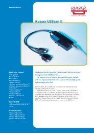
Kvaser Drivers<br />
MotoServer<br />
MotoTune<br />
MotoHawk<br />
Follow installation instructions for each one.<br />
Note: It is recommended that you do not plug the adapter cable<br />
into the USB port prior to installing the Kvaser drivers.<br />
It is also recommended that you download the CAN King<br />
software — a useful tool when working with CAN networks.<br />
Phone: 877.234.1410 support@neweagle.net www.neweagle.net<br />
Website Resources http://mcs.woodward.com<br />
MotoHawk Resource Guide: Chapter 1 Intro - Page 5
Creating an application in MATLAB<br />
Once you have completed the installation of your software,<br />
create a model to verify operation.<br />
Start MATLAB: Double click on the MATLAB icon<br />
on your desktop or select from the programs menu.<br />
The following screen will appear.<br />
At the command line<br />
type: motohawk_project (‘MyFirstProject’)<br />
Press the Enter key.<br />
the following window will open<br />
(Allow 1-2 minutes for the application to complete.)<br />
Take note of the:<br />
Target Definition<br />
Main Power Relay<br />
Trigger blocks<br />
These comprise a rudimentary system. The executable<br />
algorithms reside in the Triggered Subsystem (Foreground.)<br />
Phone: 877.234.1410 support@neweagle.net www.neweagle.net<br />
Default Application<br />
MotoHawk Resource Guide: Chapter 1 Intro - Page 6
The MATLAB window will look like this<br />
Building Your Application<br />
Press CTRL+B<br />
The MATLAB window should look like this<br />
If the message says “Successful MotoHawk Generation (No<br />
Build,)”check your Greens Hills Compiler installation: Type<br />
“motohawk_check_ghs” (a zero indicates that you have a<br />
problem with your Green Hills Compiler installation.)<br />
If you get an error, check with your instructor or e-mail the log file<br />
(MyFirstProject.log in this example) to: MCSsupport@woodward.com.<br />
A Technical Support Representative will contact you.<br />
Once you have successfully built your default application,<br />
open Windows Explorer and navigate to the C:\ECUFiles<br />
directory.<br />
You will see a number of subdirectories including Programs and<br />
TDBDLL. These subdirectories contain, respectively, the .srz<br />
and .dll files which are used by MotoTune to program the ECU.<br />
Phone: 877.234.1410 support@neweagle.net www.neweagle.net<br />
MotoHawk Resource Guide: Chapter 1 Intro - Page 7
Assembling Your Kit<br />
Install your isolated USB hub and apply power.<br />
Insert your silver MotoTune dongle into the hub.<br />
Connect the USB to CAN adapter and wait for Windows to<br />
auto-detect it. When the <strong>New</strong> Hardware window appears<br />
select “No, not this time” and click on next. Then, let Windows<br />
automatically install the drivers.<br />
Connect the Development Harness to the module<br />
(see datasheet for proper positioning.)<br />
Connect Power branch to a 12 volt source (9V to 16 V, 3A min.)<br />
Attach the SmartCraft connector, USB to CAN adapter, and<br />
the power switch to the 6 position hub.<br />
Starting MotoTune<br />
From the Start menu (or desktop shortcut) select<br />
All Programs/MotoTools/MotoTune.<br />
The following window appears<br />
The name that was used to order your kit should appear at the top of<br />
the window. If it indicates [Unlicensed,] then you need to insert/reinsert<br />
the silver dongle.<br />
Checking MotoServer<br />
Right-click on the Satellite Dish icon for MotoServer.<br />
(Located on the system tray.)<br />
Select “Ports”.<br />
If not already listed, Add location PCM-1 as a CAN type port with Access<br />
Level 4, check the box on the list, and click on “Apply”.<br />
You are now ready to connect to the module.<br />
Programming the Module<br />
Turn power on and apply ECUP signal via power switch.<br />
Select File/Program, in the MotoTune window.<br />
The following pop-up appears<br />
This is the file created when you pressed CTRL+B.<br />
Double-click on the .srz file in the window.<br />
Phone: 877.234.1410 support@neweagle.net www.neweagle.net<br />
MotoHawk Resource Guide: Chapter 1 Intro - Page 8
The Program ECU status pop up appears<br />
If the Program ECU status pop-up doesn’t advance to<br />
Connecting, check your CAN to USB and SmartCraft connections.<br />
If they are operational, turn power off. Install the BOOT KEY<br />
from your kit onto the SmartCraft hub.<br />
(ECU555-128 users will also need to move the fuse from the<br />
Normal socket to the BOOT socket to insure boot loader is invoked.)<br />
Double-click on the .srz file and apply power.<br />
If this does not work, check with your instructor or send<br />
an e-mail to: MCSsupport@woodward.com.<br />
When you see the Programming Successful message,<br />
you are ready to create a display for your application.<br />
Creating A Display<br />
In the MotoTune Window, select File/<strong>New</strong>/Online Display/<br />
Calibration.<br />
Select Display on the pop-up and click on OK.<br />
The Create <strong>New</strong> Display window appears<br />
Give your display a meaningful name (ie. MyFirstProjectDisplay.)<br />
Select “Next” for default Row and Column settings.<br />
Select “Next” for default Status Bar and Tab Control settings.<br />
Use default Sheet1 by clicking on “Finish.”<br />
The following should appear<br />
Click on the “+” next to the MyFirstProject folder<br />
(listed on left side of the MotoTune window.)<br />
Open the: >Foreground folder<br />
>Controller folder<br />
>Plant folder<br />
Double-click on the Foreground block in your<br />
Simulink model.<br />
Note the one-to-one correspondence between the MotoTune folders and the<br />
subsystems in your model.<br />
Phone: 877.234.1410 support@neweagle.net www.neweagle.net<br />
MotoHawk Resource Guide: Chapter 1 Intro - Page 9
Checking Operation<br />
Open the System folder, then the Performance folder.<br />
Drag each of the display variables onto the spreadsheet.<br />
Note that your system is running — these are its vital statistics.<br />
Cycle the power switch off, then back on.<br />
Note that the display values briefly disappear, then return.<br />
The Main Power Relay can be heard releasing and engaging.<br />
Close this model by clicking on the red “X” in the upper right<br />
hand corner.<br />
You will be prompted to save the model. We are done with this one — you<br />
may save or not.<br />
First Application<br />
Click the Simulink icon<br />
Simulink’s Library Browser appears<br />
These are the Simulink and MotoHaw blocks which, are used for creating<br />
your application models.<br />
In the MATLAB window, move up one level to the “work”<br />
directory. Create a new directory “MySecondProject” and<br />
double-click on it.<br />
In the library browser, click here<br />
A new model window opens.<br />
Note the status window in the lower left hand corner.<br />
It indicates ODE45 this stands for Ordinary Differential<br />
Equation 4th and 5th derivative (Dormand-Prince method,)<br />
which is the type of solver that will be used for simulations.<br />
Generating Embedded Code<br />
In order to generate embedded code we must<br />
change to a fixed-step discrete solver as follows:<br />
Select “Simulation” at the top of the window, then<br />
“Configuration (or Simulation) Parameters.”<br />
The following window appears<br />
Using the pull downs, change Type to Fixed-step, and Solver<br />
to Discrete (no continuous states.)<br />
Phone: 877.234.1410 support@neweagle.net www.neweagle.net<br />
Simulink Icon:<br />
located top of the MATLAB window.<br />
MotoHawk Resource Guide: Chapter 1 Intro - Page 10
Click on Apply and OK.<br />
In the library browser, click on MotoHawk. Drag the MotoHawk<br />
Target Definition block from the bottom of the list into your<br />
model. Double-click on the block and verify that the target<br />
module is correct for your kit (80 pin, 128 pin, etc).<br />
The Memory Layout should be DEV.<br />
Click on Apply and OK.<br />
From the Trigger Blocks library, drag a MotoHawk Trigger block<br />
into your model. Double-click on the block to open the dialog<br />
box and set the pull-down to FGND_RTI_PERIODIC.<br />
Click Apply and OK.<br />
From the Extra Development Blocks library, drag a<br />
Main Power Relay block into your model.<br />
(Default settings will serve our purposes for now)<br />
From the Ports & Subsystems library drag a Function-Call<br />
Subsystem block into your model. Double-click on this block<br />
and a new window appears.<br />
From the Sources library, drag the Sine Wave block<br />
from the bottom of the list into your model.<br />
Click on Sinks and drag a Scope block into your model<br />
Click on Math Operations and drag in a Gain block.<br />
Note the greater than (>) symbols on each block. These are Simulink ports,<br />
which are used to control the signal flow through your model.<br />
The Sine Wave block, being a signal source, has only one (output) port.<br />
Likewise the Scope block, being a sink, has only one (input) port, while<br />
the Gain block has one of each.<br />
More complex blocks will have more input or output ports or both.<br />
Select the Sine Wave block, hold down the CTRL key<br />
and click on the Gain block<br />
Notice how Simulink connects the two blocks. This technique can be used<br />
to “wire” the blocks to one another and is especially useful when wiring<br />
signals to or from consecutive ports on a block. Simulink will start at the<br />
top and work down either side (in or out) of the block.<br />
At the top level of your model, connect the trigger block to<br />
the subsystem block. Select File/Save As. Give your model a<br />
meaningful name (ie. MySecondProject) and click Save.<br />
Phone: 877.234.1410 support@neweagle.net www.neweagle.net<br />
MotoHawk Resource Guide: Chapter 1 Intro - Page 11
Press CTRL + D.<br />
Notice that Simulink has generated an error message and highlighted the<br />
offending subsystem and block — informing us that “only constant or<br />
inherited (-1) sample times are allowed in triggered subsystems.”<br />
Double-click on the Sine Wave block to open its dialog box.<br />
At the bottom of the dialog box the Sample Time is zero.<br />
As you may have guessed this means continuous.<br />
Change it to -1 (inherited.)<br />
The subsystem will now inherit its sample time from the parent (level above,)<br />
which is FGND_RTI_PERIODIC or 5 milliseconds.<br />
Press CTRL + D again.<br />
No error messages are generated.<br />
Double-click on the scope — a pop-up window appears<br />
complete with grid and axis markings.<br />
Select Simulation/Start — a Sine wave appears.<br />
Double-click on the Gain block, change to 100.<br />
The small triangle in the middle of the window at the top can be used to start<br />
the simulation. Note that the Sine wave has changed.<br />
Click on the binoculars icon<br />
This will scale the display for your input automatically. Clicking on the name<br />
of the subsystem (Function-Call Subsystem) opens it for editing.<br />
Change the name to “Foreground.”<br />
Press CTRL + B<br />
MotoHawk builds your application.<br />
In the MotoTune Display Explorer pane, right-click on Display1<br />
on [PCM-1.] Select “Save As” and give it a meaningful name<br />
(ie. ”MyFirstProjectDisplays”). Use pulldown to specify the folder.<br />
Note that while MyFirstProjectDisplays contains only MyFirstProjectDisplay,<br />
it may contain others that provide different views into the system.<br />
Right-click on MyFirstProjectDisplays and select Close.<br />
Currently, this is the only way to close one display and open another in MotoTune.<br />
Select File/Program and download MySecondProject into<br />
the module. Create a new display as above.<br />
(ie. “MySecondProjectDisplay.”)<br />
Drag in your System Performance variables and note, via your<br />
display and the Main Power Relay, that your application is running.<br />
Phone: 877.234.1410 support@neweagle.net www.neweagle.net<br />
MotoHawk Resource Guide: Chapter 1 Intro - Page 12
Modifying the application<br />
Allows you to gain some control over its operation.<br />
Double-click on the Foreground block in your model, select the<br />
Sine wave generator and the gain block, press the delete key<br />
to remove these blocks.<br />
From the Calibration & Probing Blocks library, drag a<br />
motohawk_calibration block and a motohawk_probe block<br />
into your model.<br />
From the Extra Development Blocks library, drag in a<br />
motohawk_abs_time block.<br />
Double-click on the Calibration block and change the name to<br />
‘TwoPi’ and value to 6.28318.<br />
The single quotes must be used.<br />
From the Math Operations library, drag in a Product block.<br />
Double-click on it and change the number of inputs to 3.<br />
Right-click on the TwoPi block and drag down.<br />
A duplicate block is added to your model.<br />
Double-click on the new block and change its name to “f”<br />
and its value to 1.<br />
Wire these 3 blocks to the inputs on the Product block.<br />
From the Math Operations library, drag in a Trigonometric<br />
Function block.<br />
If it is not already set to Sine, change it.<br />
Wire the output of the Product block to the input of the<br />
Trigonometric Function block.<br />
Wire the output of the Trigonometric Function<br />
block to the Scope block.<br />
Double-click on the Probe block and change its name to Sine.<br />
Place the cursor over the input port of the “Sine” Probe block.<br />
Notice that the cursor changes into a cross-hairs.<br />
Click on the port and drag to the wire connecting the<br />
Trigonometric Function block and the Scope.<br />
A connection dot appears on the wire and a wire connects to<br />
the Sine Probe block.<br />
Phone: 877.234.1410 support@neweagle.net www.neweagle.net<br />
MotoHawk Resource Guide: Chapter 1 Intro - Page 13
Your model should look similar to this<br />
Press CTRL + D (see that there are no errors.)<br />
Press CTRL + B (verify that the build is successful.)<br />
Close the display in the MotoTune Display Explorer pane as<br />
above and program the module with your modified application.<br />
Select File/<strong>New</strong> and create a new calibration.<br />
In the Calibration Explorer pane, Click on the “+” next to the<br />
MySecondProject folder.<br />
Double-click on Foreground.<br />
A Calibration sheet opens in the right hand pane of the<br />
MotoTune window.<br />
Create another display sheet and drag it down or to the side<br />
such that both are visible.<br />
You should be able to see the Sine value changing.<br />
Right-click on the cell containing the Sine value and select<br />
Properties. Click on Set Fast and verify that the Add to chart/<br />
log box is checked. Click OK.<br />
Select Chart/Open Chart.<br />
A pop up appears displaying your Sine wave.<br />
In the Foreground sheet change the “f” value to 2.<br />
Note the frequency changes when the Enter key is pressed.<br />
Change “f” to 0.5 – observe change in chart.<br />
Occasionally, flat spots will appear on the chart – a result of Windows OS<br />
“garbage collection” and other operations, and is no cause for concern.<br />
Introducing a Gain Stage<br />
Select the wire connecting the Trigonometric Function block<br />
and the Scope and press the Delete key.<br />
Right-click on the TwoPi block and drag a copy to one side.<br />
Double-click on the new block and change the name to<br />
‘Amplitude’ and the value to 10.<br />
Likewise, copy over the product block and change its Number<br />
of inputs to 2.<br />
Phone: 877.234.1410 support@neweagle.net www.neweagle.net<br />
Two methods for introducing a gain stage<br />
Method 1 — add a Gain block from the Math Operations library.<br />
Method 2 — add a Product block from the same library and a Calibration block from the<br />
MotoHawk library.<br />
In the case of a Gain block; Real Time Workshop will allow us to change the Gain value<br />
during simulation but our objective is to generate embedded code.<br />
The RTW Embedded Coder treats a Gain block as a hard-coded constant which, precludes<br />
changes at run-time. Therefore, we will use the second approach; an “Amplitude”<br />
calibration block and a product block.<br />
MotoHawk Resource Guide: Chapter 1 Intro - Page 14
Connect the new calibration block and the Sine block to the<br />
product block inputs.<br />
Wire the product block output to the Scope and Sine probe block.<br />
Your model should look similar to this<br />
Press CTRL + D and verify that there are no errors.<br />
Then press CTRL + B to build it.<br />
Program the module with the new application. Set up your display<br />
and calibration windows in MotoTune as before.<br />
Open a chart for the Sine probe and verify the amplitude value.<br />
Now change the amplitude to 100.<br />
Note that the display is rescaled for the new value.<br />
If a Cosine signal of the same amplitude is also needed:<br />
Hold down the Shift key and select the Amplitude,<br />
Trigonometric Function, Product, and Sine Probe blocks from<br />
the Right side of the drawing.<br />
Right-click and drag down to copy them.<br />
Wire the blocks together as before, connecting the input of the<br />
Trigonometric Function to the output of the Product block on<br />
the Left.<br />
Change the Trigonometric Function to Cosine and rename the<br />
Probe block accordingly.<br />
Your model should look similar to this<br />
Press CTRL + D.<br />
Read the error message. Simulink is complaining that the name ‘Amplitude’<br />
is not unique. We could rename this, but we know that the value is important<br />
and it would be convenient to be able to re-use it. The way to do this is to use<br />
the MotoHawk Data Storage blocks.<br />
MotoHawk Data Storage Blocks<br />
From the library, drag a motohawk_data_def block and<br />
a motohawk_data_read block into your model.<br />
Double-click on the motohawk_data_def block, change the<br />
name to ‘Amplitude’, change the Storage Class to constant,<br />
and verify that “Attach a VarDec for Visibility from MotoTune”<br />
is checked.<br />
Phone: 877.234.1410 support@neweagle.net www.neweagle.net<br />
MotoHawk Resource Guide: Chapter 1 Intro - Page 15
Highlight the two calibration blocks called “Amplitude” and<br />
delete them.<br />
Double-click on the motohawk_data_read block, change the<br />
name to ‘Amplitude’, and drag it over to one of the loose wires<br />
left by the previous deletion.<br />
Right-click on the motohawk_data_read block and drag a copy<br />
over to the other loose wire.<br />
Press CTRL + D again.<br />
No errors should be generated.<br />
Build your model, program the module, and set up your<br />
display and calibration windows as before.<br />
(using the MotoHawk Data Storage blocks continued)<br />
Right-click on either the Sine or the Cosine value and set the<br />
properties to:<br />
>Fast<br />
>Add to chart/log<br />
>Apply to all<br />
Click OK.<br />
Select Chart, Open Chart and observe your signals.<br />
In the calibration pane change the Amplitude value and<br />
observe the changes in your signals.<br />
For calibration values that are used in only one place in the model, the<br />
motohawk_calibration block is a convenient means of introducing the<br />
variable.<br />
When a calibration is to be used in more than one place, a motohawk_data_<br />
def block with motohawk_data_read blocks is best.<br />
Read More<br />
MotoTune Options<br />
Selecting Attach VarDec for Visibility from MotoTune expands<br />
the dialog box giving us more options.<br />
Phone: 877.234.1410 support@neweagle.net www.neweagle.net<br />
Data Storage Blocks: A closer look<br />
Double-click on the motohawk_data_def block.<br />
A brief description of the block’s parameters appears at the top of the dialog box. In addition<br />
to the variable’s name, initial value, and storage class, we can specify a data type (click on the<br />
pull down to see them), and an Output Reference Data type (for pointer based operations.)<br />
The Storage Class Parameter...<br />
allows us to specify the type of resource that will be allocated for the variable.<br />
Constant, as the name implies...<br />
does not change unless a tool changes it.<br />
Volatile...<br />
will be re-initialized at power up.<br />
Non-volatile...<br />
will be preserved across a controlled shut-down/power-up cycle (when MPRD block or similar<br />
construct is included in the model).<br />
Attach VarDec for Visibility offers:<br />
a choice of which pane to view it in: Calibration or Display.<br />
the option to restrict Read and Write access level.<br />
whether to use uploaded calibration values from MotoTune.<br />
how to view the value: Number, Enumeration (on, off, running, stopped,) or Text.<br />
Select the Help button at the bottom of the dialog box to view remaining options.<br />
If the MPRD block is not used, a motohawk_store_nvmem must be included in a background<br />
subsystem in order to execute the transfer to EEPROM (with the caveat that there are a limited<br />
number of write cycles for the EEPROM devices.)<br />
Also, when a revised model is downloaded to the module, the values stored in EEPROM will be<br />
loaded into RAM unless the structure has changed or the RestoreNVFactoryDefaults function is<br />
invoked from the System\NonVolatile Storage folder in the Display pane.<br />
Example: You are adjusting calibration values and you decide to change the logic in<br />
your module (ie. change a greater-than to a greater-than-or-equal-to.) You can rebuild the<br />
application, reprogram the module, and pick up where you left off, without having to up-load<br />
the calibration.<br />
MotoHawk Resource Guide: Chapter 1 Intro - Page 16
Calibration and Probing Blocks<br />
Another useful block is the motohawk_override_abs block<br />
from the Calibration and Probing library.<br />
Drag one into your model and place it over the wire connecting<br />
the first product block to the trigonometric function blocks.<br />
Note: Simulink breaks the wire, making the necessary connections.<br />
Double-click on the block and give it a meaningful name<br />
(ie. “Angle_Override”.)<br />
Click on Apply and OK.<br />
Press CTRL + D and CTRL + B.<br />
Program the module and set up your Display and Calibration<br />
panes as before.<br />
Your model should look similar to this<br />
Drag the two new parameters from the Foreground\Angle_<br />
Override folder into the Display spreadsheet.<br />
Start a chart for your Sine and Cosine waves.<br />
Set Angle_Override_new to 3.14.<br />
Click on the value for Angle_Override_ovr.<br />
A pull-down arrow appears next to the cell.<br />
Click on the pulldown and select override.<br />
Look at your chart to see the effect of this change after<br />
pressing Enter. As expected, the Sine value goes to 0 while the<br />
Cosine value goes to -1.<br />
The override is a display, not a calibration.<br />
Read more<br />
Gathering data<br />
We have seen how a data definition block is used to introduce<br />
a constant into the system. Now, look at how it can be used to<br />
gather data from our system.<br />
From the Ports & Subsystems library, drag in an enabled<br />
subsystem and delete the scopes. Double-click on the<br />
Phone: 877.234.1410 support@neweagle.net www.neweagle.net<br />
Display or Calibration... What’s the difference?<br />
Displays allow the Engineer or Technician to monitor or manipulate signals in the system to<br />
establish conditions necessary for testing or calibration.<br />
The changes made via Display variables are not saved in the .dis file and so do not persist<br />
past the MotoTune session.<br />
On the other hand, Calibration changes are saved in a .cal file and can be Merged with or<br />
Transfer Upgraded into another calibration (or .srz) file to create a new .cal (or .srz) file<br />
which contains the desired changes.<br />
MotoHawk Resource Guide: Chapter 1 Intro - Page 17
enabled subsystem and a new window opens up.<br />
Delete the output port and copy the input port by right-clicking<br />
on port 1.<br />
From the commonly used blocks library, drag in a constant<br />
block and a sum block.<br />
From the math operations library, drag in a math function block.<br />
From the discrete library drag, in a unit delay block.<br />
Right click to copy the constant block. Set the value of the new<br />
(constant1) block to 200.<br />
Double-click on the math function block and use the pull-down<br />
to select mod (modulo) function. Click on Apply and OK.<br />
Right click on the mod block and select format and flip block.<br />
Likewise flip the unit delay and constant1 blocks.<br />
Wire the constant and mod blocks to the sum block inputs.<br />
Wire the output of the sum block to the input of the unit delay<br />
block and the outputs of the unit delay and constant1 blocks<br />
to the inputs of the mod block.<br />
From the data storage blocks library, drag in a motohawk_<br />
data_write block and make a copy of it.<br />
Double-click on the first data write blocks. Name it SineData.<br />
Using the pull down, set data structure to vector.*<br />
Name the second data write block CosineData and make it a<br />
vector* as well.<br />
* When you set up the Data Write Blocks as Vector, select ‘Write Scalar into<br />
element by index”.<br />
Wire the idx input of each data write block to the output of the<br />
sum block.<br />
Wire input1 to the data input of the SineData block and input2<br />
to the CosineData block.<br />
Your enabled subsystem should look like this<br />
Save file and close this window.<br />
In the Foreground window, right-click on the<br />
Phone: 877.234.1410 support@neweagle.net www.neweagle.net<br />
MotoHawk Resource Guide: Chapter 1 Intro - Page 18
Amplitude data definition block and make two copies.<br />
Double-click on the first copy, change the name to SineData,<br />
change the Storage Class to NonVolatile, and change MotoTune<br />
Window to Display.<br />
Place the following in the Initial Value box: zeros (1,200.)<br />
Click Apply and OK.<br />
Double-click on the second copy, change the name to<br />
CosineData, Storage Class to NonVolatile, and MotoTune<br />
Window to Calibration.<br />
Click Apply and OK.<br />
Place the following in the Initial Value box: ones (1,200.)<br />
Copy the ‘f’ calibration block and rename it.<br />
Log and set the initial value to zero.<br />
Wire the Sine signal to In1 and the Cosine signal to In2 of the<br />
enabled subsystem.<br />
Wire the Log block to the input at the top of the enabled<br />
subsystem.<br />
Your model should look like this<br />
Press CTRL - D. If there are no errors, press CTRL - B.<br />
Start MotoTune and create a new display and a new calibration.<br />
In the display pane expand MySecondProject and Foreground.<br />
Drag SineData into the worksheet.<br />
Note that all of the values have been set to zero.<br />
In the calibration pane, expand MySecondProject.<br />
Note the folder and sheet of paper, both named Foreground.<br />
Expand each to see their contents.<br />
The folder contains the CosineData vector array (another sheet of paper). The<br />
sheet of paper contains the scalar variables. Both have been defined in the<br />
Foreground layer of the model and the default group string was used.<br />
Confusing? Read more<br />
Phone: 877.234.1410 support@neweagle.net www.neweagle.net<br />
Two ways to get around the confusion:<br />
The first would be to utilize the Show MotoTune Group check box and explicitly name the<br />
MotoTune Group String.<br />
The other would be to place the data definition blocks in the enabled subsystem.<br />
The system designer needs to decide what is the best way to organize these data<br />
structures, a CTRL - B is required to generate a new DLL.<br />
MotoHawk Resource Guide: Chapter 1 Intro - Page 19
For now, double-click on the Foreground and the CosineData<br />
sheets of paper and arrange them in the window.<br />
Copy the “f” box and label it “Log”; set the value to 0.<br />
Put the following in the initial value box of SineData:<br />
“zeros (1, 200). That is one, comma, 200, not twelve thousand.<br />
Do the same for CosineData.<br />
Your window should look like this<br />
Note that the CosineData array contains all 1s.<br />
Changing the Log variable to 1 enables the subsystem that<br />
logs the data.<br />
The SineData array changes immediately, but the CosineData does not.<br />
Select Calibration-Refresh Volatile Map (or press F5) and the<br />
CosineData array is updated.<br />
The Sine Data array may be used to examine the Sine values and can be<br />
copied and pasted into a spreadsheet for analysis.<br />
If there is no need to edit the values offline (factory defaults<br />
are a good starting point for an adaptive algorithm,) the<br />
Display variable will suffice.<br />
If, however, the values are best customized based on which<br />
variety of installations it will be used on, then the Calibration<br />
variable is the one to use.<br />
We are done with this example — you may close it.<br />
Phone: 877.234.1410 support@neweagle.net www.neweagle.net<br />
MotoHawk Resource Guide: Chapter 1 Intro - Page 20
Throttle Control Challenge<br />
The following example uses a slider potentiometer and an<br />
electronically controlled throttle assembly:<br />
Table 1 lists the signals and their corresponding connector pin<br />
numbers.<br />
The Slider pot should be connected to XDRP, XDRG, and<br />
AN1M.<br />
POT1 and POT2 should be connected to AN2M and AN3M<br />
respectively.<br />
Consult the datasheet for your module to determine the appropriate wire<br />
number for each of the signals.<br />
At the Simulink command line, use the motohawk_project<br />
instruction to open a new project. Name it ThrottleControl.<br />
Double-click on the Foreground block and delete the Controller<br />
and Plant blocks.<br />
From the MotoHawk Analog I/O Blocks library, drag in a<br />
motohawk_ain block.<br />
Select “Allow I/O pin to be calibrated from MotoTune,” and<br />
name the block ThrottlePedal.<br />
Select AN1M from the pull down and click on “Apply” then<br />
“OK.”<br />
Drag in a Gain block and a motohawk_probe block.<br />
Wire the ThrottlePedal block to the Gain block and the Gain<br />
block to the motohawk_probe block.<br />
Set the Gain block Gain to 100/1023.<br />
Name your probe SetPoint.<br />
Press CTRL - D.<br />
Phone: 877.234.1410 support@neweagle.net www.neweagle.net<br />
Pin Number Signal Name<br />
1 Motor-<br />
2 XDRG<br />
3 XDRP<br />
4 Motor+<br />
5 POT2<br />
6 POT1<br />
Table 1: Electronic Throttle Connector Pinout<br />
Electronic Throttle/Slider Potentiometer Schematic<br />
MotoHawk Resource Guide: Chapter 1 Intro - Page 21
In MATLAB 7.0, the following error message appears<br />
MATLAB 7.0 supports a fixed point data type called ufix16_eng19 which<br />
requires a separate license. Other versions of MATLAB will issue a data type<br />
mis-match error. This is because MATLAB uses a default data type of double,<br />
while the data type for a particular resource is dependant on the hardware.<br />
In this instance, the A/D on the 555 is 10 bits, which fits into a unit16.<br />
Other resources have the following data types:<br />
Digital Inputs and Outputs are Boolean<br />
Frequency Inputs and Outputs are uint32 (scaled by 0.01Hz)<br />
Duty Cycle Inputs and Outputs are int16.<br />
Go to the top level of your model, double-click on the Target<br />
Definition block and click on the “Floating Point Data Type”<br />
pull down.<br />
The choices are: single (32 bits)<br />
double (64 bits)<br />
disabled<br />
These determine the way that memory will be allocated during code<br />
generation. The default is single (32 bits) and should not be changed<br />
unless greater resolution is required or the target processor does not<br />
support floating point operations.<br />
Return to the Foreground level of your model and drag a Data<br />
Type Conversion block in from the Signal Attributes library.<br />
Place it between the ThrottlePedal block and the Gain block.<br />
Press CTRL - D again.<br />
There should be no errors reported.<br />
From the Format menu select Port/Signal Displays and check<br />
Port Data Types.<br />
The data type appears adjacent to each wire. This is a convenient way to<br />
verify that your data types are consistent in your model.<br />
Make copies of the analog input, data type conversion, gain,<br />
and probe blocks.<br />
Highlight them and select Format-Flip Block (or CTRL - I ).<br />
Select AN2M for the analog input, name the probe Feedback.<br />
Drag in a motohawk_pwm block from the Analog I/O Blocks<br />
library and select H1 as the resource.<br />
Phone: 877.234.1410 support@neweagle.net www.neweagle.net<br />
MotoHawk Resource Guide: Chapter 1 Intro - Page 22
Drag in a motohawk_calibration block. Name it ETC_<br />
Frequency and set the Default Value to 5000.<br />
To make a proportional control like the one shown, double-click<br />
on the summing node and change the list of signs to |+|- .<br />
Copy and modify the gain block and data conversion blocks.<br />
When you first wire in your blocks, the data type adjacent to each wire will<br />
indicate double (MATLAB’s default), but when you press CTRL - D they are<br />
updated to indicate the appropriate data type.<br />
Press CTRL - B to build your model and use MotoTune to<br />
download it to the module.<br />
Operate the Throttle Pedal slider and observe the behavior.<br />
This model is a simple proportional control. Realistically, a<br />
more complex control is required.<br />
Fault Detection on Throttle Pedal<br />
The next model introduces rudimentary fault detection on the<br />
Throttle Pedal Position sensor and adds an integrating term to<br />
the command signal. It also includes diagnostic probes and<br />
calibratable Proportional and Integral gains.<br />
Modify your drawing to look like the one shown.<br />
Press CTRL - D to check your model.<br />
Then build it using CTRL-B.<br />
Open a display and a calibration in MotoTune. Set up your<br />
probes and adjust the ETC_Frequency value until the high<br />
pitched sound can no longer be heard.<br />
Set the Integral Gain to zero and increase the proportional gain<br />
until the throttle plate exhibits ringing when operated.<br />
Open a chart and increase the Integral Gain until the traces for<br />
SetPoint and Feedback come together.<br />
The Error trace should be zero.<br />
Phone: 877.234.1410 support@neweagle.net www.neweagle.net<br />
This value represents the difference, or<br />
error, between the Throttle Pedal Value<br />
and the actual Throttle Pedal Position.<br />
MotoHawk Resource Guide: Chapter 1 Intro - Page 23
CHAPTER 2 : Faults<br />
About Faults 1<br />
MotoHawk Fault Theory of Operation 2<br />
Fault Blocks 3<br />
Fault Manager 3<br />
Fault Definition 4<br />
Set Fault & Clear Fault 4<br />
Fault Status 5<br />
Clear All Faults 5<br />
Fault Action 6<br />
Example 7-8<br />
Phone: 877.234.1410 support@neweagle.net www.neweagle.net<br />
FAULTS<br />
This section covers the basics of faults within MotoHawk.<br />
About Faults<br />
system failure<br />
system failure<br />
system failure<br />
system failure<br />
Faults are used to indicate failures within a system.<br />
For instance, if a sensor becomes disconnected, the application can detect this out of range<br />
condition and signal the issue via a fault.<br />
Fault diagnosis usually accounts for 50-70% of the code within any production application.<br />
In other words, when you have the control logic done but not the fault detection, you are only<br />
about 1/3 to 1/2 done with your application. MotoHawk provides a nice set of blocks to help you<br />
signal faults and take actions as a result of faults.<br />
Faults are nothing more than signals that some logic has found an issue within the system.<br />
Fault diagnosis and identification is a complex subject that changes based on the application.<br />
However, you will find that all good applications at least diagnose sensor failure, and should diagnose<br />
actuator failures if possible. Why? Because wiring harnesses fail, sensors fail, and actuators fail.<br />
Ideally, your application will do three things well:<br />
Fault Containment — the act of keeping a fault from propagating to other parts of the system.<br />
Fault Identification — the act of determining, as precisely as possible, the source of the fault.<br />
Fault Annunciation — the act of reporting the fault to someone who can fix it.<br />
Fault Action — the act of adjusting system operation in response to the fault.<br />
Some faults are easy to detect — like a signal being out of range. Others can be terribly difficult<br />
— like a signal stuck in range. Unfortunately, MotoHawk does not help you with the containment or<br />
identification problems. That is the job of the application designer. MotoHawk will however, allow you<br />
to record the faults, help annunciate them and help interface to action code.<br />
MotoHawk Resource Guide: Chapter 2 Faults - Page 1
MotoHawk Fault Theory of Operation<br />
MotoHawk contains a series of blocks that allow you to signal<br />
a fault, read the fault status, change the fault status, and take<br />
fault actions.<br />
The easiest way to think about this — you have fault signals<br />
and fault actions...<br />
Fault signals are an indication that a fault has occurred.<br />
Fault Actions are what the application should do when<br />
various faults occur.<br />
Phone: 877.234.1410 support@neweagle.net www.neweagle.net<br />
MotoHawk allows you to route multiple faults to a single fault action. This is a powerful idiom that<br />
will simplify the designer’s job. Because fault actions are independent of faults, there is no need to define<br />
various levels of seriousness to the faults. The seriousness is contained within the application.<br />
For instance, an engine designer may design a fault that detects low oil pressure and an action that<br />
is capable of shutting down the engine. He can then decide if low oil pressure is worthy of shutting<br />
down the engine. Often times, this decision cannot be made at design time.<br />
You may be building an engine that can be installed in a trash truck and a fire truck. Shutting down<br />
a trash truck because of low oil pressure is probably very desirable so that the engine can be<br />
repaired. However, most fire departments would just as soon pump water onto the fire until the<br />
engine is reduced to a pile of molten metal rather than shut the engine down.<br />
MotoHawk respects this and allows you to calibrate faults to fault actions, rather than requiring the routing<br />
be set at design time. This allows a single code build to handle both of the example cases with just a<br />
change in the calibration.<br />
Faults also need to have filtering. MotoHawk faults provide an X out of Y test which, basically says that<br />
the fault must be present X times out of Y samples to be declared active.<br />
Faults are considered “Suspected” whenever any of the Y number of samples have<br />
detected the fault but the number is less than X.<br />
Faults are “Active” when at least X out of Y have occurred.<br />
In addition to filtering, MotoHawk faults have some different behaviors. A Fault can be:<br />
Disabled — meaning it will not signal a fault even if the X out of Y condition is satisfied.<br />
Sticky — meaning that once set it will remain set until the next power down or until it is<br />
explicitly cleared. This setting is handy for detecting transient or intermittent faults that<br />
may appear and disappear before they can be observed in MotoTune.<br />
Persistent — a fault that acts like the “Sticky” fault, in that it will remain set once the<br />
fault conditions occur. But it will remain set across a power cycle. A persistent fault<br />
once set will remain set until it is explicitly cleared.<br />
Fault Actions can be initiated by one or more faults. Any given fault can drive up to four fault actions based<br />
on various states of the fault (i.e. Suspected or Active). The fault action block will report a high Boolean<br />
signal when any of the associated faults are set. The application designer is then responsible to define the<br />
proper system response.<br />
MotoHawk Resource Guide: Chapter 2 Faults - Page 2
Fault Blocks<br />
MotoHawk provides several blocks to define and interact<br />
with faults within your system.<br />
These are located in the MotoHawk Library under Fault<br />
Management.<br />
Fault Manager<br />
This block can exist anywhere in your model. You will need<br />
only one for the model. The storage for the fault manager<br />
allows you to control where the fault calibration is stored.<br />
If set to FLASH — the faults can only be calibrated on a<br />
development module or offline.<br />
If set to EEPROM — the calibration can be adjusted on any<br />
module.<br />
The access level refers to the security level required of the<br />
MotoTune user to perform the action.<br />
The MotoTune group string controls where the Fault calibration<br />
will be shown in the MotoTune Calibration Tree.<br />
Phone: 877.234.1410 support@neweagle.net www.neweagle.net<br />
MotoHawk Resource Guide: Chapter 2 Faults - Page 3
Fault Definition<br />
This block defines a fault in your system. Faults must have<br />
unique names throughout the system.<br />
Set Fault & Clear Fault<br />
These blocks will set or clear a fault that has been defined<br />
elsewhere.<br />
The application is responsible for coordinating when these blocks run<br />
— there is no coordination done by the Fault Manager.<br />
Phone: 877.234.1410 support@neweagle.net www.neweagle.net<br />
MotoHawk Resource Guide: Chapter 2 Faults - Page 4
Fault Status<br />
These blocks allow you to read the status of a single fault or<br />
a group of faults.<br />
When reading multiple statuses, the output will be a vector<br />
of boolean values corresponding to the fault list.<br />
Clear All Faults<br />
This block, when triggered will clear all of the faults.<br />
If the fault conditions still exist, once the X of Y filters are<br />
satisfied, the faults will re-activate.<br />
Phone: 877.234.1410 support@neweagle.net www.neweagle.net<br />
Motohawk_get_faults(system:)<br />
This is a utility function that will<br />
retrieve all of the faults located in<br />
the system and its children. Use<br />
bdroot to find all faults within the<br />
model. The fault list returned by<br />
this function will be alphabetized.<br />
MotoHawk Resource Guide: Chapter 2 Faults - Page 5
Fault Action<br />
This block defines a fault action.<br />
The fault action name must be unique within a model.<br />
The action will become active when a fault is routed to it<br />
either via the design or via calibration. The application<br />
designer then needs to create the code that will execute<br />
when the fault action is active.<br />
Phone: 877.234.1410 support@neweagle.net www.neweagle.net<br />
MotoHawk Resource Guide: Chapter 2 Faults - Page 6
Example<br />
This example will demonstrate<br />
the Fault Blocks.<br />
Start with motohawk_<br />
project(‘Fault1.’)<br />
Remove the existing contents<br />
of the Foreground subsystem<br />
Create the model as shown.<br />
Build the model.<br />
Run MotoTune, program the<br />
module, and open a display or<br />
open the FaultExample.dis file.<br />
Phone: 877.234.1410 support@neweagle.net www.neweagle.net<br />
*For a larger view of drawing, open MotoHawk_Resource_Guide_11x17_drawings.pdf on the included training cd.<br />
MotoHawk Resource Guide: Chapter 2 Faults - Page 7
(example continued)<br />
Notice in MotoTune display explorer,<br />
there is a category for Faults that<br />
contains the display variables for:<br />
Active Faults<br />
Occurred Faults<br />
Suspected Faults<br />
command that will clear faults<br />
Also, for every Action there is a reason<br />
display variable that will tell you all of<br />
the faults that are causing the particular<br />
action.<br />
All of the displays are marquee type<br />
displays, that will roll through the faults<br />
and display the fault names.<br />
Open a calibration and notice the Faults<br />
category in the Calibration Explorer. The<br />
Fault Manager is located here.<br />
Open it up.<br />
The fault manager contains fields<br />
that can be set in the Simulink Fault<br />
Definition Block. They are found here<br />
and can be adjusted at run time.<br />
There is also an extra field, “Test,” that<br />
will allow you to force the fault active<br />
without the input conditions being set.<br />
Note how the calibration has been<br />
adjusted to route some of the faults to<br />
particular actions.<br />
Phone: 877.234.1410 support@neweagle.net www.neweagle.net<br />
*For a larger view of drawing, open MotoHawk_Resource_Guide_11x17_drawings.pdf on the included training cd.<br />
MotoHawk Resource Guide: Chapter 2 Faults - Page 8
CHAPTER 3 : CAN<br />
About CAN 1<br />
Introduction 2<br />
CAN Bus Basics 2<br />
Payloads 3<br />
Protocols 3<br />
What should a protocol specify? 4<br />
Examples of Protocols 4<br />
MotoHawk CAN Theory of Operation 4<br />
Using CANKing to Observe the Bus 6<br />
Basic CAN Blocks 8<br />
CAN Channel Definition 8<br />
CAN Transmit Raw 9<br />
CAN Receive Raw 9<br />
Slot Properties 10<br />
Slot Receive Trigger 10<br />
Example 11<br />
Advanced CAN Blocks 13<br />
Payload Bit Numbering 13<br />
Standard ID Bit Numbering 13<br />
Extended ID Bit Numbering 13<br />
Message Definition Structure 14<br />
Advanced Example 16<br />
Recommended Usage of CAN Message Receive Blocks 18<br />
Phone: 877.234.1410 support@neweagle.net www.neweagle.net<br />
About CAN<br />
Sending and<br />
receiving messages<br />
via a CAN port is incredibly<br />
simple. It is far easier to send or<br />
receive a message via CAN than it is a<br />
RS232. However, there are a couple of issues<br />
that can make it seem daunting — especially when<br />
talking about CAN protocols like J1939 or SmartCraft.<br />
WARNING<br />
TO THE READER:<br />
CAN IS NOT DIFFICULT!<br />
The CAN standard was invented by Bosch in the early 1990’s to facilitate the communication<br />
of data between devices in a vehicle. CAN literally means Controller Area Network.<br />
All MotoTron Control Solutions modules are compatible with the current standard — CAN 2.0B.<br />
Most of our modules have at least one CAN port, while a few have as<br />
many as three.<br />
All of our drive-by-wire marine applications require two busses for reliability and redundancy,<br />
so many modules are equipped with a pair of busses.<br />
On to the basics of what makes a CAN bus.<br />
MotoHawk Resource Guide: Chapter 3 CAN - Page 1
Introduction<br />
This section covers the basics of the CAN databus and how to use<br />
the MotoHawk facilities to interface your module to a CAN bus.<br />
CAN Bus Basics<br />
Phone: 877.234.1410 support@neweagle.net www.neweagle.net<br />
First, a CAN bus requires at least two participants in order to be a bus. The physical connection<br />
between devices is a 2 wire cable. The wires are often labeled CAN-H and CAN-L. There must be a 120<br />
ohm resistor between CAN-H and CAN-L somewhere on the bus called a terminator. The terminator resistor<br />
can be placed physically anywhere in the bus, but ideally is located at one end or the other. You can have<br />
more than one terminator, but remember that too many cause the bus to stop working.<br />
CAN bits are transmitted across the bus as either dominant or recessive. This means that a<br />
dominant bit (a 0) will win over a recessive bit (a 1). All of the transceivers on the bus must be operating<br />
at the same bit rate (aka the baud rate.) All of the transceivers on the bus synchronize to one another by<br />
detecting the edges between 1s and 0s. Luckily, the transceivers do much of the hard work of transmitting<br />
and receiving messages. The software needs only load messages to be sent and react to incoming<br />
messages. The transceivers make sure that a message gets out on the bus if possible. Commonly, busses<br />
are operated at 250K baud but can run as fast as 1M baud. The length of the bus is directly related to how<br />
fast you can run the bus. For reliable communications, the maximum range at 250K baud is 100 feet; at<br />
1M baud it is 30 feet.<br />
All CAN messages are comprised of:<br />
- An ID of either 11 bits (aka a standard ID) or 29 bits (aka an extended ID),<br />
- A Data Length Field saying how many payload bytes there are. This number can be from 0 to 8, and -<br />
A payload of 0 to 8 bytes. Notice that the payload can change sizes. Yes, a perfectly valid message can<br />
contain no payload at all. You might ask, why you would ever transmit a message with no data? Usually to<br />
indicate that a module is alive by sending a heartbeat to other modules in the system or to represent the<br />
occurrence of an event. Notice as well that IDs can be of two different types. Is it permissible to have both<br />
types on the bus at the same time? Absolutely. The bus will perform just fine with both types of IDs and<br />
variable length payloads running across it. Also, messages with IDs of the same value but different type are<br />
considered totally different messages.<br />
So, how are the inevitable bus collisions (times when two modules want to transmit at the same<br />
time) handled in CAN? Very nicely.<br />
Remember that all transceivers are synchronized. The two transmitting modules will start clocking out<br />
their ID bits at the same time starting with the most significant bit. As soon as the ID bits differ, the device<br />
that is transmitting the 0 wins the bus (because 0s are dominant) and continues clocking its bits out. The<br />
device with the 1 in the ID bit, automatically detects that it lost the bus and stops trying to transmit, and it<br />
will automatically wait until the next transmission slot to try again.<br />
So, this brings us to a couple of rules:<br />
Lower ID values have higher priority on the bus<br />
(and standard IDs are higher priority than extended IDs)<br />
No two devices can transmit the same ID.<br />
The first rule is fairly obvious. 0s are dominant, so lower IDs will make it on the bus first. The fact that<br />
standard IDs are higher priority than extended is caused by the transmitting of a 1-in-1 of the early<br />
messaged header bits to indicate that the following ID is extended.<br />
MotoHawk Resource Guide: Chapter 3 CAN - Page 2
Payloads<br />
Protocols<br />
Phone: 877.234.1410 support@neweagle.net www.neweagle.net<br />
The second rule is not as obvious, but will bite you. If two modules tried to send the same ID at the same<br />
time, neither would know that it did not win the bus. The failure would not occur until they had a different<br />
bit in the payload. Unfortunately, each module will only be informed that its message failed a parity test<br />
(due to the payload bits being clobbered). Each module will then dutifully retry to transmit. Since they are<br />
synchronized, they will once again clobber each other. So, never, ever have two modules potentially sending<br />
the same ID. Of course, never is a strong word. And, you will see that some protocols actually will break<br />
this rule to do address claiming — but more on that later.<br />
Recall that payloads can have between 0 and 8 bytes of data.<br />
Those 8 bytes can mean anything you want them to mean. The CAN 2.0B specification does not have an<br />
opinion about the contents of the payload. Of course, choosing IDs and defining payload contents can be a<br />
daunting task. If you own the entire bus design, you can simply choose IDs and data packing. However, if<br />
you need to coordinate bus usage, then a protocol needs to be chosen so that IDs are unique and multiple<br />
developers can interface to one another. Luckily for you, there are plenty of protocols to choose from like<br />
J1939, GMLan, SmartCraft, CANopen, etc. You can also run multiple protocols at the same time across the<br />
bus — just make sure the IDs do not clash and there is sufficient bandwidth and you are good to go.<br />
A frequent question is... How much data can a CAN bus transfer?<br />
There is plenty of sophisticated math can run. Or, you can remember that the maximum<br />
performance is about:<br />
2000 messages per second at 250K Baud (or 16000 bytes per second of payload.)<br />
4000 messages per second at 500K Baud.<br />
8000 messages per second at 1000K Baud.<br />
Good network design requires that you plan for no greater than 70% bus utilization or about 1400<br />
messages per second at 250K. Protocols will often require you to pace messages at a minimum<br />
interval between messages so that the instantaneous message rate adheres to these limits. For<br />
instance, J1939 paces messages at 50 milliseconds for large data transfers. In other words, they are<br />
limiting a block transfer to about 1% (1/0.05/2000) of the available bandwidth.<br />
Protocols are where CAN gets thorny. Because CAN has a limited number of ID bits and only 8 bytes of<br />
payload, defining ways to transport all types of data can be difficult. Often times we hear questions like,<br />
“Do you support CAN?” The answer is, of course, yes. What they are probably asking is, “Do you support<br />
[something like] J1939 running across CAN?” The answer is maybe.<br />
We usually consider protocols to be application specific. That is, the application is responsible for<br />
implementing the protocol. MotoHawk, Control Core, and Woodward’s MotoTron Control Solutions hardware<br />
provide all of the necessary infrastructure to implement protocols, but it is rare for protocols to be<br />
implemented in these layers. The exception to this is the reprogramming protocol for the module via CAN.<br />
The boot loader needs to communicate with MotoTune to reprogram a module. Since the application is not<br />
running during reprogramming, the boot loader then becomes responsible for the reprogramming protocol.<br />
MotoHawk Resource Guide: Chapter 3 CAN - Page 3
What should a protocol specify?<br />
Examples of Protocols<br />
MotoHawk CAN Theory of Operation<br />
MotoHawk provides several blocks to make interfacing<br />
to any CAN bus and protocol relatively easy.<br />
Phone: 877.234.1410 support@neweagle.net www.neweagle.net<br />
Most protocol specifications will define Message Definitions which include:<br />
ID (including whether it is extended or standard)<br />
A description of any of the meaning of any ID bits<br />
A description of any ID bits that are “don’t care,” commonly called the mask<br />
Frequency of the message, or the event that will cause it to transmit<br />
The device responsible for transmitting the message<br />
The expected number of bytes in the payload<br />
The contents of the payload<br />
The size of each content item in bits<br />
The location of each content item in the payload<br />
The data type of each of the content items<br />
The byte packing order of each of the content items<br />
A translation of each content item into “real world” units<br />
If the protocol has states, then a list of all states and transitions<br />
Unfortunately, 95% of all protocol specifications are incomplete because they assume certain facts (like byte<br />
order) without specifying them. The missing information is often the reason that you cannot connect your<br />
application to an existing CAN network without problems.<br />
J1939 : Recommended Practice for a Serial Control and Communications Vehicle Network<br />
This is the network found on many heavy duty trucks. Communication is defined for a very large<br />
number of devices like engines, transmissions, dashes, anti-lock brakes, etc.<br />
NMEA2000 : This is the protocol published for marine vessels. The protocol is similar to J1939.<br />
SmartCraft : This is the drive-by-wire protocol on Mercury Marine powered vessels.<br />
GMLan : This is the protocol running in your favorite Chevy.<br />
CCP : This is the CAN calibration protocol used by many controllers for calibration and service tool interaction.<br />
When transmitting, all messages are transmitted via a single hardware buffer...<br />
(usually buffer 0) from a software queue. As the application executes, each message that is to be transmitted<br />
is loaded into the software queue. The OS then monitors the buffer and transmits messages from the queue as<br />
quickly as possible.<br />
(Remember at 250K baud, it takes about 500 ns per message to transmit if the bus is not otherwise busy.)<br />
Two different forms of transmit blocks are available.<br />
One will transmit a raw message — meaning a message with the ID and payload computed by another part of the<br />
application. The other block will form the message from individual signals being fed to the block and a message<br />
specification. The latter block is generally used for broadcast, fixed content messages. The former is generally<br />
used to handle protocols in which the payload changes based on the state of the protocol.<br />
MotoHawk Resource Guide: Chapter 3 CAN - Page 4
(MotoHawk CAN theory of operation continued)<br />
Receiving of messages...<br />
is conceptually simple, but terribly complex because the CAN<br />
hardware does not provide much assistance. MotoHawk has<br />
abstracted much of the complexity away by automatically<br />
generating a sophisticated software message dispatcher. As<br />
you create message receive blocks, each block will require a<br />
message ID and a message ID Mask that describe the message<br />
ID that you want to receive. The ID mask is simply<br />
a description of which bits of the ID must match in order for the<br />
message to be accepted.<br />
For instance, if the Message ID is set to 0x7ff and the<br />
ID Mask is set to 0x7f0, then all messages from 0x7f0,<br />
0x7f1, through 0x7ff will be received by this block.<br />
At code generation time, the entire model is surveyed for all<br />
of the various IDs and masks and a software dispatcher is<br />
generated to handle this combination. The dispatcher will<br />
adjust the hardware to filter as many messages as possible<br />
from the bus and then filter the rest in software so that only<br />
the desired messages are passed up to the application.<br />
Each CAN receive block can optionally provide a slot name<br />
that allows other blocks to access and adjust the defined<br />
slot.<br />
Phone: 877.234.1410 support@neweagle.net www.neweagle.net<br />
The way to think about this mechanism is like a post office...<br />
Your slot is where you expect to get mail (or messages) destined for you.<br />
The mail sorter (or the software dispatcher) grabs all of the mail and sorts it into various slots.<br />
Sometimes you may want to adjust the rules for your slot; maybe you are going on vacation, so that<br />
the mailman changes what shows up in your slot.<br />
For MotoHawk CAN receive blocks, you can create a slot by name that can be adjusted<br />
elsewhere in your application. In the previous example, we decided at design time that we needed<br />
to receive all messages between 0x7f0 and 0x7ff. But perhaps at run time some logic decides that<br />
you really only need to receive 0x7F1, because the module now knows what engine it is installed on.<br />
There is a slot properties block that allows you to adjust the slot to tighten the ID mask — so only<br />
message 0x7F1 shows up at the receive block.<br />
In other words, the mailman will deliver all of the mail that you requested when the code<br />
was built. But you have the ability to ask him to throw away some of the messages prior to<br />
placing them in your slot.<br />
There is also a slot trigger block that can be used to notify that a slot has received a message via a<br />
function call trigger. In other words, the mailman will ring your doorbell when he puts mail in your slot.<br />
Just to make matters more interesting, you may want to censor some of your mail...<br />
so that only messages with certain contents are placed in your slot. Each of the CAN receive blocks<br />
has the ability to filter based on the payload contents via a payload value and a payload mask set of<br />
values. Like the ID, the payload mask simply indicates which bits of the received payload must match<br />
the given payload value.<br />
For instance, say that you want to receive messages 0x7f1 whenever the first byte of its payload is<br />
exactly 0x8f and when the last bit of the payload is set. The payload value would be set to [0x8f 0x00<br />
0x00 0x00 0x00 0x00 0x00 0x01] and the payload mask would be set to [0xff 0x00 0x00 0x00 0x00<br />
0x00 0x00 0x01.]<br />
In other words, the first byte must match all 8 bits and the last bit must be set in order for this<br />
message to be put into this particular slot. So now, the mailman reads our mail for us and obeys our<br />
content requirements before shoving the mail into the slot. As with IDs, the payload requirements can<br />
be adjusted at run time via the slot properties block.<br />
Like the transmit blocks, there are two flavors of receive blocks, one for raw messages and one that<br />
will unpack the payload and the ID into their respective data fields, providing them as signals to the<br />
rest of the application.<br />
MotoHawk Resource Guide: Chapter 3 CAN - Page 5
Using CANKing to Observe the Bus<br />
Your MotoHawk kit included an interface for your PC that allows<br />
the PC to communicate to two CAN ports via the USB interface.<br />
These devices are made by Kvaser (www.kvaser.com.)<br />
Kvaser publishes a free CAN tool, CANKing, which allows you to observe the<br />
bus and even send messages. You will need this tool routinely. Download<br />
CANKing from our website at http://mcs.woodward.com/.<br />
Initially running CANKing, you will get dire warnings about<br />
safety the first time you run the program. Acknowledge their<br />
warning and check the box to prevent the warning in the future.<br />
CANKing will launch with the following window<br />
Choose “Template” to start a new project.<br />
Choose “CAN Kingdom Basic” from the templates dialog.<br />
You will then have several windows scattered about your<br />
desktop.<br />
First, look at the “CAN Controller” window. Choose the “Bus<br />
Parameters” tab. Choose the channel that you want (Channel<br />
0 is the typical choice for the MotoHawk kits.)<br />
Set the Bus speed to 250 Kbits/s.<br />
Switch to the “Bus Statistics” Tab and press the “Go On Bus”<br />
button.<br />
If there is traffic on the bus, the “Bus Load” bar will give you an idea of<br />
how much bandwidth is being consumed. If the “Error Passive” indicator<br />
illuminates, there are 3 possible reasons:<br />
No bus terminator<br />
Incorrect BAUD rate<br />
No other modules on the bus (because the modules<br />
are not operating or there is a wiring problem.)<br />
Just because there is a green light for “On Bus” does not mean that the<br />
bus is actually connected properly. An “Error Passive” will not occur until<br />
a message is sent from CANKing which cannot reach a receiver, or a bad<br />
message is received. If nothing is received and nothing is sent, then CANKing<br />
stays in the “On Bus” state, which can be confusing.<br />
Phone: 877.234.1410 support@neweagle.net www.neweagle.net<br />
IMPORTANT : Uncheck the Exclusive box or MotoTune will not be able to communicate<br />
to the module while CANKing is running.<br />
Unfortunately, this setting is not saved in the CANKing project file so you will need to browse to<br />
this window and uncheck the Exclusive box each time you run the program — even if you reopen a<br />
saved project rather than start again from a Template.<br />
MotoHawk Resource Guide: Chapter 3 CAN - Page 6
Open the Messages menu and select the Universal page to get<br />
a window that will allow you to test transmission of messages.<br />
Transmit anything and you will either see the state “Error<br />
Passive” or the message will appear in the “Output Window.”<br />
To display the messages in a useful form, find the “Select<br />
Formatters” window, select the “Standard Text Format” in the<br />
“Active Formatters in Order of Execution” list, and press the<br />
“Options” button.<br />
The window “Text Formatter Options” will appear<br />
Choose the setting shown.<br />
These settings will cause the data to be displayed as shown<br />
A handy option in the “Output Window” is available via the right click<br />
mouse button. This will fix the positions of the messages into lines of<br />
the display rather than showing the bus trace.<br />
Phone: 877.234.1410 support@neweagle.net www.neweagle.net<br />
MotoHawk Resource Guide: Chapter 3 CAN - Page 7
Basic CAN Blocks<br />
MotoHawk provides a number of different CAN blocks that you<br />
will need to use for different circumstances.<br />
The most important block is the CAN definition block<br />
that will set up a channel’s BAUD rate, configure the transmit<br />
queue size, and allow the installation of the MotoTune protocol.<br />
This block must exist in order for any CAN transmission or<br />
reception to take place.<br />
The next two basic blocks are the “CAN Send Raw” and the<br />
“CAN Receive Raw” blocks. These blocks simply transmit or<br />
receive messages without any payload manipulation.<br />
CAN Channel Definition<br />
This block can exist anywhere in your model.<br />
You will need one for each CAN channel.<br />
Bit Timing sets the bus speed or baud rate.<br />
Transmit queue size defines the size of the transmit queue.<br />
MotoTune can be automatically installed along with defining<br />
the City ID and calibration details for the City ID.<br />
City IDs : The City ID is a MotoTune protocol value that<br />
essentially identifies the device. City ID 11 (0x0b) is the<br />
default for all of our modules. City ID 2 (0x02) is the ID<br />
for MotoTune. If you monitor the can bus while MotoTune<br />
is active, you will see extended message IDSs like<br />
0x00000b02 and 0x0000020b. The MotoTune Protocol<br />
uses a scheme where messages are transmitted<br />
with IDs of the form 0x0000DDSS where DD is the<br />
Destination City ID and SS is the Source City ID. You<br />
can simultaneously MotoTune to several modules. Each<br />
module must have a different City ID.<br />
Phone: 877.234.1410 support@neweagle.net www.neweagle.net<br />
MotoHawk Resource Guide: Chapter 3 CAN - Page 8
CAN Transmit Raw<br />
This block can have multiple instances within your model.<br />
The bus that you want to transmit on and the interval of<br />
transmission are defined.<br />
The inputs to the block are the ID and its type, the length of<br />
the data to send and the data itself.<br />
Data (0-8 bytes uint8): This block is designed to<br />
take a vector on the Data port of any size of up to<br />
8 bytes. If you feed the port with a vector of only<br />
3 bytes, but set the Length port to be 8, then the<br />
block will pad the extra bytes with the value 0.<br />
Periodic Interval [ms]: If this value is set to -1, then the<br />
message will be sent every time this block is executed.<br />
If the value is set to a positive value, then the block will<br />
attempt to transmit the message at the requested rate.<br />
However, this check is only done whenever the block<br />
is executed. So, if the block is running at 5 ms and<br />
the Periodic Interval is set to 12 ms, you will see the<br />
message on the bus at a 15 ms period.<br />
CAN Receive Raw<br />
This block can have multiple instances in a model. If the slot<br />
name is defined, it must be unique.<br />
The parameters define the CAN bus, message ID, ID mask,<br />
Payload and Payload Mask, along with the receive Queue<br />
size and the slot name. A data available port (1 whenever the<br />
queue has any messages) and an Age Count port (increments<br />
whenever a message is not available and resets when a<br />
message is available.)<br />
Masks: Masks define which bits must match. A bit value<br />
of 1 within a mask means that the corresponding bit in<br />
the ID or payload must match the incoming message<br />
to be received by this block. A bit value of 0 in a mask<br />
positions means that you do not care what value is in<br />
that position.<br />
Phone: 877.234.1410 support@neweagle.net www.neweagle.net<br />
MotoHawk Resource Guide: Chapter 3 CAN - Page 9
Slot Properties<br />
This block can have multiple instances in a model.<br />
The slot name is used to match to the slot defined in the<br />
receive block. The choice of adjusting ether the ID filter or the<br />
Payload filter is set here.<br />
Remember that slots can only be tightened, so only mask bits that were 0 in<br />
the corresponding receive block can now be set to 1.<br />
Usually this block is placed in a triggered subsystem, so that the slot<br />
properties are adjusted only on some conditions — such as at startup<br />
or on change of some state.<br />
Slot Receive Trigger<br />
This block provides a function call trigger whenever the<br />
specified slot receives a message.<br />
This trigger is high priority and will interrupt any other<br />
executing periodic task.<br />
Phone: 877.234.1410 support@neweagle.net www.neweagle.net<br />
MotoHawk Resource Guide: Chapter 3 CAN - Page 10
Example<br />
This example will demonstrate the basic CAN blocks.<br />
Start with motohawk_project Can1.<br />
Remove the existing contents of the Foreground subsystem.<br />
Create the model as shown — Build the model.<br />
Run MotoTune, program the module, and open a display.<br />
Run CANKing.<br />
Right-click on the CANKing output window and select<br />
“Fixed Positions”.<br />
In your MotoTune display — change the formatting of<br />
RX_slotID, RX_slotIDmask, RX_ID, and TX_ID to display hex.<br />
Phone: 877.234.1410 support@neweagle.net www.neweagle.net<br />
*For a larger view of drawing, open MotoHawk_Resource_Guide_11x17_drawings.pdf on the included training cd.<br />
MotoHawk Resource Guide: Chapter 3 CAN - Page 11
(example continued)<br />
Notice in CANKing that the message 0x6ff is being transmitted<br />
every 20 ms.<br />
In CanKing, transmit a message on address $7f0<br />
with any data.<br />
You should see the data in your MotoTune display and the<br />
Rx_Age value should reset and start counting from 0.<br />
Adjust the slot ID and mask as well as the payload values to<br />
see how the messages are affected.<br />
In CANKing, a value starting with $, like $7F0, means that the value is in<br />
hexadecimal rather than decimal.<br />
Ending the ID value with an x, like $7f0x, would mean make the ID extended<br />
rather than standard.<br />
The individual bytes of the payload may also be set using the $ notation<br />
for hexadecimal.<br />
DLC is the number of bytes to transmit in the payload.<br />
Phone: 877.234.1410 support@neweagle.net www.neweagle.net<br />
MotoHawk Resource Guide: Chapter 3 CAN - Page 12
Advanced CAN Blocks<br />
Payload Bit Numbering<br />
Critical to the definition of messages is the location of the<br />
least significant bit within the possible payload positions.<br />
MotoHawk defines the bit numbering as shown to the<br />
right. This bit numbering is different than most protocol<br />
specifications.<br />
You ALWAYS specify the location using the LSB of the field, regardless<br />
of the byte packing order.<br />
You do NOT necessarily use the bit furthest to the right, which would be the<br />
positions. MotoHawk defines the bit numbering as shown to the right. This<br />
bit numbering is different than most protocol specifications.<br />
Standard ID Bit Numbering<br />
Like payloads, IDs can be packed or unpacked.<br />
For standard IDs, the bit number is defined as shown.<br />
Extended ID Bit Numbering<br />
For extended IDs, the bit numbering is defined as shown.<br />
Phone: 877.234.1410 support@neweagle.net www.neweagle.net<br />
The payloads contained within CAN messages often need to be packed or unpacked into their<br />
constituents for use by the rest of the model. MotoHawk provides a transmit and a receive block that<br />
incorporates the packing and unpacking of data elements into the messages. Additionally for transmission of<br />
messages, the block can pack multiple messages simultaneously and place them onto the bus at a specified<br />
period for the message group, as well as an inter-message pacing interval to conserve bus bandwidth.<br />
Each of these blocks requires a message definition in order to properly pack or unpack the data.<br />
The message definition is nothing more than a MATLAB structure containing specific fields which we will<br />
cover below. In addition to unpacking the payload, it is also possible to unpack the ID fields. This becomes<br />
important for protocols, like J1939, where the bottom byte of the ID is the source address of the module<br />
transmitting the message. As with the Can Read Raw block, all of the ID mask and payload mask details<br />
still apply.<br />
For transmitting CAN messages — setting the payload mask will cause the bits that are set to precisely<br />
have the value set in the payload value, regardless of the value of any fields that might be defined on those<br />
bits. This allows you to set fixed elements of the payload to a value without needing to define fields for<br />
those values.<br />
An m-file, motohawk_can_example, is provided with MotoHawk that defines a proper<br />
Matlab structure for defining a MotoHawk CAN message. We recommend copying this<br />
file and creating new CAN message definitions using the supplied structure as a template.<br />
MotoHawk Resource Guide: Chapter 3 CAN - Page 13
Message Definition Structure<br />
Motohawk_can_example.m contains the details of the<br />
structure format needed to define a message.<br />
Phone: 877.234.1410 support@neweagle.net www.neweagle.net<br />
.name - name displayed on block (default: empty string)<br />
.description - brief text used to document the message (default: empty string)<br />
.protocol - name of the protocol used (default: empty string)<br />
.module - name of the source module (default: empty string)<br />
.channel - number of the source CAN channel (default: 1)<br />
*** CAN ID setup ***<br />
.id - may be either 11 or 29 bits (if undefined, uses .idinherit = 1)<br />
.idext - either ‘STANDARD’ (11-bit) or ‘EXTENDED’ (29-bit) (if undefined, uses .idinherit = 1)<br />
.idmask - indicates which bits are relevant for a receive slot (default: 0xffffffff)<br />
.idinherit - when set to 1, causes the message to use the ID of (default: 0)<br />
the previous message in a list of messages (only applies for transmit messages)<br />
.idcontent{} - bit fields within message ID, as described below. (optional)<br />
Describes individual fields within the ID.<br />
May be undefined or empty, if no ID content is defined.<br />
*** transmit interval, message size, and contents ***<br />
.interval - period in milliseconds, or -1 if sent asynchronously (default: -1)<br />
.payload_size - payload size may be from 0 to 8 bytes. (default: 8)<br />
transmit: exact number of bytes to send.<br />
receive: minimum number of bytes required.<br />
.payload_value - just as an ID has a value and mask, so can the (optional)<br />
payload. For receives, this will result in a software filter requiring the bits set in the<br />
payload mask to be equal to those in the payload value. For transmits, any bits set in<br />
the payload mask will be hard-coded to be the corresponding bits of the payload value,<br />
regardless of any payload fields that may overlap it. A typical use of this feature is to<br />
identify a specific message by the first byte of the payload. May be a vector of bytes or<br />
a hex string.<br />
.payload_mask - indicates which bits of the payload are relevant for a receive slot, or which bits will be<br />
hardcoded for transmits. If the number of bytes is less than the size of the payload, the<br />
unset bytes are assumed to be 0, meaning do not care.<br />
MotoHawk Resource Guide: Chapter 3 CAN - Page 14
(message definition structure continued) May be a vector of bytes or a hex string.<br />
.fields{} - fields within message payload, as described below. (optional)<br />
Describes individual fields within the payload.<br />
May be undefined or empty if no payload fields are defined.<br />
Phone: 877.234.1410 support@neweagle.net www.neweagle.net<br />
Structs in the .idcontent{} and .fields{} cell arrays may contain the following fields:<br />
.name - name displayed on the block (default: empty string)<br />
.units - units (of Simulink-model value) used in mask display (default: empty string)<br />
.start_bit - indicates the least-significant bit of the field regardless of endian-ness (required)<br />
.bit_length - number of bits in the field may spill across bytes (required)<br />
.byte_order - may be ‘BIG_ENDIAN’ or ‘LITTLE_ENDIAN’. (default: ‘BIG_ENDIAN’)<br />
(only ‘BIG_ENDIAN’ is valid for .idcontent{} fields)<br />
.data_type - may be ‘UNSIGNED’, ‘SIGNED’, ‘FLOAT32’, or ‘FLOAT64’ (default: ‘UNSIGNED’)<br />
.scale - scale factor. Since the same message description (default: 1.0)<br />
struct is used for both transmits and receives, the scale factor should not be thought<br />
of as a gain. Instead, think of it as the units of the signal in the payload on the CAN<br />
communication wire such as 1/100 of a degree for a signed integer representing degrees<br />
Kelvin where 1245 (in the payload on the CAN communication wire) represents 12.45<br />
degK (in Simulink model units). See equation below.<br />
.offset - offset applied to the field in engineering units. (default: 0.0)<br />
This is sometimes used to represent high-resolution values in a range far from zero.<br />
To represent Simulink-model values from 230 to 270 Kelvin, a range of +/ - 20.47 degC<br />
with 0.01 degC resolution is available using a signed 12-bit value in the payload on the<br />
CAN communication wire with an offset of 250 Kelvin. See equation and example below.<br />
MotoHawk Resource Guide: Chapter 3 CAN - Page 15
Advanced Example<br />
Create a new model using motohawk_project(‘can2’)<br />
Remove the existing contents of the Foreground subsystem<br />
Create the model as shown. Build the model.<br />
Run MotoTune, program the module, and open a display.<br />
Run CANKing.<br />
*For a larger view of drawing, open MotoHawk_Resource_Guide_11x17_drawings.pdf on the included training cd.<br />
Phone: 877.234.1410 support@neweagle.net www.neweagle.net<br />
MotoHawk Resource Guide: Chapter 3 CAN - Page 16
(example continued)<br />
Note the 1F3 message being transmitted.<br />
The 3 comes from the Node ID input.<br />
Transmit a message from CANKing and verify that the value<br />
is received by the module as shown by the probe values in<br />
MotoTune.<br />
Phone: 877.234.1410 support@neweagle.net www.neweagle.net<br />
MotoHawk Resource Guide: Chapter 3 CAN - Page 17
Recommended Usage of CAN Message<br />
Receive Blocks<br />
*For a larger view of drawing, open MotoHawk_Resource_Guide_11x17_drawings.pdf on the included training cd.<br />
Phone: 877.234.1410 support@neweagle.net www.neweagle.net<br />
Create a documentation cross<br />
reference for the datasheet.<br />
Use AgeCount port to<br />
determine timeouts.<br />
Create a timeout fault for<br />
each message.<br />
Probes all fields.<br />
Datatype all signals.<br />
Consider adding an override<br />
for testing purposes.<br />
Zero all signals if timeout occurs.<br />
MotoHawk Resource Guide: Chapter 3 CAN - Page 18
CHAPTER 4 : Memory Management<br />
Variables types 1<br />
Knowing your memory 2<br />
Why so much different memory? 2<br />
Knowing the hardware 2<br />
Familiarize yourself with the interface 3<br />
Block Parameters 3<br />
Calibrations 6<br />
Calibration : Default Value 7<br />
Calibration : Output Data Type 7<br />
Calibration : Access Levels 7<br />
Calibration - Behavior 8<br />
Calibration : View Value As 9<br />
Calibration : MotoTune Help/Units 9<br />
Calibration : MotoTune Min/Max 10<br />
Calibration : MotoTune Precision - Gain/Offset/Exponent 11<br />
Calibration : MotoTune Group 12<br />
Probes 13<br />
Probe : Name 13<br />
Probe : Name Source 13<br />
Probe : Read Access Level 14<br />
Probe : View Value As 14<br />
Probe – MotoTune Help / Units 14<br />
Probe : MotoTune Precision Gain/Offset/Exponent 15<br />
Probe – MotoTune Group 15<br />
Overrides 16<br />
Override : Name 16<br />
Override : Name Source 16<br />
Override : Override Access Level 17<br />
Override : View Value As 17<br />
Override : MotoTune Help/Units 18<br />
Override : MotoTune Min/Max 18<br />
Override : MotoTune Precision - Gain/Offset/Exponent 19<br />
Override : MotoTune Group 20<br />
Phone: 877.234.1410 support@neweagle.net www.neweagle.net<br />
MEMORY<br />
MANAGEMENT<br />
MotoHawk is designed to be an integrated rapid prototyping control system solution<br />
out of the box. However, once a system starts growing into a larger control system,<br />
memory management becomes increasingly more important.<br />
In this section, we will discuss the basic memory layout of Woodward’s MotoTron<br />
Control Solutions modules and discuss in detail the blocks that have the most impact<br />
on memory usage and performance. Memory management of your MotoHawk<br />
control system requires the understanding of vardecs (Variable Declarations).<br />
What to remember and what not to remember<br />
There are three types of variables available in MotoHawk; Constant (Const,)<br />
Non-Volatile, and Volatile Data.<br />
Constant : is just that, constant, never changing data.<br />
Non-Volatile data : can be changed and is saved between power cycles. Non-Volatile data is<br />
predictable during and between power cycles because it will always retain its last known value.<br />
Volatile data : can be changed, but is not saved. After a power cycle it will return to its<br />
original default value.<br />
MotoHawk Resource Guide: Chapter 4 Faults - Page 1
Knowing your memory<br />
Why so much different memory?<br />
Knowing the hardware<br />
Phone: 877.234.1410 support@neweagle.net www.neweagle.net<br />
Woodward’s MotoTron Control Solutions modules include three types of storage devices.<br />
Flash is read only memory and retains its information between key cycles. Control Core,<br />
the MotoHawk application, and constant data are stored in the flash region of the module.<br />
EEPROM (Electrically Erasable Programmable Read Only Memory) is similar to flash, in that it will<br />
retain its information across key cycles. However, EEPROM can be erased and written to. This section of<br />
the module becomes the most important when saving calibration changes and is responsible for saving and<br />
recalling the non-volatile data in a model. Read and write to the EEPROM as your control algorithm changes.<br />
We will discuss later when the EEPROM is written to and how to ensure that you safe guard your data.<br />
There are two different types of EEPROM, serial and parallel. Parallel EEPROM is only available on a<br />
development module. This memory is what allows the user to change non-volatile display and calibration<br />
variables in real-time during testing and validation.<br />
RAM (Random Access Memory) is only temporary memory space used for volatile data.<br />
The contents of RAM are erased between key cycles. Any changes made in RAM will be lost once the<br />
module has been turned off.<br />
Flash is used to write information that can not be accidentally overwritten. This is why the program<br />
is stored in flash. If the program was stored in EEPROM, one wrong memory write and you may have<br />
overwritten a vital part of the control system.<br />
EEPROM is the work horse for memory management of your control system and offers the best of both<br />
worlds. It is capable of storing information, but is also capable of erasing and writing new information.<br />
There is one draw back to EEPROM — any given memory location can only be written to at most 100k<br />
times. So if you were saving a variable every 5ms, it would not take long to reach the 100k cycle and<br />
possibly burn out that location of the EEPROM.<br />
To avoid this problem, the contents of the EEPROM are “shadowed” into RAM when the module is turned<br />
on. Changing a variable that will be saved across a key cycle is actually changed in the RAM copy and<br />
shadowed back in the EEPROM at shutdown. Later you will learn how to save the Nonvolatile data based on<br />
your own criteria.<br />
Wodward’s MotoTron Control Solutions modules come in two different versions.<br />
The development version has an added parallel EEPROM region where vardecs are stored.<br />
This extra memory region allows the user to view and change calibration and display variables using<br />
MotoTune and is typically used for testing and calibration.<br />
A production module contains only the serial EEPROM. No real-time calibrations can be<br />
performed with this module without explicitly assigning the variable to be stored in the non-volatile<br />
region, which we will discuss in the next section. In this way, the cost of production modules is kept<br />
down relative to their development counterparts.<br />
MotoHawk Resource Guide: Chapter 4 Faults - Page 2
Familiarize yourself with the interface<br />
Before we discuss each individual block in-depth, let’s look at<br />
the similarities you may find when looking at their masks.<br />
Mask parameters are accessed by double clicking on the block.<br />
A separate window will appear listing that block’s mask<br />
parameters.<br />
Anything said about this block’s mask parameters can be applied to any<br />
block with similar fields.<br />
Block Parameters<br />
MotoHawk has three basic blocks that allow viewable variables<br />
to appear in MotoTune: calibrations, displays, and probes.<br />
Note that MotoTune makes probes a display variable, so a probe will appear<br />
in the display portion of MotoTune.<br />
Name : This field can be any MATLAB expression (such as<br />
those in the Motohawk_can_example.m file above) or a string,<br />
so that it can be called from other MATLAB functions.<br />
If a string is used, make sure to enclose the string in single quotes.<br />
Default Value : This is the value that takes effect from<br />
the first time of programming. It remains in effect until it is<br />
changed using MotoTune.<br />
Behavior : This is where you decided what type of memory<br />
this variable will be stored in.<br />
Calibration – Flash (prod)<br />
– Parallel EEPROM (dev)<br />
Display – RAM<br />
Calibration NV – Serial EEPROM<br />
Display NV – Serial EEPROM<br />
Show Additional Parameters : Click the check box to show<br />
a list of additional parameters to modify for this block.<br />
Phone: 877.234.1410 support@neweagle.net www.neweagle.net<br />
Name Source : “Use Parameter” is the default for this field,<br />
which requires the name field above to be entered. Other<br />
choices include “Use Output Wire Name”, or “Use Input<br />
Wire Name”.<br />
This will gray out the “Name” field and reference the wire name attached<br />
to the block.<br />
For a calibration, if you select “Use Output Wire Name”,<br />
then double click on the wire attached to the output and<br />
provide a name for the wire, update the model, then the<br />
calibration block will take the name provided for the wire.<br />
Output Data Type : By default, MATLAB makes all data<br />
types double. By not making a selection or specifying it<br />
in the “Default Value” field, then the output will default to<br />
double. Otherwise, you have two ways of specifying the<br />
data type. You can leave this field to “Inherit” from “Default<br />
Value” and enter the data type along with the “Default<br />
Value” field. (For instance, unit 16(0)). This indicates that the<br />
default value will be a 16 bit unsigned integer with the value<br />
of zero, or you can use the pull down selection of this field<br />
to explicitly identify the output data type, such as uint16. You<br />
can then leave the default value to be just the number zero.<br />
Access Levels : Access levels handle the security of the<br />
control system and relate to the access level of the MotoTune<br />
security dongle, as well as the port access level specified on<br />
the PC connecting to the control module.<br />
Access Levels range from a value of 1 thru 4. By default,<br />
all the blocks that have access levels are set to “1.” Anyone<br />
with a MotoTune security dongle with access level 1 or above<br />
may view and/or change this vardec. Since 1 is the lowest<br />
access level, everyone has access to this vardec.However,<br />
if the access level was set to a 2, and your MotoTune<br />
security dongle only had access level 1, you would not have<br />
permission to view or change this vardec.<br />
By default all MotoHawk kit dongles have access level<br />
number 4. Since level 4 is the highest, those dongles have<br />
access to everything within the control system. Lower level<br />
dongles are available from Woodward.<br />
MotoHawk Resource Guide: Chapter 4 Faults - Page 3
Block Parameters continued...<br />
Use uploaded calibrations values from MotoTune :<br />
This selection indicates if you want the source of this<br />
variable to be a separate MATLAB file or if it may come<br />
from a different source.<br />
The MotoHawk upload calibration feature will make a<br />
MATLAB m-script for every defined vardec, but if a vardec<br />
is generated from a separate piece of software, you want<br />
your model to ignore the value located in the m-script file.<br />
For example, if you were constructing an autonomous<br />
vehicle that included GPS coordinates and the<br />
coordinates are generated from a mapping program, you<br />
would deselect this option.<br />
View Value As : MotoTune has been designed to show<br />
data one of three different ways: number, enumeration,<br />
or text. If enumeration is selected, then the Enumeration<br />
field may be used to specify the text associated with the<br />
enumeration. What you see in MotoTune will be the text in<br />
the Enumeration field (On/Off, Start/Run/Stop, etc.) instead<br />
of a number. Be careful to make sure the enumeration text<br />
and numbers align properly.<br />
Enumeration (Cell String, or Struct) : Enumeration<br />
associated with the input when the “View Value As” field<br />
is selected to Enumeration.<br />
Show MotoTune Help and Units : Select to show help<br />
text and units.<br />
Phone: 877.234.1410 support@neweagle.net www.neweagle.net<br />
Help Text : Text to aid the MotoTune<br />
users what this vardec does and what<br />
it might effect if changed.<br />
The text shows up automatically with<br />
calibrations. The help text and units<br />
automatically display with calibration<br />
values.<br />
For displays, right click on a variable and select<br />
its properties to view the associated information<br />
including the help text for that variable.<br />
Units : Indicates to the MotoTune<br />
users what units this vardec is<br />
specified in for clarification during<br />
testing and calibration.<br />
Show Min and Max Values :<br />
Select to show min and max values.<br />
Minimum Value : Minimum Value for this vardec.<br />
This will clamp the signal in MotoTune.<br />
If an attempt is made to go below this minimum value, then<br />
MotoTune will display a clamp value message and will force the<br />
value to this minimum value and no lower.<br />
By default the minimum value is –infinity (-inf) to<br />
prevent MotoTune from clamping the value if it is<br />
changed.<br />
Maximum Value : Maximum Value for this vardec.<br />
This will clamp the signal in MotoTune.<br />
If an attempt is made to go above this maximum value, then<br />
MotoTune will display a clamp value message and will force the<br />
value to this maximum value and no higher.<br />
By default the maximum value is infinity (inf) to<br />
prevent MotoTune from clamping the value if it is<br />
changed.<br />
Show MotoTune Precision,<br />
Gain/Offset/Exponent :<br />
Select to show MotoTune Precision information. The<br />
Precision, Gain, Offset, and exponent information is<br />
for MotoTune use only.<br />
This is not to be used to convert analog/digital counts (ADC) to<br />
engineering units.<br />
These values are typically used to allow the designer<br />
of the system to use proper system units, but display<br />
the value in more convenient units in MotoTune<br />
(ie. English units, SI units).<br />
MotoHawk Resource Guide: Chapter 4 Faults - Page 4
Precision : Sets the default precision for the<br />
variable. The format is: ‘width.decimal’.<br />
For instance, if you wanted the entire width of<br />
the variable to display 6 digits with 4 decimal<br />
places of precision, you would enter ‘6.4’. The<br />
width takes precedence, so if your variable<br />
is six digits, there will be one decimal place<br />
applied. However, if your variable becomes a<br />
seven digit number, then the precision would<br />
expand.<br />
Gain, Offset, Exponent : These values only<br />
apply to how the variable will be displayed in<br />
MotoTune.<br />
These values are not to be used to apply a gain, offset, or<br />
exponent for ADC to Engineering Unit conversion.<br />
The equation is as follows :<br />
MotoTuneValue = (value * gain) exponent + offset<br />
This determines how MotoTune will organize<br />
the data within its messages and how it will be<br />
displayed. So, if MotoTune were to display a<br />
value in 1000’s of RPM, a 1 would appear in<br />
the cell in your display window for a value of<br />
1000RPM.<br />
Phone: 877.234.1410 support@neweagle.net www.neweagle.net<br />
Show MotoTune Group : Select this<br />
to specify the MotoTune group.<br />
This entry allows customizing of the<br />
group structure in MotoTune.<br />
Just like the Name field, this value can<br />
be an expression, which means it can<br />
be a function call, just as the default<br />
value is. The default value “motohawk_<br />
vardec_path(gcb)” returns the path<br />
structure of your model.<br />
For instance, if you have a calibration<br />
in a model just under the foreground<br />
task in a model named example,<br />
then by default the calibration will be<br />
located under example/foreground/<br />
calibration in MotoTune.<br />
To specify your own directory structure,<br />
use the vertical bar (pipe) to separate<br />
the paths. So, to put the calibration<br />
in a folder called calibrations under<br />
controller, you would type: ’controller<br />
| calibrations’ in the MotoTune group<br />
field. Remember the single quotes.<br />
MotoTune’s directory structure consists<br />
of folders, pages, and values.<br />
MotoHawk Resource Guide: Chapter 4 Faults - Page 5
Calibrations<br />
Calibrations can be described as a MotoTune accessible<br />
Simulink constant block.<br />
Unlike Simulink constant blocks, the MotoHawk Calibration block can only be<br />
used once per declared vardec in the model. However, because a Calibration<br />
is composed of a Data Storage block, you can use a Data_Read block to<br />
access it in other parts of the model.<br />
Calibration : Name<br />
Because the name field is evaluated by MATLAB, the name field<br />
can accept any valid MATLAB expression that returns a string.<br />
Typically, that is useful when masking subystems.<br />
Most of the time, you will explicitly give the calibration a name,<br />
or use the output wire name as a reference for the name.<br />
In example 1, the name for the sine wave frequency calibration<br />
is explicitly defined by selecting Name Source to be Use<br />
Parameter and providing a MATLAB string enclosed in single<br />
quotes in the name field.<br />
Calibration : Name Source<br />
To make a calibration generic to the wire you attach it to, you<br />
can make this selection reference the output wire name as was<br />
done in the SineAmplitude_cal block.<br />
Notice that the name field no longer exists as it did in the<br />
SineFrequency_cal block.<br />
Phone: 877.234.1410 support@neweagle.net www.neweagle.net<br />
MotoHawk Resource Guide: Chapter 4 Faults - Page 6
Calibration : Default Value<br />
Because the default value field is evaluated by MATLAB, the<br />
field can be any valid MATLAB expression that returns a number.<br />
This is the constant value this block will output unless calibrated by MotoTune<br />
to be something else. This can also be used to specify the data type.<br />
What are valid MATLAB expressions?<br />
Matlab expressions can be workspace variables or MATLAB<br />
functions that return a number. Commonly, an m-script is<br />
made with calibration values stored by name. This m-script is<br />
called and all the calibrations are loaded in the workspace and<br />
the default values reference those values.<br />
Calibration : Output Data Type<br />
Here is where to explicitly set the data type, or allow it to<br />
inherit via back propagation. Inherit via back propagation<br />
forces the data type decision based on how the calibration is<br />
used. By default, it inherits from the default value, which will<br />
be double if not specified.<br />
Be careful – it is easy to drop calibrations all over the model, but if you<br />
allow them all to be doubled, you may be wasting memory.<br />
Calibration : Access Levels<br />
Phone: 877.234.1410 support@neweagle.net www.neweagle.net<br />
MotoHawk Resource Guide: Chapter 4 Faults - Page 7
Calibration - Behavior<br />
How will a user interact with this calibration? Will it be seen<br />
in the display or calibration window? Does it need to be<br />
accessible even on a production module?<br />
In Example 2,<br />
The Maintenance Interval Reset was specified as DisplayNV.<br />
This allows the value to be accessible, even on a production<br />
unit, so maintenance personnel can reset the alarm once<br />
maintenance has been performed.<br />
In example3,<br />
The calibrations are set to Display. The vardecs will still be<br />
stored in flash or parallel EEPROM, but will show up in the<br />
display pane of MotoTune and not the calibration pane.<br />
Phone: 877.234.1410 support@neweagle.net www.neweagle.net<br />
MotoHawk Resource Guide: Chapter 4 Faults - Page 8
Calibration : View Value As<br />
How will the MotoTune user view the data: text, number,<br />
or enumeration? Most calibration will take on the form of a<br />
number, but enumerations can also be useful.<br />
Notice in the Override_abs block for the PWM signal,<br />
the PWM_ovr_ovr calibration is an enumeration of “passthrough<br />
or Override.”<br />
Viewing this calibration in the display window of MotoTune will give you the<br />
selection of Pass Through or Override and not a 0 or 1. This is a much more<br />
explicit representation to the MotoTune user. The enumeration value is also<br />
any valid matlab expression that returns a cell array of strings.<br />
Calibration : MotoTune Help/Units<br />
Help and Unit information for MotoTune user.<br />
Notice the help text and unit information that is displayed next<br />
to the calibration.<br />
If the vardec is specifed as a display, you must right click on<br />
the value and go to Properties/More to view its help and unit<br />
information.<br />
Phone: 877.234.1410 support@neweagle.net www.neweagle.net<br />
MotoHawk Resource Guide: Chapter 4 Faults - Page 9
Calibration : MotoTune Min/Max<br />
In the SineFrequency_cal a minimum and maximum was<br />
specified.<br />
If you attempt to calibrate the value outside of the range,<br />
MotoTune will generate an error and inform the user it is<br />
outside the specified range.<br />
Very useful to ensure a calibration is not accidently changed outside of a<br />
specified range. This min and max takes into consideration any gain, offset,<br />
or exponent that was applied to the value.<br />
Phone: 877.234.1410 support@neweagle.net www.neweagle.net<br />
MotoHawk Resource Guide: Chapter 4 Faults - Page 10
Calibration : MotoTune Precision<br />
Gain/Offset/Exponent<br />
MotoTuneValue = (value * gain) exponent + offset<br />
Precision is specified as a string or a valid MATLAB expression<br />
that returns a string in the format of width.decimal. The<br />
decimal will take precedence if the number becomes larger<br />
than the width specified on the left hand side of the decimal<br />
and will always maintain the specified decimal precision.<br />
The width is specified to be 3 with 1 decimal precision.<br />
When the number is larger than 99.9, 1 decimal precision is maintained<br />
and the number increases to a width of 4 to display 100.0.<br />
If the vardec is writable like a calibration, and the value is<br />
entered as 10.35, MotoTune will round the value up and<br />
display 10.4 to maintain the specified decimal precision.<br />
The rounding is merely for display purpose only and the value is actually<br />
10.35. To see this you can change the precision in MotoTune to use 2<br />
decimal precision and then the number would be displayed as 10.35.<br />
Changing variable precision from MotoTune is covered in the MotoTune chapter.<br />
Gain/Offset/Exponent is used to display and calibrate the<br />
value differently than the actual use of the value down stream<br />
of the calibration block.<br />
The default value is 1, but the value will be multiplied and<br />
scaled by the specified gain, offset, and exponent to be<br />
displayed in MotoTune as 10.<br />
When changing the value in MotoTune — the above equation<br />
reverses.<br />
In this case the value changed in MotoTune will be divided by 10.<br />
Phone: 877.234.1410 support@neweagle.net www.neweagle.net<br />
MotoHawk Resource Guide: Chapter 4 Faults - Page 11
Calibration : MotoTune Group<br />
This is a valid Matlab expression that returns a string with<br />
folders separated by the vertical bar. It is used to organize<br />
system values into groupings that facilitate specific functions,<br />
such as in calibration or maintenance.<br />
By default this value runs a function called motohawk_vardec_<br />
path(gcb,) thus the location of each vardec will be the same as<br />
the model.<br />
Open Simulink’s Model Browser (View/Model Browser<br />
Options/Model Browser)<br />
Notice the similarity of the model browser’s tree and the MotoTune tree.<br />
The vardecs in this example have not yet been put into any specific<br />
MotoTune Groups.<br />
You can also specify your own string with the MotoTune folder<br />
name separated by the vertical bar.<br />
Phone: 877.234.1410 support@neweagle.net www.neweagle.net<br />
MotoHawk Resource Guide: Chapter 4 Faults - Page 12
Probes<br />
Probes are read only displays stored in RAM. A MotoHawk<br />
Probe is similar to Simulink’s native display block and scope<br />
block. Probes can be very helpful when testing and debugging,<br />
but if used carelessly, they can use more RAM than necessary.<br />
Probes will require extra memory when the wire it is placed on<br />
is not already being kept around between execution cycles in<br />
the system. Meaning if the control system design requires the<br />
value of a particular wire to retain its value between cycles, the<br />
value will be allocated memory space. Probing such a wire will<br />
not add any further memory because the optimizer recognizes<br />
the two values to be the same and they both reference the<br />
same memory location. However, if the signal is not kept by<br />
the control system, then adding a probe will require more<br />
memory.<br />
Remember – There are only 1,793 available vardec definitions. For 99% of<br />
the applications, this is more than enough room, but if your application uses<br />
many tables, the number of vardecs in your model can grow very rapidly.<br />
Probe : Name<br />
Because the name field is evaluated by Matlab, the name field<br />
can accept any valid Matlab expression that returns a string.<br />
Typically, this is valuable when masking subsystems. Most of<br />
the time you will explicitly give the probe a name or use the<br />
input wire name as a reference for the name.<br />
In example1 of the vardec_example.mdl, the sawtooth wave<br />
probe (SawtoothWave_prb) has an explicitly defined name.<br />
The sine wave probe (SineWave_prb) uses the input wire<br />
name as its name reference.<br />
Probe : Name Source<br />
To make a probe generic to the wire you attach it to, you can<br />
make the block reference the input wire name as was done in<br />
the SineWave_prb block.<br />
Notice the name field no longer exists like in the SawtoothWave_prb block.<br />
Phone: 877.234.1410 support@neweagle.net www.neweagle.net<br />
MotoHawk Resource Guide: Chapter 4 Faults - Page 13
Probe : Read Access Level<br />
Access level is a value from 1 through 4 (most open through<br />
most restricted.) There is a comparable access level written<br />
on each MotoTune dongle.<br />
By default, MotoHawk dongles are given an access level of 4.<br />
This means that the dongle can access any vardec with access 4 or below.<br />
Since 4 is the highest, it can access everything in the model.<br />
By default, access levels in the MotoHawk blocks are set to 1.<br />
This means that anyone with a dongle of access level 1 or above may access<br />
this block. Since 1 is the lowest, it can be accessed by everyone.<br />
To restrict access with the MotoTune dongle, you will need<br />
to purchase dongles with access levels 1, 2, or 3 and<br />
change the appropriate access levels for each block with<br />
MotoTune interface.<br />
A probe can only be read by a user, so there is only a read access level.<br />
Probe : View Value As<br />
How will the MotoTune user view the data: text, number, or<br />
enumeration? Most probes will take on the form of a number,<br />
but enumerations can also be useful.<br />
Only consider using an enumeration for a probe block when the wire you are<br />
probing has predictable values. If the input to the probe does not exist in the<br />
enumeration, the probe will display “undefined” in the MotoTune window.<br />
Probe – MotoTune Help / Units<br />
Help and Unit information for MotoTune user.<br />
For a probe, right click on the value of the probe<br />
and select properties. Another small window will appear, then<br />
hit “More” to display information about the probe.<br />
Phone: 877.234.1410 support@neweagle.net www.neweagle.net<br />
MotoHawk Resource Guide: Chapter 4 Faults - Page 14
Probe : MotoTune Precision Gain/Offset/Exponent<br />
MotoTuneValue = (value * gain) exponent + offset<br />
Precision is specified as a string or a valid MATLAB expression<br />
that returns a string in the format of width.decimal. The<br />
decimal will take precedence if the number becomes larger<br />
than the width specified on the left hand side of the decimal<br />
and will always maintain the specified decimal precision.<br />
The width is specified to be 3 with 1 decimal precision.<br />
When the number is larger than 99.9, 1 decimal precision is maintained<br />
and the number increases to a width of 4 to display 100.0.<br />
If the vardec is writable like a calibration, and the value is<br />
entered as 10.35, MotoTune would round the value up and<br />
display 10.4 to maintain the specified decimal precision.<br />
The rounding is merely for display purposes only and the value is actually<br />
10.35. To see this you can change the precision in MotoTune to use 2<br />
decimal precision and then the number would be displayed as 10.35.<br />
Changing MotoTune precision from MotuTune is covered in the MotoTune<br />
chapter.<br />
Gain/Offset/Exponent is used to display and calibrate the<br />
value differently than the actual use of the value down stream<br />
of the calibration block.<br />
The default value is 1, but the value will be multiplied and<br />
scaled by the specified gain, offset, and exponent to be<br />
displayed in MotoTune as 10.<br />
When changing the value in MotoTune — the above equation<br />
reverses.<br />
In this case the value changed in MotoTune will be divided by 10.<br />
Probe – MotoTune Group<br />
This is a valid Matlab expression that returns a string with<br />
folders separated by the vertical bar.<br />
By default this value runs a function called motohawk_vardec_<br />
path(gcb). The location of each vardec will be the same as the<br />
model.<br />
Phone: 877.234.1410 support@neweagle.net www.neweagle.net<br />
MotoHawk Resource Guide: Chapter 4 Faults - Page 15
If you turn on Simulink’s Model Browser, you will notice the<br />
similarity of the model browser’s tree and the MotoTune tree<br />
with the vardecs that have not yet been put into their respective<br />
MotoTune Groups. This is good if the Controls Engineer is<br />
also doing the testing, but for a calibrator, the levels may get<br />
too deep and you may want to specify a better, easier to use<br />
MotoTune layout. You can also specify your own string with the<br />
MotoTune folders separated by the horizontal bar.<br />
Overrides<br />
Overrides are inline calibrations and have both an input and an<br />
output. There are two different types of override blocks. Both<br />
blocks create two vardecs that can be manipulated within the<br />
display window of MotoTune.<br />
The override relative block is a way to lock the output and<br />
apply an offset. It was designed around some legacy software<br />
and is typically not a block that a control system will use.<br />
The override absolute enables the MotoTune user to ignore the<br />
input and use a specified value. Notice how under the PWM_<br />
ovr Override_Absolute block is two blocks with _ovr and _new<br />
appended to the base name given under the mask.<br />
Override : Name<br />
Because the name field is evaluated by MATLAB, the name<br />
field can accept any valid Matlab expression that returns a<br />
string. This is typically valuable when masking sub-systems.<br />
Override : Name Source<br />
Similar to calibrations and probe blocks, the override blocks<br />
can inherit a name via the input or output wire name.<br />
If you select either of these choices, the “Name” field<br />
disappears. Then, by specifying an appropriate name on the<br />
wire attached to the block, the name will change to this value.<br />
When using the wire name to identify a vardec, avoid using spaces or<br />
special characters.<br />
Phone: 877.234.1410 support@neweagle.net www.neweagle.net<br />
MotoHawk Resource Guide: Chapter 4 Faults - Page 16
Override : Override Access Level<br />
Access level is a value from 1 (most open) through 4 (most<br />
restricted). There is a comparable access level written on each<br />
MotoTune dongle.<br />
By default, MotoHawk dongles are given an access level of 4.<br />
This means that the dongle can access any vardec with access 4 or below<br />
and since 4 is the highest means it can access everything in the model.<br />
By default, access levels in the MotoHawk blocks are set to 1.<br />
This means that anyone with a dongle of access level 1 or above may access<br />
this block and since 1 is the lowest means it can be accessed by everyone.<br />
To restrict access with the MotoTune dongle, you must purchase<br />
dongles with access levels 1, 2, or 3 and change the appropriate<br />
access levels for each block with a MotoTune interface.<br />
Override : View Value As<br />
How will the MotoTune user view the data: text, number,<br />
or enumeration? Most overrides will take on the form of a<br />
number, but enumerations can also be useful.<br />
Notice in the Override_abs block for the PWM signal, the<br />
PWM_ovr_ovr calibration is an enumeration of “Pass-Through<br />
or Override.” Viewing this calibration in the display window<br />
of MotoTune will give you the selection of Pass Through or<br />
Override and not expect a number 0 or 1. This is much more<br />
explicit representation to the MotoTune user.<br />
The enumeration value is also any valid MATLAB expression<br />
that returns a cell array of strings. Make sure your enumeration<br />
order is specified correctly to avoid any possible confusion<br />
when changing the value in MotoTune.<br />
Phone: 877.234.1410 support@neweagle.net www.neweagle.net<br />
MotoHawk Resource Guide: Chapter 4 Faults - Page 17
Override : MotoTune Help/Units<br />
Help and Unit information for MotoTune user.<br />
To display help and unit information for an override, right click<br />
on the value, select “Properties / More” to view the help and<br />
unit information.<br />
Override : MotoTune Min/Max<br />
In the PWM_ovr, a minimum and maximum was specified.<br />
In an attempt to calibrate the value outside of the range,<br />
MotoTune will generate an error and inform the user it is<br />
outside the specified range.<br />
Useful to ensure a calibration is not accidentally changed outside of a range.<br />
Phone: 877.234.1410 support@neweagle.net www.neweagle.net<br />
MotoHawk Resource Guide: Chapter 4 Faults - Page 18
Override : MotoTune Precision<br />
Gain/Offset/Exponent<br />
MotoTuneValue = (value * gain) exponent + offset<br />
Precision is specified as a string or a valid MATLAB expression<br />
that returns a string in the format of width.decimal. The<br />
decimal will take precedence if the number becomes larger<br />
than the width specified on the left hand side of the decimal<br />
and will always maintain the specified decimal precision.<br />
The width is specified to be 3 with 1 decimal precision.<br />
When the number is larger than 99.9, 1 decimal precision is maintained and<br />
the number increases to a width of 4 to display 100.0. (Fig12)<br />
If the vardec is writable like a calibration, and the value is<br />
entered as 10.35, MotoTune would round the value up and<br />
display 10.4 to maintain the specified decimal precision.<br />
The rounding is merely for display purposes only and the value is actually<br />
10.35. To see this you can change the precision in MotoTune to use 2<br />
decimal precision and then the number would be displayed as 10.35.<br />
Changing MotoTune precision from MotuTune is covered in the MotoTune<br />
chapter.<br />
Gain/Offset/Exponent is used to display and calibrate the<br />
value differently than the actual use of the value down stream<br />
of the calibration block.<br />
The default value is 1, but the value will be multiplied and<br />
scaled by the specified gain, offset, and exponent to be<br />
displayed in MotoTune as 10.<br />
When changing the value in MotoTune — the above equation<br />
reverses.<br />
In this case the value changed in MotoTune will be divided by 10.<br />
Phone: 877.234.1410 support@neweagle.net www.neweagle.net<br />
MotoHawk Resource Guide: Chapter 4 Faults - Page 19
Override : MotoTune Group<br />
This is a valid Matlab expression that returns a string with<br />
folders separated by the vertical bar. By default this value runs<br />
a function called motohawk_vardec_path(gcb). The location of<br />
each vardec will be the same as the model.<br />
If you turn on Simulink’s Model Browser, you will notice the<br />
similarity of the model browser’s tree and the MotoTune<br />
tree with the vardecs that have not yet been put into their<br />
respective MotoTune Groups.<br />
The default value for the MotoTune group is good for developers that are<br />
familiar with the code. To make it easier for calibrators, test engineers, or<br />
other individuals who will use MotoTune, but is unfamiliar with the actual<br />
code, you will want to specify a better, easier to use, layout.<br />
You can also specify your own string with the MotoTune folders<br />
separated by the horizontal bar.<br />
Phone: 877.234.1410 support@neweagle.net www.neweagle.net<br />
MotoHawk Resource Guide: Chapter 4 Faults - Page 20