Simulation of wiring harnesses and hoses for product design ... - Icido
Simulation of wiring harnesses and hoses for product design ... - Icido
Simulation of wiring harnesses and hoses for product design ... - Icido

You also want an ePaper? Increase the reach of your titles
YUMPU automatically turns print PDFs into web optimized ePapers that Google loves.
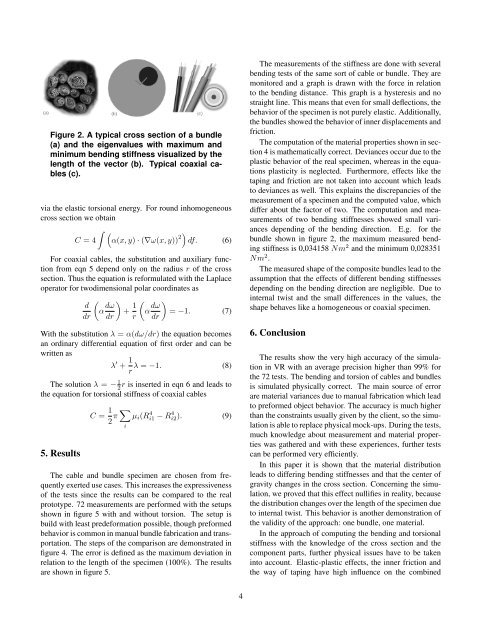
Figure 2. A typical cross section <strong>of</strong> a bundle<br />
(a) <strong>and</strong> the eigenvalues with maximum <strong>and</strong><br />
minimum bending stiffness visualized by the<br />
length <strong>of</strong> the vector (b). Typical coaxial cables<br />
(c).<br />
via the elastic torsional energy. For round inhomogeneous<br />
cross section we obtain<br />
� �<br />
C = 4 α(x, y) · (∇ω(x, y)) 2�<br />
df. (6)<br />
For coaxial cables, the substitution <strong>and</strong> auxiliary function<br />
from eqn 5 depend only on the radius r <strong>of</strong> the cross<br />
section. Thus the equation is re<strong>for</strong>mulated with the Laplace<br />
operator <strong>for</strong> twodimensional polar coordinates as<br />
�<br />
d<br />
α<br />
dr<br />
dω<br />
�<br />
+<br />
dr<br />
1<br />
�<br />
α<br />
r<br />
dω<br />
�<br />
= −1. (7)<br />
dr<br />
With the substitution λ = α(dω/dr) the equation becomes<br />
an ordinary differential equation <strong>of</strong> first order <strong>and</strong> can be<br />
written as<br />
λ ′ + 1<br />
λ = −1. (8)<br />
r<br />
The solution λ = − 1<br />
2r is inserted in eqn 6 <strong>and</strong> leads to<br />
the equation <strong>for</strong> torsional stiffness <strong>of</strong> coaxial cables<br />
5. Results<br />
C = 1 �<br />
π µi(R<br />
2 4 i1 − R 4 i2). (9)<br />
i<br />
The cable <strong>and</strong> bundle specimen are chosen from frequently<br />
exerted use cases. This increases the expressiveness<br />
<strong>of</strong> the tests since the results can be compared to the real<br />
prototype. 72 measurements are per<strong>for</strong>med with the setups<br />
shown in figure 5 with <strong>and</strong> without torsion. The setup is<br />
build with least prede<strong>for</strong>mation possible, though pre<strong>for</strong>med<br />
behavior is common in manual bundle fabrication <strong>and</strong> transportation.<br />
The steps <strong>of</strong> the comparison are demonstrated in<br />
figure 4. The error is defined as the maximum deviation in<br />
relation to the length <strong>of</strong> the specimen (100%). The results<br />
are shown in figure 5.<br />
4<br />
The measurements <strong>of</strong> the stiffness are done with several<br />
bending tests <strong>of</strong> the same sort <strong>of</strong> cable or bundle. They are<br />
monitored <strong>and</strong> a graph is drawn with the <strong>for</strong>ce in relation<br />
to the bending distance. This graph is a hysteresis <strong>and</strong> no<br />
straight line. This means that even <strong>for</strong> small deflections, the<br />
behavior <strong>of</strong> the specimen is not purely elastic. Additionally,<br />
the bundles showed the behavior <strong>of</strong> inner displacements <strong>and</strong><br />
friction.<br />
The computation <strong>of</strong> the material properties shown in section<br />
4 is mathematically correct. Deviances occur due to the<br />
plastic behavior <strong>of</strong> the real specimen, whereas in the equations<br />
plasticity is neglected. Furthermore, effects like the<br />
taping <strong>and</strong> friction are not taken into account which leads<br />
to deviances as well. This explains the discrepancies <strong>of</strong> the<br />
measurement <strong>of</strong> a specimen <strong>and</strong> the computed value, which<br />
differ about the factor <strong>of</strong> two. The computation <strong>and</strong> measurements<br />
<strong>of</strong> two bending stiffnesses showed small variances<br />
depending <strong>of</strong> the bending direction. E.g. <strong>for</strong> the<br />
bundle shown in figure 2, the maximum measured bending<br />
stiffness is 0,034158 Nm 2 <strong>and</strong> the minimum 0,028351<br />
Nm 2 .<br />
The measured shape <strong>of</strong> the composite bundles lead to the<br />
assumption that the effects <strong>of</strong> different bending stiffnesses<br />
depending on the bending direction are negligible. Due to<br />
internal twist <strong>and</strong> the small differences in the values, the<br />
shape behaves like a homogeneous or coaxial specimen.<br />
6. Conclusion<br />
The results show the very high accuracy <strong>of</strong> the simulation<br />
in VR with an average precision higher than 99% <strong>for</strong><br />
the 72 tests. The bending <strong>and</strong> torsion <strong>of</strong> cables <strong>and</strong> bundles<br />
is simulated physically correct. The main source <strong>of</strong> error<br />
are material variances due to manual fabrication which lead<br />
to pre<strong>for</strong>med object behavior. The accuracy is much higher<br />
than the constraints usually given by the client, so the simulation<br />
is able to replace physical mock-ups. During the tests,<br />
much knowledge about measurement <strong>and</strong> material properties<br />
was gathered <strong>and</strong> with these experiences, further tests<br />
can be per<strong>for</strong>med very efficiently.<br />
In this paper it is shown that the material distribution<br />
leads to differing bending stiffnesses <strong>and</strong> that the center <strong>of</strong><br />
gravity changes in the cross section. Concerning the simulation,<br />
we proved that this effect nullifies in reality, because<br />
the distribution changes over the length <strong>of</strong> the specimen due<br />
to internal twist. This behavior is another demonstration <strong>of</strong><br />
the validity <strong>of</strong> the approach: one bundle, one material.<br />
In the approach <strong>of</strong> computing the bending <strong>and</strong> torsional<br />
stiffness with the knowledge <strong>of</strong> the cross section <strong>and</strong> the<br />
component parts, further physical issues have to be taken<br />
into account. Elastic-plastic effects, the inner friction <strong>and</strong><br />
the way <strong>of</strong> taping have high influence on the combined