Simulation of wiring harnesses and hoses for product design ... - Icido
Simulation of wiring harnesses and hoses for product design ... - Icido
Simulation of wiring harnesses and hoses for product design ... - Icido

Create successful ePaper yourself
Turn your PDF publications into a flip-book with our unique Google optimized e-Paper software.
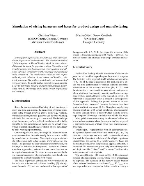
<strong>Simulation</strong> <strong>of</strong> <strong>wiring</strong> <strong>harnesses</strong> <strong>and</strong> <strong>hoses</strong> <strong>for</strong> <strong>product</strong> <strong>design</strong> <strong>and</strong> manufacturing<br />
Christian Wienss<br />
IC:IDO GmbH, Cologne, Germany<br />
christian.wienss@icido.com<br />
Abstract<br />
In this paper a physically accurate real time cable simulation<br />
is presented <strong>and</strong> validated. The simulation method<br />
is fully integrated in Virtual Reality, which increases the usability<br />
<strong>and</strong> the sense <strong>for</strong> physical realism. The influence <strong>of</strong><br />
prede<strong>for</strong>mation, non-homogeneous cross sections <strong>and</strong> different<br />
taping <strong>of</strong> the bundles will be analyzed <strong>and</strong> compared<br />
to the simulation. The simulation is validated with respect<br />
to the physical behavior <strong>of</strong> real cables <strong>and</strong> bundles. Material<br />
properties like stiffness <strong>and</strong> density are measured <strong>of</strong><br />
every specimen. To avoid further expensive measurements,<br />
a way to determine bending <strong>and</strong> torsional stiffness numerically<br />
with the knowledge <strong>of</strong> the cross section is presented<br />
<strong>and</strong> analyzed.<br />
1. Introduction<br />
Since the construction <strong>and</strong> building <strong>of</strong> real mock-ups is<br />
costly <strong>and</strong> time-consuming, the proportion <strong>of</strong> virtual simulation<br />
in the <strong>product</strong> life cycle grows. Today e.g. visibility,<br />
reachability <strong>and</strong> ergonomic questions can be dealt with long<br />
be<strong>for</strong>e the first real mock-up is constructed. The knowledge<br />
about the accuracy <strong>of</strong> the utilized simulation tool is indispensable<br />
<strong>for</strong> the substitution <strong>of</strong> mock-ups by virtual prototyping.<br />
The motion <strong>and</strong> behavior <strong>of</strong> stiff objects can already<br />
be dealt with high per<strong>for</strong>mance.<br />
Concerning flexible parts, the usage <strong>of</strong> simulation is not<br />
very common since the tools usually lack accuracy, usability<br />
or real-time per<strong>for</strong>mance. Non-physical representations<br />
like splines dominate today’s digital work with cables <strong>and</strong><br />
<strong>hoses</strong>. This provides the user with real-time interaction, but<br />
the physical behavior is disregarded. In order to contrast<br />
with these approaches, a simulation tool has to demonstrate<br />
its physical correctness. To prove accuracy, one needs the<br />
real material parameters <strong>of</strong> a real complex cable bundle <strong>and</strong><br />
compare the simulation results with reality.<br />
The focus <strong>of</strong> previous publications was concentrated on<br />
the real-time solution <strong>and</strong> collision h<strong>and</strong>ling [5], the dynamic<br />
behavior [2], <strong>and</strong> the mathematical background <strong>of</strong><br />
1<br />
Martin Göbel, Gernot Goebbels<br />
fleXilution GmbH<br />
Cologne, Germany<br />
the approach [8, 9, 5, 2]. In this paper, the accuracy <strong>of</strong> the<br />
system is tested <strong>and</strong> compared with reality. There<strong>for</strong>e, real<br />
use case setups <strong>and</strong> advanced trial setups are taken into account.<br />
2. Related Work<br />
Publications dealing with the simulation <strong>of</strong> flexible objects<br />
can be classified depending on the research progress.<br />
The first step is the approach itself with few optimizations<br />
[4, 8, 18]. If the idea is promising, the next goal is to obtain<br />
real-time per<strong>for</strong>mance <strong>for</strong> smaller segments <strong>and</strong> small<br />
examinations <strong>of</strong> the accuracy are done [14, 3, 17]. Now<br />
the simulation is embedded into some virtual environment,<br />
where additional functionality, usability <strong>and</strong> features are applied<br />
without great additions to the simulation core [7, 9].<br />
After that is successfully done, a <strong>product</strong> is developed out<br />
<strong>of</strong> this approach. Selling this <strong>product</strong> means to be confronted<br />
with the customers’ dem<strong>and</strong>s <strong>for</strong> interaction, integration<br />
<strong>and</strong> their use cases [5, 2]. To replace step by step<br />
physical mock-ups with virtual simulation, a high credibility<br />
<strong>of</strong> the simulation tool is needed which leads to the next<br />
step: the pro<strong>of</strong> <strong>of</strong> concept, which is dealt with in this paper.<br />
Most publications concerning simulation <strong>of</strong> cables <strong>and</strong><br />
<strong>hoses</strong> include sections where the accuracy <strong>of</strong> the approach<br />
is embraced, but none <strong>of</strong> them prove their correctness expressively.<br />
Theetten [16, 17] presents his work on geometrically exact<br />
dynamic splines <strong>and</strong> follows the ideas <strong>of</strong> [15, 10, 11].<br />
Here the comparison has been made between the simulation<br />
<strong>and</strong> the theoretical solution <strong>of</strong> the elliptic equations.<br />
Several loads are applied to a 4 meter cantilever beam <strong>and</strong><br />
the bending behavior <strong>of</strong> the presented approach (GEDS) is<br />
computed. No numbers are given, only a visual comparison<br />
<strong>and</strong> depictions like ”‘close”’ <strong>and</strong> ”‘accurate”’ with relation<br />
to the number <strong>of</strong> control points.<br />
The idea <strong>of</strong> Schotte [14], based on [13, 12, 1], is the modification<br />
<strong>of</strong> a mass-spring system, where <strong>for</strong>ces are replaced<br />
by impulses. The accuracy <strong>of</strong> this iterative model depends<br />
<strong>of</strong> the value <strong>of</strong> the distance condition Dmax. If Dmax is set<br />
to a large value, the computation is fast, but the accuracy is
low <strong>and</strong> vice versa. Un<strong>for</strong>tunately Schotte makes no validation<br />
<strong>of</strong> the results <strong>and</strong> only mentions the accuracy increases<br />
if Dmax is reduced.<br />
The approach <strong>of</strong> Grégoire <strong>and</strong> Schömer [3] is iterative as<br />
well <strong>and</strong> it is mentioned that several algorithms are used <strong>for</strong><br />
the best solution in position <strong>and</strong> energy. If a certain threshold<br />
is reached, the simulation finishes with this solution. A<br />
comparison to reality is made with one use case, a brake<br />
hose. No accuracy numbers are given, only a visual impression<br />
<strong>and</strong> the description ”‘good fitting”’. The determination<br />
<strong>of</strong> the material properties is done empirically. Grégoire <strong>and</strong><br />
Schömer mention the problem <strong>of</strong> prede<strong>for</strong>mation <strong>and</strong> supplementary<br />
torsion <strong>and</strong> relegate to construction tolerances.<br />
Linn et al. [7] present an approach based on Kirchh<strong>of</strong>f’s<br />
geometrical exact theory which is approximately solved by<br />
energy minimization using a nonlinear conjugate gradients<br />
method. It is mentioned that the algorithm is integrated in a<br />
s<strong>of</strong>tware package <strong>and</strong> the real-time capability is comparable<br />
to [3]. The accuracy is neither mentioned nor proved.<br />
3. Idea <strong>of</strong> Comparison<br />
In this paper, the published approach <strong>of</strong> a high accurate<br />
real time simulation <strong>of</strong> cables (fleXengine) [8, 5, 2] is compared<br />
with real cable setups. Since dynamic effects are difficult<br />
to measure, the first step ist to take the quasistatic behavior<br />
<strong>of</strong> our simulation tool into account. This is equivalent<br />
to the constraint that the system is at equilibrium after<br />
each time step <strong>and</strong> the energy is minimized.<br />
In the virtual scene, the accuracy <strong>of</strong> a cable simulation<br />
system can only be judged by the users’ sense <strong>of</strong> plausibility<br />
<strong>and</strong> experience. For many applications, this solution<br />
with real-time interaction is already feasible <strong>and</strong> leads to a<br />
reduction <strong>of</strong> prototypes. For further credibility, the accuracy<br />
<strong>of</strong> the simulation system has to be proved. In most cases, the<br />
comparison was made with numerical solutions [17] or simple<br />
curvature in reality (unpublished internal work). Complex<br />
curvature, gravity <strong>and</strong> torsional effects are not yet taken<br />
into account.<br />
There<strong>for</strong>e we composed <strong>and</strong> constructed a testing setup<br />
<strong>for</strong> complex cable <strong>and</strong> hose shapes (see fig. 1). Variable<br />
setups <strong>and</strong> torsions can be applied to the specimen up to a<br />
length <strong>of</strong> 1000 mm. The position <strong>and</strong> orientation <strong>of</strong> both<br />
sides is freely adjustable <strong>and</strong> on one side torsional <strong>for</strong>ces<br />
can be applied <strong>and</strong> measured. The cable specimen are<br />
braided cables from 1mm 2 to 10mm 2 , the bundle specimen<br />
homogeneous <strong>and</strong> composite bundles with different taping<br />
like spiral taped, half taped, conduit <strong>and</strong> full taped. A h<strong>and</strong><br />
held laser scanner digitizes the shape without influencing<br />
it at very high precision (0.1 mm resolution). The digital<br />
shape is then imported in the simulation system <strong>and</strong> the centerline<br />
is extracted. The simulation system is embedded into<br />
2<br />
the Visual Decision Plat<strong>for</strong>m developed by IC:IDO GmbH 1 .<br />
The s<strong>of</strong>tware is able to replace rigid geometry which represents<br />
a cable or hose with a flexible object. The algorithm<br />
is able to reconstruct the round shape <strong>of</strong> the specimen very<br />
precisely, even if the laser scan is highly fragmented. Thus<br />
the scanned object is replaced by a simulated object with a<br />
high number <strong>of</strong> supporting points (h<strong>and</strong>les) to fit the original<br />
shape with very high precision. The internal procedure<br />
<strong>of</strong> this algorithm is confidential, the accuracy <strong>of</strong> this method<br />
is seen in figure 4.<br />
The next step is the determination <strong>of</strong> material properties<br />
<strong>of</strong> the real cable. There<strong>for</strong>e the specimen is measured <strong>for</strong><br />
stiffness (Young’s Modulus) <strong>and</strong> density. The stiffness is<br />
determined by measuring the <strong>for</strong>ce that is needed to bend<br />
a defined length <strong>of</strong> the specimen <strong>for</strong> a given displacement.<br />
The stiffness measured by tensile test differs much from the<br />
bending test, which is due to the complex inner structure: a<br />
braided wire behaves in bending far s<strong>of</strong>ter than in the tensile<br />
test, where it behaves almost like a rod. Thus the tensile<br />
stiffness is up to 100 times higher. Since in most cases the<br />
simulation is build to simulate bending behavior <strong>and</strong> shapes,<br />
the bending stiffness is the parameter <strong>of</strong> choice. Density is<br />
measured with a pycnometer. Additionally, inner <strong>and</strong> outer<br />
diameter <strong>and</strong> the length <strong>of</strong> the specimen are measured.<br />
With the scanned shape <strong>of</strong> the specimen <strong>and</strong> the material<br />
properties, the simulation can be per<strong>for</strong>med. The end positions<br />
<strong>of</strong> the scanned shape are taken <strong>and</strong> the tangents are<br />
measured. The end positions, the tangents, the diameters,<br />
the length, the material properties <strong>and</strong> the knowledge about<br />
the direction <strong>of</strong> gravity are used as input parameters <strong>of</strong> the<br />
simulation. Since the positions are taken out <strong>of</strong> the laser<br />
scan, the optimal case would now be a high match <strong>of</strong> the<br />
scanned <strong>and</strong> the simulated shape. The centerlines are extracted<br />
<strong>and</strong> compared with NX 2 to measure the deviations<br />
with µm precision. The maximum deviation between the<br />
centerlines in relation with the length <strong>of</strong> the specimen is defined<br />
as the error <strong>of</strong> the analysis.<br />
4. Precomputation <strong>of</strong> Material Properties<br />
To increase the expressiveness <strong>of</strong> the comparison, the<br />
real material properties have to be measured. This leads<br />
to several difficulties in the daily use <strong>of</strong> the tool.<br />
1. Knowledge <strong>of</strong> components In early construction<br />
stages, a rough routing <strong>of</strong> the cable is needed. The<br />
knowledge <strong>of</strong> the final components is still dependent<br />
<strong>of</strong> the later usage <strong>of</strong> the bundle. Without the final construction<br />
idea, the bundle cannot be build <strong>and</strong> measured.<br />
1 www.icido.com<br />
2 http://www.ugsplm.de/produkte/nx/
Figure 1. The test setup <strong>for</strong> any possible combination<br />
<strong>of</strong> bending <strong>and</strong> torsion (a) with measurement<br />
system <strong>and</strong> scale <strong>for</strong> torque (b).<br />
The applied or risen torsion <strong>for</strong>ce can be read<br />
on the newton meter <strong>and</strong> related to the degree<br />
<strong>of</strong> rotation (c).<br />
2. Variants In the same <strong>product</strong>, the components <strong>of</strong> a cable<br />
bundle differ depending <strong>of</strong> the fitting. The bundle<br />
can contain e.g. three aerial cables or six or additional<br />
sensor cables <strong>for</strong> e.g. inflation status. Thus, plenty <strong>of</strong><br />
variants have to be measured.<br />
3. Need <strong>of</strong> accuracy Not every part <strong>of</strong> a flexible component<br />
is critical regarding the shape. Motion, critical<br />
obstacles <strong>and</strong> construction issues have to be h<strong>and</strong>led<br />
with high accuracy. If the environment is uncritical, a<br />
90%-solution might be adequate.<br />
4. Cost-Benefit The measurements are costly <strong>and</strong> the<br />
construction <strong>of</strong> the cable takes critical time.<br />
These considerations lead to the question if there is a faster<br />
<strong>and</strong> cheaper way <strong>for</strong> some use cases, where e.g. a 90%solution<br />
is adequate. There<strong>for</strong>e investigations have been<br />
made to compute the material parameters <strong>of</strong> a bundle with<br />
only the knowledge <strong>of</strong> the components. The material properties<br />
<strong>of</strong> the components have to be measured as well, but<br />
their number is more limited than the combinations. For the<br />
single str<strong>and</strong>s <strong>and</strong> their isolations the properties are known<br />
<strong>and</strong> filed in a material database.<br />
Known from beam theory [6], the bending stiffness (B)<br />
is given by the Young’s Module (E) <strong>and</strong> the moment <strong>of</strong> in-<br />
3<br />
ertia <strong>of</strong> area (I) by<br />
B = EI.<br />
I is defined as<br />
I = 1<br />
4 π(R4 1 − R 4 2),<br />
where R1 is the outer diameter <strong>and</strong> R2 the inner one regarding<br />
a hose. Since R2 is zero <strong>for</strong> cables, the equation <strong>for</strong> the<br />
bending stiffness reduces to<br />
B = 1<br />
4 πER4 .<br />
This equation is valid <strong>for</strong> homogeneous <strong>and</strong> circular<br />
cross sections. For composite cross sections, the center <strong>of</strong><br />
bending is no longer the center <strong>of</strong> the bundle since it is dependent<br />
<strong>of</strong> the material distribution. Thus two main axes<br />
<strong>of</strong> inertia are defined, which represent the minimum <strong>and</strong><br />
the maximum bending stress (see fig. 2, (a)). The cross<br />
sections are composed in an editor, where each color represents<br />
a defined stiffness (see fig. 2, (b)). These directions<br />
are obtained via the computation <strong>of</strong> the eigenvalues <strong>of</strong> the<br />
bending stiffness matrix<br />
� �<br />
Bxx Bxy<br />
Bij =<br />
, (1)<br />
Byx Byy<br />
which is computed by<br />
�<br />
Bij = E(�s)(s − s0)i(s − s0)jdf. (2)<br />
s <strong>and</strong> s0 are given in cross section coordinates. The moments<br />
<strong>of</strong> inertia are related to the center <strong>of</strong> bending which<br />
differs from the center <strong>of</strong> the bundle s0 <strong>and</strong> leads to the <strong>of</strong>fset<br />
s − s0.<br />
For coaxial cross sections eqn 2 can be transfered to polar<br />
coordinates <strong>and</strong> can be rewritten as<br />
�<br />
B = πrErr 2 dr. (3)<br />
This leads to the known <strong>and</strong> proved analytical solution<br />
<strong>for</strong> coaxial cross sections (see fig. 2, (c))<br />
B = �<br />
i<br />
1<br />
4 Eiπ(R 4 1i − R 4 2i). (4)<br />
The torsional stiffness is described with the shear modulus<br />
µ. For composite cross sections, µ is no longer constant<br />
but dependent on the position µ(x, y). Thus µ is partially<br />
differenced <strong>and</strong> with the auxiliary function χ (see [6]), <strong>and</strong><br />
the substitutions ω(x, y) = µχ <strong>and</strong> α(x, y) = 1<br />
µ we have<br />
�<br />
∂<br />
α<br />
∂x<br />
∂ω<br />
�<br />
+<br />
∂x<br />
∂<br />
�<br />
α<br />
∂y<br />
∂ω<br />
�<br />
= −1. (5)<br />
∂y<br />
By taking into account the boundary conditions <strong>for</strong> the edge<br />
h<strong>and</strong>ling (ω = 0), the torsional stiffness C can be computed
Figure 2. A typical cross section <strong>of</strong> a bundle<br />
(a) <strong>and</strong> the eigenvalues with maximum <strong>and</strong><br />
minimum bending stiffness visualized by the<br />
length <strong>of</strong> the vector (b). Typical coaxial cables<br />
(c).<br />
via the elastic torsional energy. For round inhomogeneous<br />
cross section we obtain<br />
� �<br />
C = 4 α(x, y) · (∇ω(x, y)) 2�<br />
df. (6)<br />
For coaxial cables, the substitution <strong>and</strong> auxiliary function<br />
from eqn 5 depend only on the radius r <strong>of</strong> the cross<br />
section. Thus the equation is re<strong>for</strong>mulated with the Laplace<br />
operator <strong>for</strong> twodimensional polar coordinates as<br />
�<br />
d<br />
α<br />
dr<br />
dω<br />
�<br />
+<br />
dr<br />
1<br />
�<br />
α<br />
r<br />
dω<br />
�<br />
= −1. (7)<br />
dr<br />
With the substitution λ = α(dω/dr) the equation becomes<br />
an ordinary differential equation <strong>of</strong> first order <strong>and</strong> can be<br />
written as<br />
λ ′ + 1<br />
λ = −1. (8)<br />
r<br />
The solution λ = − 1<br />
2r is inserted in eqn 6 <strong>and</strong> leads to<br />
the equation <strong>for</strong> torsional stiffness <strong>of</strong> coaxial cables<br />
5. Results<br />
C = 1 �<br />
π µi(R<br />
2 4 i1 − R 4 i2). (9)<br />
i<br />
The cable <strong>and</strong> bundle specimen are chosen from frequently<br />
exerted use cases. This increases the expressiveness<br />
<strong>of</strong> the tests since the results can be compared to the real<br />
prototype. 72 measurements are per<strong>for</strong>med with the setups<br />
shown in figure 5 with <strong>and</strong> without torsion. The setup is<br />
build with least prede<strong>for</strong>mation possible, though pre<strong>for</strong>med<br />
behavior is common in manual bundle fabrication <strong>and</strong> transportation.<br />
The steps <strong>of</strong> the comparison are demonstrated in<br />
figure 4. The error is defined as the maximum deviation in<br />
relation to the length <strong>of</strong> the specimen (100%). The results<br />
are shown in figure 5.<br />
4<br />
The measurements <strong>of</strong> the stiffness are done with several<br />
bending tests <strong>of</strong> the same sort <strong>of</strong> cable or bundle. They are<br />
monitored <strong>and</strong> a graph is drawn with the <strong>for</strong>ce in relation<br />
to the bending distance. This graph is a hysteresis <strong>and</strong> no<br />
straight line. This means that even <strong>for</strong> small deflections, the<br />
behavior <strong>of</strong> the specimen is not purely elastic. Additionally,<br />
the bundles showed the behavior <strong>of</strong> inner displacements <strong>and</strong><br />
friction.<br />
The computation <strong>of</strong> the material properties shown in section<br />
4 is mathematically correct. Deviances occur due to the<br />
plastic behavior <strong>of</strong> the real specimen, whereas in the equations<br />
plasticity is neglected. Furthermore, effects like the<br />
taping <strong>and</strong> friction are not taken into account which leads<br />
to deviances as well. This explains the discrepancies <strong>of</strong> the<br />
measurement <strong>of</strong> a specimen <strong>and</strong> the computed value, which<br />
differ about the factor <strong>of</strong> two. The computation <strong>and</strong> measurements<br />
<strong>of</strong> two bending stiffnesses showed small variances<br />
depending <strong>of</strong> the bending direction. E.g. <strong>for</strong> the<br />
bundle shown in figure 2, the maximum measured bending<br />
stiffness is 0,034158 Nm 2 <strong>and</strong> the minimum 0,028351<br />
Nm 2 .<br />
The measured shape <strong>of</strong> the composite bundles lead to the<br />
assumption that the effects <strong>of</strong> different bending stiffnesses<br />
depending on the bending direction are negligible. Due to<br />
internal twist <strong>and</strong> the small differences in the values, the<br />
shape behaves like a homogeneous or coaxial specimen.<br />
6. Conclusion<br />
The results show the very high accuracy <strong>of</strong> the simulation<br />
in VR with an average precision higher than 99% <strong>for</strong><br />
the 72 tests. The bending <strong>and</strong> torsion <strong>of</strong> cables <strong>and</strong> bundles<br />
is simulated physically correct. The main source <strong>of</strong> error<br />
are material variances due to manual fabrication which lead<br />
to pre<strong>for</strong>med object behavior. The accuracy is much higher<br />
than the constraints usually given by the client, so the simulation<br />
is able to replace physical mock-ups. During the tests,<br />
much knowledge about measurement <strong>and</strong> material properties<br />
was gathered <strong>and</strong> with these experiences, further tests<br />
can be per<strong>for</strong>med very efficiently.<br />
In this paper it is shown that the material distribution<br />
leads to differing bending stiffnesses <strong>and</strong> that the center <strong>of</strong><br />
gravity changes in the cross section. Concerning the simulation,<br />
we proved that this effect nullifies in reality, because<br />
the distribution changes over the length <strong>of</strong> the specimen due<br />
to internal twist. This behavior is another demonstration <strong>of</strong><br />
the validity <strong>of</strong> the approach: one bundle, one material.<br />
In the approach <strong>of</strong> computing the bending <strong>and</strong> torsional<br />
stiffness with the knowledge <strong>of</strong> the cross section <strong>and</strong> the<br />
component parts, further physical issues have to be taken<br />
into account. Elastic-plastic effects, the inner friction <strong>and</strong><br />
the way <strong>of</strong> taping have high influence on the combined
Figure 3. Three setups used <strong>for</strong> the validation.<br />
The test were per<strong>for</strong>med with no torsion<br />
<strong>and</strong> 45 ◦ or 90 ◦ torsion.<br />
Figure 4. The laser scan <strong>of</strong> the specimen (a),<br />
the reconstruction <strong>of</strong> the centerline <strong>of</strong> the<br />
specimen (b, c), the simulation result (d) <strong>and</strong><br />
the comparison with NX.<br />
5<br />
Figure 5. From 72 specimen, the error <strong>of</strong> 50<br />
test is below 1%. The main source <strong>of</strong> error<br />
(3% <strong>and</strong> 4%) is related to prede<strong>for</strong>mation.<br />
This proves the high accuracy <strong>of</strong> the simulation<br />
<strong>and</strong> the correctness <strong>of</strong> the measurement<br />
<strong>of</strong> the material properties.<br />
properties <strong>of</strong> the specimen. This sector will be <strong>of</strong> high interest<br />
<strong>for</strong> further research projects.<br />
7. Acknowledgments<br />
Thanks to Delphi Packard <strong>for</strong> specimen <strong>and</strong> funding.<br />
References<br />
[1] J. Bender, M. Baas, <strong>and</strong> A. Schmitt. Ein neues verfahren<br />
für die mechanische simulation in vr-systemen und in der<br />
robotik, universität karlsruhe, 2003.<br />
[2] G. Goebbels, M. Göbel, T. Hambürger, N. Hornung,<br />
U. Klein, I. Nikitin, O. Rattay, J. Scharping, K. Troche, <strong>and</strong><br />
C. Wienss. Realtime dynamics simulation <strong>of</strong> cables, <strong>hoses</strong><br />
<strong>and</strong> <strong>wiring</strong> <strong>harnesses</strong> <strong>for</strong> high accuracy digital mockups <strong>and</strong><br />
load analysis. In Proceedings <strong>of</strong> the Conference Automotive<br />
Power Electronics Paris - Salons de l’Aveyron (APE), Paris,<br />
France, 2007. Socit des Ingnieurs de l’ Automobile (SIA).<br />
[3] M. Gregoire <strong>and</strong> E. Schömer. Interactive simulation <strong>of</strong> onedimensional<br />
flexible parts. Comput. Aided Des., 39(8):694–<br />
707, 2007.<br />
[4] E. Hergenröther <strong>and</strong> S. Müller. Integration <strong>of</strong> cables in the<br />
virtual <strong>product</strong> development process. In PROLAMAT, pages<br />
84–94, 2001.<br />
[5] N. Hornung, I. Nikitin, G. Goebbels, U. Klein, S. Müller,<br />
<strong>and</strong> C. Wienss. flexengine: Highly accurate real-time simulation<br />
system <strong>for</strong> cables, <strong>hoses</strong> <strong>and</strong> <strong>wiring</strong> <strong>harnesses</strong> with<br />
contacts. In Proceedings <strong>of</strong> the International Wire <strong>and</strong> Cable<br />
Symposium (IWCS), Inc., pages 91–97, Providence, Rhode<br />
Isl<strong>and</strong>, USA, 2006. International Wire <strong>and</strong> Cable Symposium<br />
(IWCS), Inc.
[6] L. D. L<strong>and</strong>au <strong>and</strong> E. M. Lifschitz. Elastizitätstheorie. Number<br />
Bd. 7 in Lehrbuch der theoretischen Physik,. Akademie<br />
Verlag, Berlin, 7. auflage edition, 1991.<br />
[7] J. Linn, T. Stephan, J. Carlson, <strong>and</strong> R. Bohlin. Fast simulation<br />
<strong>of</strong> quasistatic rod de<strong>for</strong>mations <strong>for</strong> vr applications. In<br />
Progress in Industrial Mathematics, ECMI, pages 247–253.<br />
Springer, 2006.<br />
[8] I. Nikitin, L. Nikitina, P. Frolov, G. Goebbels, M. Goebel,<br />
S. Klimenko, <strong>and</strong> G. Nielson. Real-time simulation <strong>of</strong><br />
elastic objects in virtual environments using finite element<br />
method <strong>and</strong> precomputed green’s functions. In Eighth Eurographics<br />
Workshop on Virtual Environments, pages 47–52.<br />
Eurographics Association, 2002.<br />
[9] L. Nikitina, I. N. Nikitin, <strong>and</strong> S. V. Klimenko. Flexible materials<br />
in avangoTM virtual environment framework. In Computer<br />
Graphics International, pages 84–89. IEEE Computer<br />
Society, 2003.<br />
[10] H. Qin <strong>and</strong> D. Terzopoulos. Dynamic NURBS swung surfaces<br />
<strong>for</strong> physics-based shape <strong>design</strong>. Computer-aided Design,<br />
27(2):111–127, 1995.<br />
[11] H. Qin <strong>and</strong> D. Terzopoulos. D-NURBS: A Physics-Based<br />
Framework <strong>for</strong> Geometric Design. IEEE Transactions on<br />
Visualization <strong>and</strong> Computer Graphics, 2(1):85–96, 1996.<br />
[12] A. Schmitt. Dynamische <strong>Simulation</strong> von gelenkgekoppelten<br />
Starrkrpersystemen mit der Impulstechnik, Universitt Karlsruhe.<br />
2003.<br />
[13] A. Schmitt <strong>and</strong> S. Thüring. Ein vereinfachtes numerisches<br />
Verfahren für die mechanische <strong>Simulation</strong> in Virtual-Reality-<br />
Systemen, Universität Karlsruhe. 2000.<br />
[14] W. Schotte. <strong>Simulation</strong>desdynamischen verhaltens von kabeln<br />
für einbau-montage-simulation in vr. Master’s thesis,<br />
Fraunh<strong>of</strong>er IGD, Darmstadt, Germany, 2005.<br />
[15] D. Terzopoulos <strong>and</strong> H. Qin. Dynamic NURBS with geometric<br />
constraints <strong>for</strong> interactive sculpting. ACM Transactions<br />
on Graphics, 13(2):103–136, 1994.<br />
[16] A. Theetten, L. Grisoni, C. Andriot, <strong>and</strong> B. Barsky. Geometrically<br />
exact dynamic splines. INRIA Futurs, Rapport de<br />
recherche, 2006.<br />
[17] A. Theetten, L. Grisoni, C. Duriez, <strong>and</strong> X. Merlhiot. Quasidynamic<br />
splines. In SPM ’07: Proceedings <strong>of</strong> the 2007 ACM<br />
symposium on Solid <strong>and</strong> physical modeling, pages 409–414,<br />
New York, NY, USA, 2007. ACM Press.<br />
[18] C. Wienss, G. Goebbels, I. Nikitin, <strong>and</strong> S. Müller. Echtzeitde<strong>for</strong>mation<br />
und kollisionserkennung zur virtuellen operationssimulation.<br />
In Proceedings des 2. Workshops Virtuelle<br />
und Erweiterte Realität, pages 25–36. GI-Fachgruppe<br />
VR/AR, 2005.<br />
6