Interference Effects on Galileo E5b and E6 Frequen- cies ... - IFEN
Interference Effects on Galileo E5b and E6 Frequen- cies ... - IFEN
Interference Effects on Galileo E5b and E6 Frequen- cies ... - IFEN

Create successful ePaper yourself
Turn your PDF publications into a flip-book with our unique Google optimized e-Paper software.
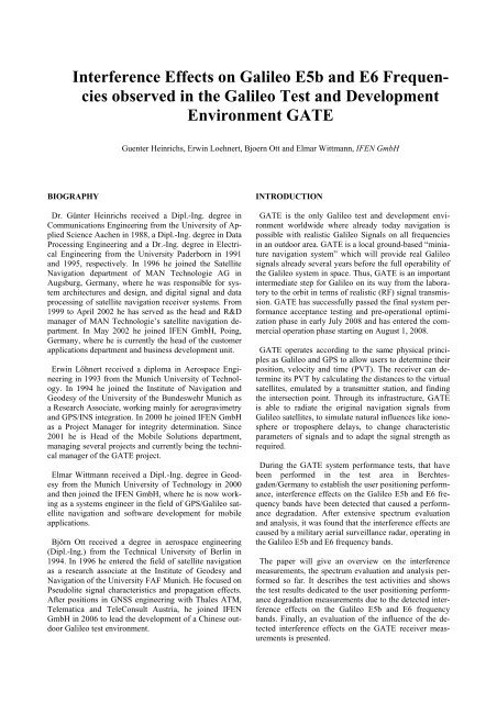
<str<strong>on</strong>g>Interference</str<strong>on</strong>g> <str<strong>on</strong>g>Effects</str<strong>on</strong>g> <strong>on</strong> <strong>Galileo</strong> <strong>E5b</strong> <strong>and</strong> <strong>E6</strong> <strong>Frequen</strong><strong>cies</strong><br />
observed in the <strong>Galileo</strong> Test <strong>and</strong> Development<br />
Envir<strong>on</strong>ment GATE<br />
BIOGRAPHY<br />
Guenter Heinrichs, Erwin Loehnert, Bjoern Ott <strong>and</strong> Elmar Wittmann, <strong>IFEN</strong> GmbH<br />
Dr. Günter Heinrichs received a Dipl.-Ing. degree in<br />
Communicati<strong>on</strong>s Engineering from the University of Applied<br />
Science Aachen in 1988, a Dipl.-Ing. degree in Data<br />
Processing Engineering <strong>and</strong> a Dr.-Ing. degree in Electrical<br />
Engineering from the University Paderborn in 1991<br />
<strong>and</strong> 1995, respectively. In 1996 he joined the Satellite<br />
Navigati<strong>on</strong> department of MAN Technologie AG in<br />
Augsburg, Germany, where he was resp<strong>on</strong>sible for system<br />
architectures <strong>and</strong> design, <strong>and</strong> digital signal <strong>and</strong> data<br />
processing of satellite navigati<strong>on</strong> receiver systems. From<br />
1999 to April 2002 he has served as the head <strong>and</strong> R&D<br />
manager of MAN Technologie’s satellite navigati<strong>on</strong> department.<br />
In May 2002 he joined <strong>IFEN</strong> GmbH, Poing,<br />
Germany, where he is currently the head of the customer<br />
applicati<strong>on</strong>s department <strong>and</strong> business development unit.<br />
Erwin Löhnert received a diploma in Aerospace Engineering<br />
in 1993 from the Munich University of Technology.<br />
In 1994 he joined the Institute of Navigati<strong>on</strong> <strong>and</strong><br />
Geodesy of the University of the Bundeswehr Munich as<br />
a Research Associate, working mainly for aerogravimetry<br />
<strong>and</strong> GPS/INS integrati<strong>on</strong>. In 2000 he joined <strong>IFEN</strong> GmbH<br />
as a Project Manager for integrity determinati<strong>on</strong>. Since<br />
2001 he is Head of the Mobile Soluti<strong>on</strong>s department,<br />
managing several projects <strong>and</strong> currently being the technical<br />
manager of the GATE project.<br />
Elmar Wittmann received a Dipl.-Ing. degree in Geodesy<br />
from the Munich University of Technology in 2000<br />
<strong>and</strong> then joined the <strong>IFEN</strong> GmbH, where he is now working<br />
as a systems engineer in the field of GPS/<strong>Galileo</strong> satellite<br />
navigati<strong>on</strong> <strong>and</strong> software development for mobile<br />
applicati<strong>on</strong>s.<br />
Björn Ott received a degree in aerospace engineering<br />
(Dipl.-Ing.) from the Technical University of Berlin in<br />
1994. In 1996 he entered the field of satellite navigati<strong>on</strong><br />
as a research associate at the Institute of Geodesy <strong>and</strong><br />
Navigati<strong>on</strong> of the University FAF Munich. He focused <strong>on</strong><br />
Pseudolite signal characteristics <strong>and</strong> propagati<strong>on</strong> effects.<br />
After positi<strong>on</strong>s in GNSS engineering with Thales ATM,<br />
Telematica <strong>and</strong> TeleC<strong>on</strong>sult Austria, he joined <strong>IFEN</strong><br />
GmbH in 2006 to lead the development of a Chinese outdoor<br />
<strong>Galileo</strong> test envir<strong>on</strong>ment.<br />
INTRODUCTION<br />
GATE is the <strong>on</strong>ly <strong>Galileo</strong> test <strong>and</strong> development envir<strong>on</strong>ment<br />
worldwide where already today navigati<strong>on</strong> is<br />
possible with realistic <strong>Galileo</strong> Signals <strong>on</strong> all frequen<strong>cies</strong><br />
in an outdoor area. GATE is a local ground-based “miniature<br />
navigati<strong>on</strong> system” which will provide real <strong>Galileo</strong><br />
signals already several years before the full operability of<br />
the <strong>Galileo</strong> system in space. Thus, GATE is an important<br />
intermediate step for <strong>Galileo</strong> <strong>on</strong> its way from the laboratory<br />
to the orbit in terms of realistic (RF) signal transmissi<strong>on</strong>.<br />
GATE has successfully passed the final system performance<br />
acceptance testing <strong>and</strong> pre-operati<strong>on</strong>al optimizati<strong>on</strong><br />
phase in early July 2008 <strong>and</strong> has entered the commercial<br />
operati<strong>on</strong> phase starting <strong>on</strong> August 1, 2008.<br />
GATE operates according to the same physical principles<br />
as <strong>Galileo</strong> <strong>and</strong> GPS to allow users to determine their<br />
positi<strong>on</strong>, velocity <strong>and</strong> time (PVT). The receiver can determine<br />
its PVT by calculating the distances to the virtual<br />
satellites, emulated by a transmitter stati<strong>on</strong>, <strong>and</strong> finding<br />
the intersecti<strong>on</strong> point. Through its infrastructure, GATE<br />
is able to radiate the original navigati<strong>on</strong> signals from<br />
<strong>Galileo</strong> satellites, to simulate natural influences like i<strong>on</strong>osphere<br />
or troposphere delays, to change characteristic<br />
parameters of signals <strong>and</strong> to adapt the signal strength as<br />
required.<br />
During the GATE system performance tests, that have<br />
been performed in the test area in Berchtesgaden/Germany<br />
to establish the user positi<strong>on</strong>ing performance,<br />
interference effects <strong>on</strong> the <strong>Galileo</strong> <strong>E5b</strong> <strong>and</strong> <strong>E6</strong> frequency<br />
b<strong>and</strong>s have been detected that caused a performance<br />
degradati<strong>on</strong>. After extensive spectrum evaluati<strong>on</strong><br />
<strong>and</strong> analysis, it was found that the interference effects are<br />
caused by a military aerial surveillance radar, operating in<br />
the <strong>Galileo</strong> <strong>E5b</strong> <strong>and</strong> <strong>E6</strong> frequency b<strong>and</strong>s.<br />
The paper will give an overview <strong>on</strong> the interference<br />
measurements, the spectrum evaluati<strong>on</strong> <strong>and</strong> analysis performed<br />
so far. It describes the test activities <strong>and</strong> shows<br />
the test results dedicated to the user positi<strong>on</strong>ing performance<br />
degradati<strong>on</strong> measurements due to the detected interference<br />
effects <strong>on</strong> the <strong>Galileo</strong> <strong>E5b</strong> <strong>and</strong> <strong>E6</strong> frequency<br />
b<strong>and</strong>s. Finally, an evaluati<strong>on</strong> of the influence of the detected<br />
interference effects <strong>on</strong> the GATE receiver measurements<br />
is presented.
GATE INFRASTRUCTURE & TEST AREA<br />
GATE System Architecture<br />
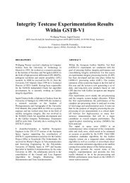
The GATE system is partiti<strong>on</strong>ed into four segments -<br />
Transmit Segment (GATS), Missi<strong>on</strong> Segment (GAMS),<br />
C<strong>on</strong>trol Segment (GCS), <strong>and</strong> the Support Segment. Figure<br />
1 presents an overview of the GATE system architecture.<br />
GTF<br />
Timing<br />
Facility<br />
GMCF<br />
C<strong>on</strong>trol Segment<br />
GPS<br />
GMS<br />
GPF<br />
GAMS<br />
SIS<br />
Missi<strong>on</strong> Support<br />
Facility<br />
Steering<br />
Ground (Field) Segment<br />
Support Segment<br />
<strong>Galileo</strong> IOV<br />
6 Transmit<br />
Stati<strong>on</strong>s<br />
GATS<br />
User Trajectory<br />
GATE<br />
User Receiver<br />
Figure 1: GATE Infrastructure Overview<br />
User<br />
GSTB<br />
GIOVE<br />
The ground-based transmitters, which are part of the<br />
GATE Transmit Segment (GATS), emit signals <strong>on</strong> all<br />
<strong>Galileo</strong> frequen<strong>cies</strong>. They are flexible in signal generati<strong>on</strong><br />
<strong>and</strong> adaptive to changes in signal structure. As<br />
GATE is a real-time system, it is necessary to feed the<br />
navigati<strong>on</strong> message in real-time to the transmitters. They<br />
are also equipped with stable atomic clocks.<br />
The GATE Missi<strong>on</strong> Segment (GAMS) m<strong>on</strong>itors the<br />
navigati<strong>on</strong> signals by using two GATE M<strong>on</strong>itoring Stati<strong>on</strong>s<br />
(GMS), performs the time synchr<strong>on</strong>isati<strong>on</strong> of all<br />
system clocks <strong>and</strong> generates navigati<strong>on</strong> messages <strong>and</strong><br />
steering comm<strong>and</strong>s to be sent to the six transmitters. The<br />
tasks denoted above are mainly performed by the two<br />
GAMS core elements, the GATE Processing Facility<br />
(GPF) <strong>and</strong> the GATE M<strong>on</strong>itor Receivers (GMRx), both<br />
developed by <strong>IFEN</strong> GmbH.<br />
The GATE C<strong>on</strong>trol Segment (GCS) includes all the<br />
functi<strong>on</strong>ality <strong>and</strong> facilities that are required for the missi<strong>on</strong><br />
c<strong>on</strong>trol <strong>and</strong> operati<strong>on</strong>. The main tasks are to m<strong>on</strong>itor<br />
<strong>and</strong> c<strong>on</strong>trol the entire GATE system, to host <strong>and</strong> operate<br />
the c<strong>on</strong>trol centre, to provide accurate <strong>and</strong> stable GATE<br />
system time aligned with TAI, <strong>and</strong> to archive GATE missi<strong>on</strong><br />
data.<br />
The main tasks of the GATE Support Segment (GSS)<br />
finally comprise the appropriate preparati<strong>on</strong>, i.e. simulati<strong>on</strong><br />
<strong>and</strong> planning, of the GATE experiments with dedicated<br />
software tools, as well as the provisi<strong>on</strong> of the<br />
GATE User Terminals equipped with a combined <strong>Galileo</strong>/GPS<br />
receiver.<br />
GATE Test Area Berchtesgaden / Germany<br />
The GATE test area is located in the regi<strong>on</strong> of Berchtesgaden<br />
in the very south-eastern part of Germany / Bavaria.<br />
The service area is depicted in the maps shown in<br />
Figure 2 a <strong>and</strong> b. The GATE test area, which is roughly<br />
limited by the imaginary c<strong>on</strong>necti<strong>on</strong> lines between the<br />
signal transmitters, has a size of about 65 km², while the<br />
GATE core test area, as marked in Figure 2 b, is about 25<br />
km². The two m<strong>on</strong>itoring stati<strong>on</strong>s are located at an exposed<br />
central site GATE test area. As can be seen <strong>on</strong> figure<br />
2c, Berchtesgaden is surrounded by high mountains,<br />
that are rising up to over 2000m. The installati<strong>on</strong> of the<br />
GATE transmitters <strong>on</strong> well exposed positi<strong>on</strong>s allows for<br />
emissi<strong>on</strong> of the GATE signals with average elevati<strong>on</strong><br />
angles between 10 to 15 degrees from a user’s point of<br />
view, when located within the GATE test area.<br />
Figure 2 a, b, c: GATE Service Area Berchtesgaden / Germany (core test area marked in red, transmitters<br />
marked as red dots) <strong>and</strong> view into the GATE test area
INTERFERENCE MEASUREMENT SET-UP IN<br />
THE GATE TEST AREA<br />
In the framework of the GATE system AIV (Assembly,<br />
Integrati<strong>on</strong> <strong>and</strong> Verificati<strong>on</strong>) activities extensive system<br />
tests have been performed for all three operati<strong>on</strong>al GATE<br />
modes, i.e. the Base Mode (BM), the Extended Base<br />
Mode (EBM) <strong>and</strong> the Virtual Satellite Mode (VSM). In<br />
BM the actual GTS positi<strong>on</strong>s are transmitted in the navigati<strong>on</strong><br />
message at c<strong>on</strong>stant power levels, this means the<br />
transmit platforms act like pseudolites. In EBM the Base<br />
Mode is extended by a dynamic adjustment of the signal<br />
power levels according to the current user positi<strong>on</strong>, which<br />
is fed back into the system via data link. In VSM a virtual<br />
dynamic <strong>Galileo</strong> satellite c<strong>on</strong>stellati<strong>on</strong> is emulated. The<br />
Doppler shift <strong>and</strong> power levels of the transmitters are<br />
steered to be identical with signals coming from orbit.<br />
For the evaluati<strong>on</strong> of the system performance within the<br />
GATE core area a test vehicle equipped with the GATE<br />
user receiver <strong>and</strong> terminal was used. With this vehicle<br />
static system tests as well as dynamic tests can be performed.<br />
In order to provide an independent <strong>and</strong> very accurate<br />
positi<strong>on</strong> reference a GPS RTK soluti<strong>on</strong> was applied<br />
using high-precisi<strong>on</strong> differential correcti<strong>on</strong>s. The<br />
accuracy of the RTK positi<strong>on</strong>s was typically in the range<br />
of a few centimetres in static scenarios <strong>and</strong> several decimetres<br />
within dynamic tests. In this way it is made sure<br />
that <strong>on</strong> the <strong>on</strong>e h<strong>and</strong> the steering of the signal transmitters<br />
in the Extended Base Mode <strong>and</strong> Virtual Satellite Mode is<br />
adjusted properly. On the other h<strong>and</strong> the precise RTK<br />
positi<strong>on</strong> serves as a reliable reference for the performance<br />
evaluati<strong>on</strong> with respect to the absolute GATE accuracy<br />
achieved.<br />
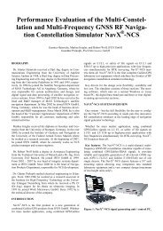
The GATE user receiver as well as a dual-frequency<br />
GPS RTK receiver for the positi<strong>on</strong> reference were installed<br />
in the test vehicle (see Figure 3). On the roof of<br />
the van two separate antennas for the receivers were<br />
mounted close to each other.<br />
Figure 3: GATE test vehicle <strong>and</strong> test setup<br />
Various tests with durati<strong>on</strong> of at least eight hours have<br />
been performed for the three different GATE modes in<br />
order to verify both, system stability <strong>and</strong> performance<br />
during the maximum daily operating time specified.<br />
The results obtained from these tests gave proof of the<br />
compliance of the GATE system with the performance<br />
specificati<strong>on</strong>s, at least for the E1 b<strong>and</strong>. The GATE specificati<strong>on</strong><br />
for the horiz<strong>on</strong>tal real-time navigati<strong>on</strong> requests a<br />
positi<strong>on</strong>ing accuracy with GATE signals better than 10 m<br />
(2 sigma) with an adequate HDOP (Horiz<strong>on</strong>tal Dilluti<strong>on</strong><br />
of Precisi<strong>on</strong>) value. The tests showed that this accuracy<br />
can also be achieved with the E5a <strong>and</strong> <strong>E5b</strong> signals, however,<br />
often some degradati<strong>on</strong>s of the positi<strong>on</strong>ing performance<br />
were observed for these frequen<strong>cies</strong>. Some sample<br />
results of the static GATE positi<strong>on</strong>ing tests are presented<br />
in figures 10, 11 <strong>and</strong> 12. After various analyzes of the E5<br />
test results there was clear evidence to suggest that those<br />
degradati<strong>on</strong>s may be caused by signal interference within<br />
the E5 b<strong>and</strong>.<br />
Thus, intensive investigati<strong>on</strong>s were made with respect to<br />
potential GATE/<strong>Galileo</strong> interference sources in the area<br />
of Berchtesgaden <strong>and</strong> surroundings. In the scope of these<br />
analyses several measurement campaigns were performed<br />
in order to detect potential interference sources as well as<br />
to evaluate the impact of interference sources already<br />
identified. Measurements have been performed by <strong>IFEN</strong><br />
GmbH <strong>and</strong> by the Bundesnetzagentur BNetzA (German<br />
Federal Network Agency), which is resp<strong>on</strong>sible for securing<br />
efficient <strong>and</strong> interference-free use of frequen<strong>cies</strong> in<br />
Germany.<br />
Figure 4 a, b: The BNetzA measuring vehicle during<br />
interference measurements in the GATE area<br />
At the GATE M<strong>on</strong>itoring Stati<strong>on</strong> (GMS) a spectrum<br />
analyzer <strong>and</strong> digital oscilloscope were c<strong>on</strong>nected to <strong>on</strong>e<br />
GMS antenna <strong>and</strong> the relevant frequency b<strong>and</strong>s were<br />
scanned. For the mobile interference measurements in the<br />
area of Berchtesgaden <strong>and</strong> surroundings, the test car was<br />
additi<strong>on</strong>ally equipped with a directi<strong>on</strong>al antenna which<br />
was c<strong>on</strong>nected to the measurement devices.<br />
In additi<strong>on</strong> to this measurement campaign the German<br />
Federal Network Agency (BNetzA) performed several<br />
measurements with its specially equipped measurement<br />
vehicle in the area of Berchtesgaden. Figure 4 shows this<br />
vehicle equipped with a telescopic antenna mast during
static measurements close to the GMS locati<strong>on</strong> (4a) <strong>and</strong><br />
at the GATE central point (4b).<br />
INTERFERENCE MEASUREMENT AND SPEC-<br />
TRUM EVALUATION RESULTS IN GATE<br />
Analysis of the spectrum analyzer measurements for the<br />
<strong>Galileo</strong> frequen<strong>cies</strong> showed that interference signals are<br />
present just outside of the ITU-reserved E5 b<strong>and</strong> <strong>and</strong><br />
right within the <strong>E6</strong> b<strong>and</strong>. The interference signals exhibited<br />
quite similar characteristics <strong>on</strong> two frequen<strong>cies</strong> of<br />
interest:<br />
E5 b<strong>and</strong>:<br />
- center frequency: 1217 MHz<br />
- “always <strong>on</strong>”<br />
<strong>E6</strong> b<strong>and</strong>:<br />
- center frequency: 1290 MHz<br />
- “sporadic presence”<br />
Comm<strong>on</strong><br />
- measured b<strong>and</strong>width: > 5 MHz<br />
- pulse spectral power: ca. –75 dBm<br />
- complex pulse sequence <strong>and</strong> shaping<br />
- average PDC: ~ 5%<br />
The 1217 MHz signal is c<strong>on</strong>stantly present, while the<br />
1290 MHz signal is <strong>on</strong>ly present at certain times of the<br />
day. After clear recepti<strong>on</strong> for a couple of hours, the signal<br />
ceases for another couple of hours, <strong>and</strong> then comes back.<br />
There are indicati<strong>on</strong>s the signal is switched to other frequen<strong>cies</strong><br />
meanwhile. No obvious schedule for this characteristic<br />
could be established.<br />
Snapshots of the interference signals observed at the<br />
spectrum analyzer are depicted in Figure 5 below (E5 in<br />
Fig. 5a <strong>and</strong> <strong>E6</strong> in Fig. 5b).<br />
Figure 5 a, b: <str<strong>on</strong>g>Interference</str<strong>on</strong>g> signals observed at GATE<br />
m<strong>on</strong>itoring stati<strong>on</strong><br />
The interference signals received at the GMS have then<br />
been analyzed in the time domain. Figure 6 shows the E5<br />
recurring pulse sequence. The pulse sequence is rather<br />
complex with pulses of variable durati<strong>on</strong> from 50 to 200<br />
microsec<strong>on</strong>ds.<br />
Each of the pulses is itself shaped in a n<strong>on</strong>-repetitious<br />
form. An enlarged representati<strong>on</strong> of a single 200 microsec<strong>on</strong>d<br />
pulse is presented in Figure 7. The pulse gaps are<br />
1.6 ms <strong>and</strong> 3.5 ms respectively. A 24.7 ms l<strong>on</strong>g sequence<br />
of 8 short pulses <strong>and</strong> 3 l<strong>on</strong>g pulses is repeated c<strong>on</strong>tinuously.<br />
Figure 7 also illustrates the signal measurements in<br />
the receiver fr<strong>on</strong>t-end.<br />
Figure 6: interference pulse sequence <strong>on</strong> E5<br />
The signal displayed green was measured before the<br />
AGC (Automatic Gain C<strong>on</strong>trol) amplifier <strong>and</strong> the <strong>on</strong>e<br />
shown in pink after AGC. The latter gives clear evidence<br />
of the AGC going into compressi<strong>on</strong> during the pulse.<br />
Essentially what happens is pulse clipping in the analog<br />
domain. This is a desirable effect because the total power<br />
entering the next stage, the A/D c<strong>on</strong>verter (ADC), is limited.<br />
An el<strong>on</strong>gati<strong>on</strong> of the pulse due to discharging of<br />
capacitors in the RF system after it has been driven into<br />
saturati<strong>on</strong> (recovery time) is not evident in Figure 7.<br />
Figure 7: E5 interference “l<strong>on</strong>g” pulse<br />
In additi<strong>on</strong> to the characteristics described above, the<br />
received interference signal exhibited a superimposed<br />
10 sec<strong>on</strong>d oscillati<strong>on</strong>. The 10 sec<strong>on</strong>d interval is assumed<br />
to stem from a rotating transmissi<strong>on</strong> antenna, which is<br />
typical for a radar installati<strong>on</strong>. The overall signal characteristics<br />
let us assume that the interference is emitted by a<br />
military l<strong>on</strong>g range air surveillance radar. The pulse durati<strong>on</strong><br />
is l<strong>on</strong>ger <strong>and</strong> pulse complexity higher than that of<br />
civil ATC radar (whose characteristics are rather well<br />
known).<br />
Figure 8 shows an example of a “typical” l<strong>on</strong>g range<br />
ATC radar interference signal. It was measured in the<br />
vicinity of a civil ATC radar stati<strong>on</strong> (Maitenbeth, GER)<br />
using the same test setup as described above.
Figure 8: Signal pulses of civil ATC radar<br />
Characteristics of this ATC radar simple pulse pair are<br />
- Pulse length 2 µsec<br />
- Pulse gap 2.5 µsec<br />
- Pulse repetiti<strong>on</strong> 1.9 to 2.6 msec<br />
- Center frequency 1259 MHz<br />
- Observed spectrum 27.5 MHz wide<br />
The results of the corresp<strong>on</strong>ding interference measurements<br />
performed by the BNetzA largely c<strong>on</strong>firmed the<br />
observati<strong>on</strong>s described above. The analysis of the<br />
BNetzA campaigns can be summarized as follows:<br />
- E5 b<strong>and</strong> (1155-1228 MHz): An interference spectrum<br />
with centre frequency 1217 MHz was detected<br />
- <strong>E6</strong> b<strong>and</strong> (1258 – 1300 MHz): An interference spectrum<br />
with centre frequency 1290 MHz was detected.<br />
- Main result of the analysis according to BNetzA statement:<br />
The interference effects were clearly caused by<br />
radar transmissi<strong>on</strong>, presumably from military airspace<br />
surveillance. An inquiry at the German air-traffic c<strong>on</strong>trol<br />
(DFS) c<strong>on</strong>firmed this assumpti<strong>on</strong>.<br />
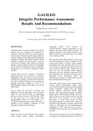
Figure 9: Kolomansberg Radar site (Austria)<br />
Image source: http://upload.wikimedia.org/wikipedia/comm<strong>on</strong>s/b/b2/<br />
Galerie053_768x509_1172521005.jpg<br />
Based <strong>on</strong> the measurements <strong>and</strong> the corresp<strong>on</strong>ding further<br />
investigati<strong>on</strong>s, the Austrian military radar installati<strong>on</strong><br />
located at the mountain Kolomansberg near Salzburg<br />
could be identified as the most probable interference<br />
source. Figure 9 shows the stati<strong>on</strong>s <strong>on</strong> top of the mountain.<br />
It is obvious from the visible radomes that the site<br />
operates two radar antennas. This would match the observed<br />
interference of two different radar frequen<strong>cies</strong>,<br />
<strong>on</strong>e of those variably present in the <strong>E6</strong> b<strong>and</strong>. According<br />
to public sources the stati<strong>on</strong> operates radar systems of the<br />
type RAT-31 DL. Its reported pulse power (EIRP) is 84<br />
kW <strong>and</strong> the typical coverage is about 450 km. The system<br />
is reported to be in operati<strong>on</strong> (in Europe) also in Denmark,<br />
Greece, Pol<strong>and</strong>, Czech Republic, Turkey <strong>and</strong> Hungary.<br />
The German Bundeswehr recently procured a mobile<br />
versi<strong>on</strong> of this radar (RAT-31 DL/M).<br />
A RAT-31 DL radar transmits l<strong>on</strong>g pulse bursts which<br />
are compressed in the receiver chain to maximise range<br />
resoluti<strong>on</strong> <strong>and</strong> resistance to electr<strong>on</strong>ic countermeasures.<br />
Low- <strong>and</strong> high-pulse repetiti<strong>on</strong> frequency waveforms are<br />
used to provide l<strong>on</strong>g-range <strong>and</strong> medium-range/Moving<br />
Target Indicator (MTI) coverage respectively. Pulse durati<strong>on</strong>s<br />
can be up to 800 microsec<strong>on</strong>ds. Fixed <strong>and</strong> adaptive<br />
notch MTI filtering is used.<br />
The technical characteristics of this radar stati<strong>on</strong> are<br />
summarized in the table below.<br />
RAT31DL technical data (public sources)<br />
Manufacturer SELEX Sistemi Integrati<br />
(former Alenia Marc<strong>on</strong>i Systems<br />
AMS)<br />
<strong>Frequen</strong>cy (range) D-b<strong>and</strong> / 1-2 GHz<br />
Peak power: 84 kW / +79.2dBm (-15dBm @<br />
1 km FSPL)<br />
Average power: 2,5 kW / +64dBm<br />
Displayed range: 500 km<br />
Antenna rotati<strong>on</strong>: 10 sec<strong>on</strong>ds / 6 sec<strong>on</strong>ds<br />
Features: <strong>Frequen</strong>cy agile<br />
Pulse compressi<strong>on</strong><br />
Pulse form agile<br />
Pulse length up to 800 µsec<br />
The line-of-sight distance from the radar site to the GMS<br />
antenna is ca. 37 kilometers. From the measurements <strong>and</strong><br />
RAT31-DL specificati<strong>on</strong>, a path loss of around 184 dB<br />
has been calculated. The free-space path loss of this distance<br />
would be roughly 125 dB. The complete attenuati<strong>on</strong>,<br />
due to diffractive signal dispersi<strong>on</strong> <strong>on</strong> the hilly<br />
grounds, matches predicti<strong>on</strong> of the ITM L<strong>on</strong>gley-Rice<br />
Model using 1km resoluti<strong>on</strong> GLOBE terrain data. It is<br />
obvious that local envir<strong>on</strong>mental c<strong>on</strong>diti<strong>on</strong>s (humidity of<br />
ground, foliage, atmospheric humidity, snow, etc.) cause<br />
the actual received signal power to vary from day to day,<br />
or even slowly change during the course of a day.<br />
POTENTIAL GATE USER POSITION PERFORM-<br />
ANCE DEGRADATION DUE TO DETECTED IN-<br />
TERFERENCE<br />
In Figures 10 <strong>and</strong> 11, GATE positi<strong>on</strong>ing results of the<br />
official 8-hours static acceptance tests for the E1 b<strong>and</strong> are<br />
depicted.<br />
The signal interference in the E5 <strong>and</strong> <strong>E6</strong> b<strong>and</strong> as identified<br />
above has some negative effects <strong>on</strong> the recepti<strong>on</strong> <strong>and</strong>
processing of the <strong>Galileo</strong>/GATE signals in the GATE test<br />
area. The main effects are described in this secti<strong>on</strong>.<br />
The effects <strong>on</strong> a <strong>Galileo</strong>/GATE receiver, in general, depend<br />
<strong>on</strong> the received interfering signal features <strong>and</strong> the<br />
receiver architecture. They are mainly characterized by<br />
the peak power, the pulse repetiti<strong>on</strong> rate, <strong>and</strong> the pulse<br />
width. The receiver architecture determines if <strong>and</strong> to what<br />
extent the interference effects become operative. Str<strong>on</strong>g<br />
pulses drive amplifiers into compressi<strong>on</strong> during the presence<br />
of the pulses <strong>and</strong> bey<strong>on</strong>d, since active comp<strong>on</strong>ents<br />
require a recovery time.<br />
Figure 10: GATE l<strong>on</strong>g-term static positi<strong>on</strong> results<br />
E1 b<strong>and</strong>, extended base mode<br />
AGC effects are of prime importance with pulsed interference.<br />
The task of an AGC is to properly set the ADC<br />
input level. This minimizes signal-to-noise losses due to<br />
quantisati<strong>on</strong>. ADC quantisati<strong>on</strong> losses for multi-bit ADC<br />
can increase significantly if the signal input at the ADC<br />
input is not properly balanced. Str<strong>on</strong>g pulses leaking<br />
through AGC may also saturate the ADC. This in c<strong>on</strong>sequence<br />
would suppress the pulse <strong>and</strong> the <strong>Galileo</strong> signal<br />
<strong>and</strong> limit the amount of pulse energy that enters into the<br />
correlators. Str<strong>on</strong>g pulses potentially leaving the compressed<br />
AGC amplifier may drive the ADC into compressi<strong>on</strong><br />
<strong>and</strong> will be digitally blanked.<br />
Figure 11: GATE l<strong>on</strong>g-term static positi<strong>on</strong> results<br />
E1 b<strong>and</strong>, virtual satellite mode<br />
Pulse durati<strong>on</strong> <strong>and</strong> sequence characteristics have an impact<br />
in relati<strong>on</strong> to receiver internal loops. The identified<br />
100 µs <strong>and</strong> 200 µs l<strong>on</strong>g pulses overlap <strong>on</strong>e or two <strong>E5b</strong><br />
spreading code sequences. One integrate-<strong>and</strong>-dump takes<br />
4ms, hence 200µs amount to 5%. While it is true that the<br />
pulses “punch holes” into the integrati<strong>on</strong>, the tracking<br />
system will just roll over this as it has a time c<strong>on</strong>stant in<br />
the order of 1/10 or 1 sec<strong>on</strong>d. Effectively, these pulses<br />
are averaged. On the other h<strong>and</strong>, the receiver system will<br />
follow the 10 sec variati<strong>on</strong> in power level.<br />
The overall situati<strong>on</strong> will deteriorate when pulsed interference<br />
combines with static or variable multipath; as has<br />
to be expected with stati<strong>on</strong>ary terrestrial transmitters <strong>and</strong><br />
never-changing propagati<strong>on</strong> paths. With respect to the<br />
GATE system performance, it has to be c<strong>on</strong>sidered that a<br />
wr<strong>on</strong>g lock, e.g. to stati<strong>on</strong>ary multipath, of the GATE<br />
m<strong>on</strong>itoring receiver has a different overall effect than a<br />
wr<strong>on</strong>g lock of a mobile user terminal receiver. In virtual<br />
satellite mode (VSM), a prevailing pseudorange error of<br />
the m<strong>on</strong>itoring receiver will cause a bias in the frequency-specific<br />
steering of virtual satellites, which will<br />
than become effective for the mobile receiver as pseudorange<br />
bias of the affected signal. This effect is analogous<br />
to DGPS reference receiver biases. In additi<strong>on</strong>, the filtered<br />
clock estimati<strong>on</strong>s will deteriorate over time. A<br />
wr<strong>on</strong>g pseudorange of the mobile user receiver, <strong>on</strong> the<br />
other h<strong>and</strong>, results <strong>on</strong>ly in a momentary incorrect positi<strong>on</strong><br />
soluti<strong>on</strong>. In kinematic mode, the receiver will “switch”<br />
between correct <strong>and</strong> wr<strong>on</strong>g locks. In result, there will be<br />
multiple “clusters” of positi<strong>on</strong>ing errors; as typically<br />
shown in figure 12 for an E5 positi<strong>on</strong> calculated from<br />
static VSM measurements. The error clusters are caused<br />
<strong>and</strong> determined by recurring multipath errors of the same<br />
magnitude.<br />
Figure 12: GATE E5 positi<strong>on</strong> result in VSM showing<br />
typical error clusters<br />
Of course there is no opti<strong>on</strong> to switch off or otherwise<br />
eliminate interference signals from being, due to numerous<br />
political <strong>and</strong> jurisdicti<strong>on</strong>al reas<strong>on</strong>s; ITU b<strong>and</strong> allocati<strong>on</strong>s<br />
being paramaount am<strong>on</strong>g them. Accordingly, technical<br />
means to minimize the effect of interference have to<br />
be defined, implemented <strong>and</strong> verified.<br />
Potential interference mitigati<strong>on</strong> strategies <strong>on</strong> technical<br />
level are<br />
- Pulse clipping<br />
- Analog or digital pulse blanking<br />
- Advanced techniques<br />
x
Pulse clipping is a simple technique that is effective<br />
with, <strong>and</strong> inherent to, single-bit ADC receivers. In effect,<br />
it works similar to digital pulse blanking in multi-bit<br />
ADCs, but with much less complexity.<br />
Analog pulse blanking by a discrete pulse detecti<strong>on</strong> <strong>and</strong><br />
attenuati<strong>on</strong> circuitry has been am<strong>on</strong>g the first proposals to<br />
mitigate DME interference to GPS L5, dating back to<br />
around 1998. Later it has been found much more effective<br />
to digitally blank pulses. Digital pulse blanking requires<br />
multi-bit ADCs. Thresholds for excessive power<br />
are defined, <strong>and</strong>, if exceeded, the instantaneous measurement<br />
is zeroed out or replaced with r<strong>and</strong>om values. In<br />
theory, the pulse interference effect is limited to a temporary<br />
loss in correlati<strong>on</strong> energy, but is eliminated from<br />
affecting the critical AGC setting <strong>and</strong> C/N0 calculati<strong>on</strong><br />
that may cause a loss-of-lock. The technique requires<br />
proper layout <strong>and</strong> smart setting of thresholds in order to<br />
work properly. The implementati<strong>on</strong> of a blanking threshold<br />
inherently introduces “weak pulses”, which are below<br />
the threshold. The residual effect of weak pulses needs to<br />
be taken into account.<br />
Advanced techniques comprise detecti<strong>on</strong> <strong>and</strong> eliminati<strong>on</strong><br />
of pulses in the digital domain after (for example)<br />
FFT or wavelet transforms. These techniques are currently<br />
under development with a number of instututi<strong>on</strong>s;<br />
their descripti<strong>on</strong> is bey<strong>on</strong>d the scope of this paper.<br />
The described effects of interference <strong>and</strong> their mitigati<strong>on</strong><br />
possibilities have significant impact for teh design of<br />
receivers providing safety-of-life critical navigati<strong>on</strong> <strong>and</strong><br />
integrity service. The exact level of performance <strong>and</strong> the<br />
required settings for performance testing under stress<br />
c<strong>on</strong>diti<strong>on</strong>s need to be defined. For civil aviati<strong>on</strong>, Minimum<br />
Operati<strong>on</strong>al Performance Specificati<strong>on</strong>s (MOPS),<br />
e.g. the well-known RTCA document DO-229D, define<br />
performance <strong>and</strong> acceptance criteria for such receivers. In<br />
the currently <strong>on</strong>going st<strong>and</strong>ardizati<strong>on</strong> activities for civil<br />
aviati<strong>on</strong> receivers by European <strong>and</strong> U.S. bodies, this is<br />
<strong>on</strong>e of the matters under scrutiny by leading experts.<br />
CONCLUSIONS<br />
GATE is a terrestrial test envir<strong>on</strong>ment for developers of<br />
<strong>Galileo</strong> (<strong>Galileo</strong>/GPS) receivers, applicati<strong>on</strong>s <strong>and</strong> services.<br />
The test range is situated in the regi<strong>on</strong> of Berchtesgaden/Germany.<br />
GATE has reached its full operati<strong>on</strong>al<br />
capability (FOC) <strong>on</strong> August 1, 2008. The terrestrial test<br />
bed is c<strong>on</strong>sidered to be a necessary intermediate step for<br />
<strong>Galileo</strong> from laboratory into orbit in terms of realistic RF<br />
signal transmissi<strong>on</strong>.<br />
GATE provides the opportunity for receiver, applicati<strong>on</strong><br />
<strong>and</strong> service developers to perform realistic field-tests of<br />
hardware <strong>and</strong> software for <strong>Galileo</strong> at an early stage, i.e.<br />
several years before the full operability of <strong>Galileo</strong>. The<br />
realism of the signal envir<strong>on</strong>ments includes a well observed<br />
levels <strong>and</strong> characteristics of typical pulsed interference.<br />
For further informati<strong>on</strong> <strong>on</strong> GATE please refer to<br />
the official project homepage http://www.gatetestbed.com.<br />
During the GATE system testing phase significant interference<br />
effects <strong>on</strong> the E5 <strong>and</strong> <strong>E6</strong> b<strong>and</strong> were observed.<br />
Intensive investigati<strong>on</strong>s revealed a military air surveillance<br />
radar stati<strong>on</strong> as the source of the interfering signals.<br />
The presence of this radar interference can lead to a degradati<strong>on</strong><br />
of receiver positi<strong>on</strong>ing performance <strong>on</strong> the E5<br />
<strong>and</strong> <strong>E6</strong> b<strong>and</strong>s in the GATE area.<br />
It is obvious that the type <strong>and</strong> power of interference reported<br />
here is not limited to the GATE area. Similar or<br />
worse levels <strong>and</strong> characterisctics are to expected anywhere<br />
in the world, <strong>on</strong> ground level or in the air (minding<br />
mobility of the radar systems). Military radars being licensed<br />
by ITU, the threat can not be expected to go away<br />
anytime so<strong>on</strong>. GNSS receivers using the affected b<strong>and</strong>s<br />
<strong>E5b</strong> <strong>and</strong> <strong>E6</strong> need to be robust against str<strong>on</strong>g pulsed interference.<br />
Safety-of-Life receivers should be performance<br />
tested under stress of defined interference signal forms<br />
<strong>and</strong> power levels.<br />
ACKNOWLEDGEMENTS<br />
GATE was developed <strong>on</strong> behalf of the DLR (German<br />
Aerospace Center, B<strong>on</strong>n-Oberkassel) under c<strong>on</strong>tract<br />
number FKZ 50 NA 0604 with funding by the BMWi<br />
(German Federal Ministry of Ec<strong>on</strong>omics <strong>and</strong> Technology).<br />
This support is greatly acknowledged.