4. crte power capacitors - IVD GmbH
4. crte power capacitors - IVD GmbH
4. crte power capacitors - IVD GmbH

You also want an ePaper? Increase the reach of your titles
YUMPU automatically turns print PDFs into web optimized ePapers that Google loves.
<strong>4.</strong> CRTE POWER CAPACITORS<br />
<strong>4.</strong>1 GENERAL DESCRIPTION<br />
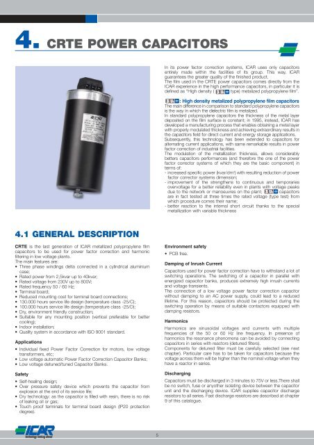
CRTE is the last generation of ICAR metallized polypropylene film<br />
<strong>capacitors</strong> to be used for <strong>power</strong> factor correction and harmonic<br />
filtering in low voltage plants.<br />
The main features are:<br />
• Three phase windings delta connected in a cylindrical aluminium<br />
case;<br />
• Rated <strong>power</strong> from 2,5kvar up to 40kvar;<br />
• Rated voltage from 230V up to 800V;<br />
• Rated frequency 50 / 60 Hz;<br />
• Terminal board;<br />
• Reduced mounting cost for terminal board connections;<br />
• 130.000 hours service life design (temperature class -25/C);<br />
• 100.000 hours service life design (temperature class -25/D);<br />
• Dry, environment friendly construction;<br />
• Suitable for any mounting position (vertical preferable for better<br />
cooling);<br />
• Indoor installation;<br />
• Quality system in accordance with ISO 9001 standard.<br />
Applications<br />
• Individual fixed Power Factor Correction for motors, low voltage<br />
transformers, etc;<br />
• Low voltage automatic Power Factor Correction Capacitor Banks;<br />
• Low voltage detuned/tuned Capacitor Banks.<br />
Safety<br />
• Self-healing design;<br />
• Over pressure safety device which prevents the capacitor from<br />
explosion at the end of its service life;<br />
• Dry technology: as the capacitor is filled with resin, there is no risk<br />
of leaking oil or gas;<br />
• Touch proof terminals for terminal board design (IP20 protection<br />
degree).<br />
5<br />
In its <strong>power</strong> factor correction systems, ICAR uses only <strong>capacitors</strong><br />
entirely made within the facilities of its group. This way, ICAR<br />
guarantees the greater quality of the finished product.<br />
The film used in the CRTE <strong>power</strong> <strong>capacitors</strong> comes directly from the<br />
ICAR experience in the high performance <strong>capacitors</strong>, in particular it is<br />
defined as “High density ( type) metalized polypropylene film”.<br />
: High density metalized polypropylene film <strong>capacitors</strong><br />
The main difference in comparison to standard polypropylene <strong>capacitors</strong><br />
is the way in which the dielectric film is metalized.<br />
In standard polypropylene <strong>capacitors</strong> the thickness of the metal layer<br />
deposited on the film surface is constant; in 1995, instead, ICAR has<br />
developed a manufacturing process that enables obtaining a metal layer<br />
with properly modulated thickness and achieving extraordinary results in<br />
the <strong>capacitors</strong> field for direct current and energy storage applications.<br />
Subsequently, this technology has been extended to <strong>capacitors</strong> for<br />
alternating current applications, with same remarkable results in <strong>power</strong><br />
factor correction of industrial facilities.<br />
The modulation of the metallization thickness, allows considerably<br />
betters <strong>capacitors</strong> performances (and therefore the one of the <strong>power</strong><br />
factor corrector systems of which they are the basic component) in<br />
terms of:<br />
- increased specific <strong>power</strong> (kvar/dm 3 ) with resulting reduction of <strong>power</strong><br />
factor corrector systems dimension;<br />
- improvement of the strengthens to continuous and temporaries<br />
overvoltage for a better reliability even in plants with voltage peaks<br />
due to the network or manoeuvres on the plant; <strong>capacitors</strong><br />
are in fact tested at three times the rated voltage (type test) from<br />
which procedure comes their name;<br />
- better reaction to the internal short circuit thanks to the special<br />
metallization with variable thickness<br />
Environment safety<br />
• PCB free.<br />
Damping of Inrush Current<br />
Capacitors used for <strong>power</strong> factor correction have to withstand a lot of<br />
switching operations. The switching of a capacitor in parallel with<br />
energized capacitor banks, produces extremely high inrush currents<br />
and voltage transients.<br />
The connection of a low voltage <strong>power</strong> factor correction capacitor<br />
without damping to an AC <strong>power</strong> supply, could lead to a reduced<br />
lifetime. For this reason, <strong>capacitors</strong> should be protected during the<br />
switching operation by means of suitable contactors equipped with<br />
damping resistors.<br />
Harmonics<br />
Harmonics are sinusoidal voltages and currents with multiple<br />
frequencies of the 50 or 60 Hz line frequency. In presence of<br />
harmonics the resonance phenomena can be avoided by connecting<br />
<strong>capacitors</strong> in series with reactors (detuned filters).<br />
Components for detuned filter must be carefully selected (see next<br />
chapter). Particular care has to be taken for <strong>capacitors</strong> because the<br />
voltage across them will be higher than the nominal voltage when they<br />
have a reactor in series.<br />
Discharging<br />
Capacitors must be discharged in 3 minutes to 75V or less.There shall<br />
be no switch, fuse or anyother isolating device between the capacitor<br />
unit and the discharging device. ICAR supplies capacitor discharge<br />
resistors to all series. Fast discharge resistors are described at chapter<br />
9 of this catalogue.
<strong>4.</strong> CRTE POWER CAPACITORS<br />
<strong>4.</strong>2 TECHNICAL DATA SHEETS AND TABLES<br />
TECHNICAL CHARACTERISTICS<br />
• Dielectric polypropylene metallized film<br />
• Winding connection delta<br />
• Safety device Internal overpressure disconnector<br />
• Capacitance tolerance -5%, +10%<br />
• Rated Voltage 230V, 400V/415V, 450V, 525V, 690V, 750V, 800V<br />
• Rated Frequency 50 Hz<br />
• Over voltages According to IEC<br />
• Un + 10% (up to 8 hours daily)<br />
• Un + 15% (up to 30 minutes daily)<br />
• Un + 20% (up to 5 minutes daily)<br />
• Un + 30% (up to 1 minute daily)<br />
• Over current 2 In (including harmonics)<br />
• Maximum inrush current 200 In<br />
• Insulation level 3 / 15 kV<br />
• Voltage test between terminals 2,15 Un, 50Hz, 10 seconds (routine test)<br />
• Voltage test between terminals 3,00 Un, 50Hz, 60 seconds (type test)<br />
Vn = 230V - 50Hz - Fi = 50Hz<br />
Q C In D H<br />
ORDER CODE MODEL POWER Capacity Current Diameter Heigh Weight Pcs/box<br />
(KVar) (µF) (A) (mm) (mm) (Kg)<br />
6<br />
Box Discharge<br />
dimensions resistor<br />
CRT233100156V00 CRT-56V-1-230 ** 1 3 x 20 3 x 2,5 55 165 0,5 30 370x370x245 Internal<br />
CRT233150156V00 CRT-56V-1,5-230 ** 1,5 3 x 30,1 3 x 3,8 55 165 0,5 30 370x370x245 Internal<br />
CRT233200166V00 CRT-66V-2-230 ** 2 3 x 40,1 3 x 5 65 205 0,7 6 370x370x106 Internal<br />
CRT233250166V00 CRT-66V-2,5-230 ** 2,5 3 x 50,1 3 x 6,3 65 205 0,7 6 370x370x106 Internal<br />
CRE501233M50322 CRTE08520805023 5 3 x 100 3 x 12,6 85 208 1,6 4 370x370x106 External<br />
CRE751233M50323 CRTE10020807523 7,5 3 x 150 3 x 18,9 100 208 2 3 370x370x106 External<br />
CRE102233M50315 CRTE10020810023 10 3 x 200 3 x 25,2 100 208 2 3 370x370x106 External<br />
CRE1D2233M50324 CRTE11620812523 12,5 3 x 250 3 x 31,5 116 208 2,6 3 370x370x125 External<br />
CRE152233M50325 CRTE13620815023 15 3 x 300 3 x 37,6 136 208 3,2 2 370x370x161 External<br />
Vn = 400V (415V) - 50Hz<br />
• Voltage test terminals/case 3000V, 50Hz, 10 seconds,<br />
• Voltage test terminals/case 6000V, 50Hz, 10 seconds (650V / 750V / 800V)<br />
• Dielectric losses < 0.2 W/kvar<br />
• Temperature class -25/D<br />
• Cooling Natural air of forced ventilation<br />
• Permissible humidity 95%<br />
• Service life 130.000 operating hours (temperature class -25/C)<br />
• Service life 100.000 operating hours (temperature class -25/D)<br />
• Altitude above sea level 2000 m<br />
• Impregnation resin filled, PCB free<br />
• Terminals Terminal board<br />
• Fixing and Ground Threaded M12 stud on case bottom<br />
• Mounting position vertical preferable for better cooling<br />
• Protection degree IP20<br />
• Installation Indoor<br />
• Discharge resistors Included<br />
• Discharge time < 3 minutes to 75V or less<br />
Applicable standards IEC 60831-1/2<br />
Q C In D H<br />
ORDER CODE MODEL POWER Capacity Current Diameter Heigh Weight Pcs/box<br />
(KVar) (µF) (A) (mm) (mm) (Kg)<br />
Box Discharge<br />
dimensions resistor<br />
CRT403100156V00 CRT-56V-1-400 ** 1 3 x 6,6 3 x 1,4 55 165 0,5 30 370x370x245 Internal<br />
CRT403150156V00 CRT-56V-1,5-400 ** 1,5 3 x 9,9 3 x 2,2 55 165 0,5 30 370x370x245 Internal<br />
CRT403200156V00 CRT-56V-2-400 ** 2 3 x 13,3 3 x 2,9 55 165 0,5 30 370x370x245 Internal<br />
CRT403250156V00 CRT-56V-2,5-400 ** 2,5 3 x 16,6 3 x 3,6 55 165 0,5 30 370x370x245 Internal<br />
CRT403300166V00 CRT-66V-3-400 ** 3 3 x 19,9 3 x 4,3 65 205 0,7 6 370x370x106 Internal<br />
CRT403400166V00 CRT-66V-4-400 ** 4 3 x 26,5 3 x 5,8 65 205 0,7 6 370x370x106 Internal<br />
CRT403500166V00 CRT-66V-5-400 ** 5 3 x 33,2 3 x 7,2 65 205 0,7 6 370x370x106 Internal<br />
CRE501403M50028 CRTE07520805040 5 3 x 33,2 3 x 7,2 75 208 1,2 5 370x370x106 External<br />
CRE751403M50033 CRTE07520807540 7,5 3 x 49,7 3 x 10,8 75 208 1,2 5 370x370x106 External<br />
CRE102403M50053 CRTE08520810040 10 3 x 66,3 3 x 14,4 85 208 1,6 4 370x370x106 External<br />
CRE1D2403M50036 CRTE08520812540 12,5 3 x 82,9 3 x 18 85 208 1,6 4 370x370x106 External<br />
CRE152403M50054 CRTE10020815040 15 3 x 99,5 3 x 21,7 100 208 2 3 370x370x106 External<br />
CRE202403M50001 CRTE10020820040 20 3 x 132,6 3 x 28,9 100 208 2 3 370x370x106 External<br />
CRE252403M50002 CRTE11620825040 25 3 x 165,8 3 x 36,1 116 208 2,6 3 370x370x125 External<br />
CRE302403M50003 CRTE11620830040 30 3 x 198,9 3 x 43,3 116 208 2,6 3 370x370x125 External<br />
CRE402403M50108 CRTE13628340040 ** 40 3 x 265,4 3 x 57,7 136 283 3,8 2 370x370x125 External<br />
* File number E99479<br />
** Not UL approved<br />
*<br />
*<br />
*<br />
Vn = 450V - 50Hz<br />
ORDER CODE MODEL<br />
Q<br />
POWER<br />
(KVar)<br />
C<br />
Capacity<br />
(µF)<br />
In<br />
Current<br />
(A)<br />
D<br />
Diameter<br />
(mm)<br />
H<br />
Heigh<br />
(mm)<br />
Weight<br />
(Kg)<br />
Pcs/box<br />
Box<br />
dimensions<br />
Discharge<br />
resistor<br />
CRT453100156V00 CRT-56V-1-450 ** 1 3 x 5,2 3 x 1,3 55 165 0,5 30 370x370x245 Internal<br />
CRT453150156V00 CRT-56V-1,5-450 ** 1,5 3 x 7,9 3 x 1,9 55 165 0,5 30 370x370x245 Internal<br />
CRT453200156V00 CRT-56V-2-450 ** 2 3 x 10,5 3 x 2,6 55 165 0,5 30 370x370x245 Internal<br />
CRT453250156V00 CRT-56V-2,5-450 ** 2,5 3 x 13,1 3 x 3,2 55 165 0,5 30 370x370x245 Internal<br />
CRT453300166V00 CRT-66V-3-450 ** 3 3 x 15,7 3 x 3,8 65 205 0,7 6 370x370x106 Internal<br />
CRT453400166V00 CRT-66V-4-450 ** 4 3 x 21 3 x 5,1 65 205 0,7 6 370x370x106 Internal<br />
CRT453500166V00 CRT-66V-5-450 ** 5 3 x 26,2 3 x 6,4 65 205 0,7 6 370x370x106 Internal<br />
CRE501453M50015 CRTE07520805045 5 3 x 26,2 3 x 6,4 75 208 1,2 5 370x370x106 External<br />
CRE751453M50034 CRTE07520807545 7,5 3 x 39,3 3 x 9,6 75 208 1,2 5 370x370x106 External<br />
CRE102453M50055 CRTE08520810045 10 3 x 52,4 3 x 12,8 85 208 1,6 4 370x370x106 External<br />
CRE1D2453M50037 CRTE08520812545 12,5 3 x 65,5 3 x 16 85 208 1,6 4 370x370x106 External<br />
CRE152453M50056 CRTE10020815045 15 3 x 78,6 3 x 19,2 100 208 2 3 370x370x106 External<br />
CRE202453M50010 CRTE10020820045 20 3 x 104,8 3 x 25,7 100 208 2 3 370x370x106 External<br />
CRE252453M50004 CRTE11620825045 25 3 x 131 3 x 32,1 116 208 2,6 3 370x370x125 External<br />
CRE302453M50009 CRTE11620830045 30 3 x 157,2 3 x 38,5 116 208 2,6 3 370x370x125 External<br />
CRE402453M50162 CRTE13628340045 ** 40 3 x 209,7 3 x 51,3 136 283 3,8 2 370x370x161 External
<strong>4.</strong> CRTE POWER CAPACITORS<br />
Vn = 525V - 50Hz<br />
Q C In D H<br />
ORDER CODE MODEL POWER Capacity Current Diameter Heigh Weight Pcs/box<br />
(KVar) (µF) (A) (mm) (mm) (Kg)<br />
7<br />
Box Discharge<br />
dimensions resistor<br />
CRT523100156V00 CRT-56V-1-525 ** 1 3 x 3,8 3 x 1,1 55 165 0,5 30 370x370x245 Internal<br />
CRT523150156V00 CRT-56V-1,5-525 ** 1,5 3 x 5,8 3 x 1,6 55 165 0,5 30 370x370x245 Internal<br />
CRT523200156V00 CRT-56V-2-525 ** 2 3 x 7,7 3 x 2,2 55 165 0,5 30 370x370x245 Internal<br />
CRT523250156V00 CRT-56V-2,5-525 ** 2,5 3 x 9,6 3 x 2,7 55 165 0,5 30 370x370x245 Internal<br />
CRT523300166V00 CRT-66V-3-525 ** 3 3 x 11,5 3 x 3,3 65 205 0,7 6 370x370x106 Internal<br />
CRT523400166V00 CRT-66V-4-525 ** 4 3 x 15,4 3 x 4,4 65 205 0,7 6 370x370x106 Internal<br />
CRT523500166V00 CRT-66V-5-525 ** 5 3 x 19,2 3 x 5,5 65 205 0,7 6 370x370x106 Internal<br />
CRE501523M50016 CRTE07520805052 5 3 x 19,2 3 x 5,5 75 208 1,2 5 370x370x106 External<br />
CRE751523M50035 CRTE07520807552 7,5 3 x 28,9 3 x 8,2 75 208 1,2 5 370x370x106 External<br />
CRE102523M50057 CRTE08520810052 10 3 x 38,5 3 x 11 85 208 1,6 4 370x370x106 External<br />
CRE1D2523M50038 CRTE08520812552 12,5 3 x 48,1 3 x 13,7 85 208 1,6 4 370x370x106 External<br />
CRE152523M50058 CRTE10020815052 15 3 x 57,7 3 x 16,5 100 208 2 3 370x370x106 External<br />
CRE202523M50021 CRTE10020820052 20 3 x 77 3 x 22 100 208 2 3 370x370x106 External<br />
CRE252523M50022 CRTE11620825052 25 3 x 96,2 3 x 27,5 116 208 2,6 3 370x370x125 External<br />
CRE302523M50023 CRTE11620830052 30 3 x 115,5 3 x 33 116 208 2,6 3 370x370x125 External<br />
CRE402523M50079 CRTE13620840052 40 3 x 154 3 x 44 136 208 3,2 2 370x370x161 External<br />
Vn = 690V - 50Hz<br />
Q C In D H<br />
ORDER CODE MODEL POWER Capacity Current Diameter Heigh Weight Pcs/box<br />
(KVar) (µF) (A) (mm) (mm) (Kg)<br />
Box Discharge<br />
dimensions resistor<br />
CRE501693M50163 CRTE07520805069 5 3 x 11,1 3 x 4,2 75 208 1,2 5 370x370x106 External<br />
CRE751693M50164 CRTE08520807569 7,5 3 x 16,7 3 x 6,3 85 208 1,6 4 370x370x106 External<br />
CRE102693M50165 CRTE10020810069 10 3 x 22,3 3 x 8,4 100 208 2 3 370x370x106 External<br />
CRE1D2693M50166 CRTE10020812569 12,5 3 x 27,9 3 x 10,5 100 208 2 3 370x370x106 External<br />
CRE152693M50167 CRTE11620815069 15 3 x 33,4 3 x 12,5 116 208 2,6 3 370x370x125 External<br />
CRE202693M50168 CRTE11620820069 20 3 x 44,6 3 x 16,7 116 208 2,6 3 370x370x125 External<br />
CRE252693M50111 CRTE13620825069 25 3 x 55,7 3 x 20,9 136 208 3,2 2 370x370x161 External<br />
CRE302693M50006 CRTE11628330069 30 3 x 66,9 3 x 25,1 116 283 3,2 3 370x370x125 External<br />
CRE402693M50169 CRTE13628340069 40 3 x 89,2 3 x 33,5 136 283 3,8 2 370x370x161 External<br />
Vn = 750V - 50Hz<br />
Q C In D H<br />
ORDER CODE MODEL POWER Capacity Current Diameter Heigh Weight Pcs/box<br />
(KVar) (µF) (A) (mm) (mm) (Kg)<br />
Box Discharge<br />
dimensions resistor<br />
CRE501753M50170 CRTE07520805075 5 3 x 9,4 3 x 3,8 75 208 1,2 5 370x370x106 External<br />
CRE751753M50171 CRTE08520807575 7,5 3 x 14,1 3 x 5,8 85 208 1,6 4 370x370x106 External<br />
CRE102753M50172 CRTE10020810075 10 3 x 18,9 3 x 7,7 100 208 2 3 370x370x106 External<br />
CRE1D2753M50173 CRTE11620812575 12,5 3 x 23,6 3 x 9,6 116 208 2,6 3 370x370x125 External<br />
CRE152753M50174 CRTE11620815075 15 3 x 28,3 3 x 11,5 116 208 2,6 3 370x370x125 External<br />
CRE202753M50175 CRTE13620820075 20 3 x 37,7 3 x 15,4 136 208 3,2 2 370x370x161 External<br />
CRE252753M50042 CRTE11628325075 25 3 x 47,2 3 x 19,2 116 283 3,2 3 370x370x125 External<br />
CRE302753M50176 CRTE13628330075 30 3 x 56,6 3 x 23,1 136 283 3,8 2 370x370x161 External<br />
CRE352753M50177 CRTE13628335075 35 3 x 66 3 x 26,9 136 283 3,8 2 370x370x161 External<br />
Vn = 800V - 50Hz<br />
*<br />
Q C In D H<br />
ORDER CODE MODEL POWER Capacity Current Diameter Heigh Weight Pcs/box<br />
(KVar) (µF) (A) (mm) (mm) (Kg)<br />
Box Discharge<br />
dimensions resistor<br />
CRE501803M50178 CRTE08520805080 5 3 x 8,3 3 x 3,6 85 208 1,6 4 370x370x106 External<br />
CRE751803M50044 CRTE10020807580 7,5 3 x 12,4 3 x 5,4 100 208 2 3 370x370x106 External<br />
CRE102803M50179 CRTE10020810080 10 3 x 16,6 3 x 7,2 100 208 2,6 3 370x370x106 External<br />
CRE1D2803M50180 CRTE11620812580 12,5 3 x 20,7 3 x 9 116 208 2,6 3 370x370x125 External<br />
CRE152803M50181 CRTE13620815080 15 3 x 24,9 3 x 10,8 136 208 3,2 2 370x370x161 External<br />
CRE202803M50182 CRTE13620820080 20 3 x 33,2 3 x 14,4 136 208 3,2 2 370x370x161 External<br />
CRE252803M50183 CRTE13628325080 25 3 x 41,5 3 x 18 136 283 3,8 2 370x370x161 External<br />
CRE302803M50184 CRTE13628330080 30 3 x 49,8 3 x 21,6 136 283 3,8 2 370x370x161 External<br />
* File number E99479<br />
** Not UL approved
<strong>4.</strong> CRTE POWER CAPACITORS<br />
<strong>4.</strong>3 TECHNICAL DATA SHEETS AND TABLES<br />
TECHNICAL CHARACTERISTICS<br />
• Dielectric polypropylene metallized film<br />
• Winding connection delta<br />
• Safety device Internal overpressure disconnector<br />
• Capacitance tolerance -5%, +10%<br />
• Rated Voltage 230V, 380V, 480V<br />
• Rated Frequency 60 Hz<br />
• Over voltages According to IEC<br />
• Un + 10% (up to 8 hours daily)<br />
• Un + 15% (up to 30 minutes daily)<br />
• Un + 20% (up to 5 minutes daily)<br />
• Un + 30% (up to 1 minute daily)<br />
• Over current 2 In (including harmonics)<br />
• Maximum inrush current 200 In<br />
• Insulation level 3 / 15 kV<br />
• Voltage test between terminals 2,15 Un, 50Hz, 10 seconds (routine test)<br />
• Voltage test between terminals 3,00 Un, 50Hz, 60 seconds (type test)<br />
Vn = 230V - 60Hz<br />
Q C In D H<br />
ORDER CODE MODEL POWER Capacity Current Diameter Heigh Weight Pcs/box<br />
(KVar) (µF) (A) (mm) (mm) (Kg)<br />
Vn = 380V - 60Hz<br />
Q C In D H<br />
ORDER CODE MODEL POWER Capacity Current Diameter Heigh Weight Pcs/box<br />
(KVar) (µF) (A) (mm) (mm) (Kg)<br />
8<br />
Box Discharge<br />
dimensions resistor<br />
CRT233120156V60 CRT-56V-1,2-230/60 ** 1,2 3 x 20 3 x 3 55 165 0,5 30 370x370x245 Internal<br />
CRT233180156V60 CRT-56V-1,8-230/60 ** 1,8 3 x 30,1 3 x 4,5 55 165 0,5 30 370x370x245 Internal<br />
CRT133240166V60 CRT-66V-2,4-230/60 ** 2,4 3 x 40,1 3 x 6 65 205 0,7 6 370x370x106 Internal<br />
CRT233300166V60 CRT-66V-3-230/60 ** 3 3 x 50,1 3 x 7,5 65 205 0,7 6 370x370x106 Internal<br />
CRE601233M60059 CRTE08520806023/60 6 3 x 100 3 x 15 85 208 1,6 4 370x370x106 External<br />
CRE901233M60060 CRTE10020809023/60 9 3 x 150 3 x 22,6 100 208 2 3 370x370x106 External<br />
CRE122233M60031 CRTE10020812023/60 12 3 x 200 3 x 30 100 208 2 3 370x370x106 External<br />
CRE152233M60032 CRTE11620815023/60 15 3 x 250 3 x 37,6 116 208 2,6 3 370x370x125 External<br />
CRE182233M60186 CRTE13620818023/60 18 3 x 300 3 x 45,2 136 208 3,2 2 370x370x161 External<br />
Box Discharge<br />
dimensions resistor<br />
CRT383110156V60 CRT-56V-1,1-380/60 ** 1,1 3 x 6,6 3 x 1,7 55 165 0,5 30 370x370x245 Internal<br />
CRT383160156V60 CRT-56V-1,6-380/60 ** 1,6 3 x 9,9 3 x 2,4 55 165 0,5 30 370x370x245 Internal<br />
CRT383220156V60 CRT-56V-2,2-380/60 ** 2,2 3 x 13,3 3 x 3,3 55 165 0,5 30 370x370x245 Internal<br />
CRT383270156V60 CRT-56V-2,7-380/60 ** 2,7 3 x 16,6 3 x 4,1 55 165 0,5 30 370x370x245 Internal<br />
CRT383320166V60 CRT-66V-3,2-380/60 ** 3,2 3 x 19,9 3 x 4,9 65 205 0,7 6 370x370x106 Internal<br />
CRT383430166V60 CRT-66V-4,3-380/60 ** 4,3 3 x 26,5 3 x 6,5 65 205 0,7 6 370x370x106 Internal<br />
CRT383540166V60 CRT-66V-5,4-380/60 ** 5,4 3 x 33,2 3 x 8,2 65 205 0,7 6 370x370x106 Internal<br />
CRE541383M60326 CRTE07520805438/60 5,4 3 x 33,2 3 x 8,2 75 208 1,2 5 370x370x106 External<br />
CRE811383M60327 CRTE07520808138/60 8,1 3 x 49,7 3 x 12,3 75 208 1,2 5 370x370x106 External<br />
CRE1E2383M60328 CRTE08520810838/60 10,8 3 x 66,3 3 x 16,4 85 208 1,6 4 370x370x106 External<br />
CRE1L2383M60329 CRTE08520813538/60 13,5 3 x 82,9 3 x 20,5 85 208 1,6 4 370x370x106 External<br />
CRE1Q2383M60330 CRTE10020816238/60 16,2 3 x 99,5 3 x 24,6 100 208 2 3 370x370x106 External<br />
CRE2F2383M60331 CRTE10020821738/60 21,7 3 x 132,6 3 x 33 100 208 2 3 370x370x106 External<br />
CRE2G2383M60193 CRTE11620827138/60 27,1 3 x 165,8 3 x 41,2 116 208 2,6 3 370x370x125 External<br />
Vn = 480V - 60Hz<br />
*<br />
*<br />
*<br />
• Voltage test terminals/case 3000V, 50Hz, 10 seconds<br />
• Dielectric losses < 0.2 W/kvar<br />
• Temperature class -25/D<br />
• Cooling Natural air of forced ventilation<br />
• Permissible humidity 95%<br />
• Service life 130.000 operating hours (temperature class -25/C)<br />
• Service life 100.000 operating hours (temperature class -25/D)<br />
• Altitude above sea level 2000 m<br />
• Impregnation resin filled, PCB free<br />
• Terminals Terminal board<br />
• Fixing and Ground Threaded M12 stud on case bottom<br />
• Mounting position vertical preferable for better cooling<br />
• Protection degree IP20<br />
• Installation Indoor<br />
• Discharge resistors Included<br />
• Discharge time < 3 minutes to 75V or less<br />
Applicable standards IEC 60831-1/2<br />
Q C In D H<br />
ORDER CODE MODEL POWER Capacity Current Diameter Heigh Weight Pcs/box<br />
(KVar) (µF) (A) (mm) (mm) (Kg)<br />
Box Discharge<br />
dimensions resistor<br />
CRT523100156V00 CRT-56V-1-480/60 ** 1 3 x 3,8 3 x 1,2 55 165 0,5 30 370x370x245 Internal<br />
CRT523150156V00 CRT-56V-1,5-480/60 ** 1,5 3 x 5,8 3 x 1,8 55 165 0,5 30 370x370x245 Internal<br />
CRT523200156V00 CRT-56V-2-480/60 ** 2 3 x 7,7 3 x 2,4 55 165 0,5 30 370x370x245 Internal<br />
CRT523250156V00 CRT-56V-2,5-480/60 ** 2,5 3 x 9,6 3 x 3 55 165 0,5 30 370x370x245 Internal<br />
CRT523300166V00 CRT-66V-3-480/60 ** 3 3 x 11,5 3 x 3,6 65 205 0,7 6 370x370x106 Internal<br />
CRT523400166V00 CRT-66V-4-480/60 ** 4 3 x 15,4 3 x 4,8 65 205 0,7 6 370x370x106 Internal<br />
CRT523500166V00 CRT-66V-5-480/60 ** 5 3 x 19,2 3 x 6 65 205 0,7 6 370x370x106 Internal<br />
CRE501483M60085 CRTE07520805048/60 5 3 x 19,2 3 x 6 75 208 1,2 5 370x370x106 External<br />
CRE751483M60086 CRTE07520807548/60 7,5 3 x 28,9 3 x 9 75 208 1,2 5 370x370x106 External<br />
CRE102483M60087 CRTE08520810048/60 10 3 x 38,5 3 x 12 85 208 1,6 4 370x370x106 External<br />
CRE1D2483M60088 CRTE08520812548/60 12,5 3 x 48,1 3 x 15 85 208 1,6 4 370x370x106 External<br />
CRE152483M60089 CRTE10020815048/60 15 3 x 57,7 3 x 18 100 208 2 3 370x370x106 External<br />
CRE202483M60090 CRTE10020820048/60 20 3 x 77 3 x 24,1 100 208 2 3 370x370x106 External<br />
CRE252483M60091 CRTE11620825048/60 25 3 x 96,2 3 x 30,1 116 208 2,6 3 370x370x125 External<br />
CRE302483M60092 CRTE11620830048/60 30 3 x 115,5 3 x 36,1 116 208 2,6 3 370x370x125 External<br />
CRE402483M60198<br />
* File number E99479<br />
** Not UL approved<br />
CRTE13620840048/60 40 3 x 154 3 x 48,1 136 208 3,2 2 370x370x161 External
<strong>4.</strong> CRTE POWER CAPACITORS<br />
<strong>4.</strong>4 DIMENSIONS AND CONNECTING CABLE CROSS SECTION<br />
Max case elangation in case of over pressure disconnetor activated<br />
< 12,7 mm.<br />
Below table is a guidelines for operation in normal conditions at ambient<br />
temperature up to 40°C (or 55°C capacitor sorroundig air).<br />
Various parameter such us harmonics, temperature inside the cabinet, cable<br />
length have to be considered for proper selection.<br />
<strong>4.</strong>5 LIMITS FOR PARALLEL OF CRTE CAPACITORS<br />
Unit 2 Unit 1<br />
Aluminium finishing: black painted for diameter ØD 100, ØD 116, ØD 136.<br />
naked for diameter ØD 75, ØD 85<br />
Terminals : 25mm 2 for ØD 85, ØD 100, ØD 116, ØD 136<br />
16mm 2 for ØD 75<br />
Maximum continuative<br />
terminal current: 25mm 2 60Arms<br />
16mm 2 35Arms<br />
Degree of protection: IP20<br />
Creepage 19 mm<br />
Clearance 19 mm<br />
Humidity class: F. Max relative humidity 75% annual on average,<br />
95% 30 days per year, condensation not permitted.<br />
ØD1 L1 L2 HT a<br />
ØD 75.................. 81 39,0 45,0 32±1 13<br />
ØD 85.................. 91 43,5 49,0 35±1 14<br />
ØD 100.................. 106 43,5 49,0 35Max 14<br />
ØD 116.................. 122 43,5 49,0 35Max 14<br />
ØD 136.................. 142 43,5 49,0 35Max 14<br />
Rated voltage 415V,<br />
50 Hz<br />
9<br />
RATED POWER Qn [kvar] In [A] CROSS SECTION mm 2 CU<br />
2.5 3.5 2.5<br />
5 7 2.5<br />
7.5 10.5 2.5<br />
10 13.9 4<br />
12.5 17.4 4<br />
15 20.9 6<br />
20 27.8 10<br />
25 3<strong>4.</strong>8 16<br />
40 55.6 25<br />
phase 1<br />
phase 2<br />
phase 3<br />
The maximum number of parallel connected units should not have a total output higher than 40kvar. The cross section of cables in the<br />
Unit 1 (phase 1, 2, 3) have to be selected considering the total amount of the Unit 1 and Unit 2 output.<br />
Leave enough space to allow longitudinal expansion of the can for proper operation of the internal over pressure safety device (15 mm).<br />
A minimum space of 20 mm between <strong>capacitors</strong> is necessary to ensure proper cooling.
<strong>4.</strong> CRTE POWER CAPACITORS<br />
<strong>4.</strong>6 INSTALLATION AND MAINTENANCE<br />
Handling and Storage<br />
Capacitors shall have to be handled and stored with care in order to<br />
avoid any mechanical damage during transportation. Protection<br />
against environmental influences shall also be taken.<br />
Installation<br />
Capacitors are suitable for indoor installation and for any mounting<br />
position. Vertical is preferable for better coolig.<br />
Capacitors must be installed in such a way that the specified limit<br />
temperature is not overcome.<br />
Not being in compliance with the above instructions will result as a<br />
reduction of the expected service life.<br />
Installation of <strong>capacitors</strong> shall have to be performed in such a way that<br />
any dangerous resonance phenomena due to harmonics is avoided.<br />
Automatic <strong>power</strong> factor correction banks<br />
The switching of a capacitor bank in parallel with energized<br />
capacitor(s), produces extremely high inrush currents and voltage<br />
transients. For this reason, it is extremely important to wait for the unit<br />
discharge before a new switching.<br />
Assembly<br />
Capacitors shall have to be assembled by means of the threaded M12<br />
bottom stud. The maximum applicable tightening torque is 10Nm.<br />
<strong>4.</strong>7 SAFETY INSTRUCTIONS<br />
DO NOT MISAPPLY CAPACITORS FOR POWER FACTOR<br />
CORRECTION APPLICATIONS.<br />
Capacitors according to the Standards, are equipped with a suitable<br />
discharge device such as discharge resistors, permanently connected.<br />
They are able to reduce the residual voltage across capacitor terminal<br />
to less than 75 V within 3 minutes or better.<br />
DO NOT TOUCH ANY CAPACITOR TERMINAL IF NOT SHORT<br />
CIRCUITED AND EARTHED IN ADVANCE.<br />
To prevent damage to people and goods due to improper usage<br />
and/or application of <strong>capacitors</strong>, the “RECOMMENDATION FOR THE<br />
SAFE USE OF STATIC CAPACITORS, BANKS AND EQUIPMENT FOR<br />
POWERFACTOR CORRECTION” published by ANIE shall have to be<br />
strictly respected.<br />
ICAR is not responsible for any kind of possible damages occurred to<br />
people or things, derived from the improper installation and application<br />
of Power Factor Correction <strong>capacitors</strong>.<br />
Most common misapplication forms<br />
• Current, voltage, harmonics and frequency above specification;<br />
• Working or storage temperature beyond the specified limits;<br />
• Unusual service conditions as mechanical shock and vibrations,<br />
corrosive or abrasive conductive parts in cooling air, oil or water<br />
vapour or corrosive substances, explosive gas or dust, radioactivity,<br />
excessive and fast variations of ambient conditions, service areas<br />
higher than 2000 m above sea level...<br />
In case of doubt in choice or in performances of the <strong>capacitors</strong> ICAR<br />
technical service MUST be contacted.<br />
10<br />
The catalogue specifies the recommended cross section of the<br />
supplying cables. The suggested tightening torque is 3Nm. With<br />
terminals screw design two antagonist spanners shall be used.<br />
In order to ensure a proper operation of the internal overpressure<br />
safety device, an extra minimum 15mm clearance distance between<br />
the upper part of <strong>capacitors</strong> and assembly enclosures shall have to be<br />
provided.<br />
Capacitors shall be placed in such a way that there is an adequate<br />
dissipation by convection and radiation of the heat produced by the<br />
capacitor losses. The ventilation of the operating cabinet and the<br />
arrangement of the capacitor units shall provide good air circulation<br />
around each unit. A minimum 20mm distance between the units has<br />
to be maintained.<br />
Maintenence<br />
Periodical checks and inspections are required to ensure reliable<br />
operation of <strong>capacitors</strong>. Monitoring and recording of the electrical<br />
service parameters are also recommended to become acquainted<br />
with progressive <strong>capacitors</strong> stress conditions.<br />
Protections<br />
Capacitors shall have to be protected against inrush peak currents<br />
during switching operations of automatic banks by means of suitable<br />
contactors equipped with pre-making resistors.<br />
Personal Safety<br />
Electrical or mechanical misapplications of CRTE <strong>capacitors</strong> may<br />
become hazardous. Personal injury or property damage may result<br />
from disruption of the capacitor and consequent expulsion of melted<br />
material.<br />
Before using the <strong>capacitors</strong> in any application, please read carefully<br />
the technical information contained in this catalogue.<br />
The energy stored in a capacitor may become lethal. The capacitor<br />
should be short circuited and earthed before handling to prevent any<br />
chance of shock.<br />
Special attention must be taken to make sure the <strong>capacitors</strong> are<br />
correctly used for each application and that warnings and instructions<br />
are strictly followed.<br />
Capacitors are made with polypropylene that is a flammable material.<br />
The risk of fire cannot be totally eliminated; therefore suitable<br />
precautions shall be taken. Reliability data quoted by ICAR should be<br />
considered as statistical i.e. based on a number of components, and<br />
does not guarantee properties or performance in the legal sense. ICAR<br />
liability is limited to the replacement of defective components.<br />
This applies in particular to consequential damage caused by<br />
component failure.
<strong>4.</strong> CRTE POWER CAPACITORS<br />
<strong>4.</strong>8 CERTIFICATES AND APPROVALS<br />
11