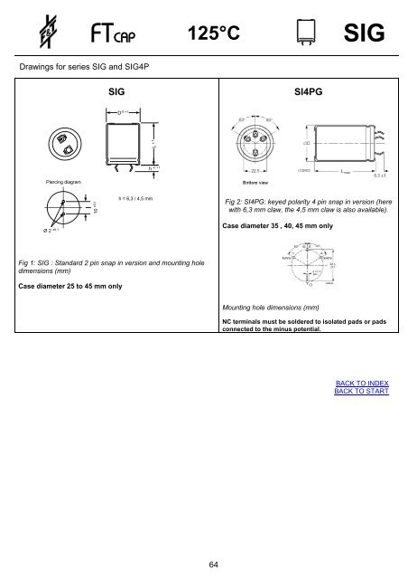
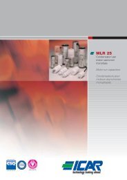
Drawings for series SIG and SIG4P Piercing diagram Ø 2 ±0,1 FTCAP 125°C SIG 10 ±0,1 SIG Fig 1: SIG : Standard 2 pin snap in version and mounting hole dimensions (mm) Case diameter 25 to 45 mm only D-0 +1 h = 6,3 / 4,5 mm L ± 1 -0 +1 h 64 SI4PG Fig 2: SI4PG: keyed polarity 4 pin snap in version (here with 6,3 mm claw, the 4,5 mm claw is also available). Case diameter 35 , 40, 45 mm only Mounting hole dimensions (mm) NC terminals must be soldered to isolated pads or pads connected to the minus potential. BACK TO INDEX BACK TO START
FTCAP 125°C SIG Electrical data and ordering codes series SIG Rated voltage UR [V] 16 25 Rated cap. CR [µF] Case size D x L [mm] Typ. ESR Ripple current IR~ 100 Hz, 100 Hz, 125°C [A] 20°C [mΩ] Order code 2 pins: SIG… 4 pins: SI4PG… 10000 25x30 40 2,7 10301625030 15000 30x30 27 3,6 15301630030 18000 25x50 22 4,3 18301625050 18000 35x30 22 4,3 18301635030 27000 30x50 15 5,8 27301630050 39000 30x70 10 7,9 39301630070 39000 35x50 10 7,6 39301635050 47000 40x50 8 8,8 47301640050 82000 35x80 5 14,6 82301635080 0 82000 40x80 5 13,9 82301640080 100000 45x80 4 15,4 10401645080 120000 40x100 4 16,9 12401640100 130000 45x100 4 17,5 13401645100 6800 25x30 47 2,5 68202525030 10000 30x30 32 3,3 10302530030 15000 25x50 21 4,4 15302525050 15000 35x30 21 4,4 15302535030 18000 30x50 18 5,3 18302530050 27000 30x70 12 7,4 27302530070 27000 35x50 12 7,1 27302535050 39000 40x50 8 9,0 39302540050 47000 35x80 7 11,3 47302535080 56000 45x80 6 12,9 56302545080 68000 40x80 5 14,2 68302540080 68000 40x100 5 15,5 68302540100 100000 45x100 3 18,8 10402545100 65 Rated voltage UR [V] 40 63 Rated cap. CR [µF] Case size D x L [mm] Typ. ESR Ripple current IR~ 100 Hz, 100 Hz, 125°C [A] 20°C [mΩ] Order code 2 pins: SIG… 4 pins: SI4PG… 2700 25x30 71 2,0 27204025030 3900 30x30 49 2,7 39204030030 4700 25x50 41 3,2 47204025050 6800 35x30 28 4,0 68204035030 8200 30x50 23 4,7 82204030050 10000 35x50 19 5,7 10304035050 12000 30x70 16 6,5 12304030070 15000 40x50 13 7,4 15304040050 18000 35x80 11 9,3 18304035080 22000 40x80 9 10,8 22304040080 27000 45x80 7 13,2 27304045080 27000 40x100 7 13,1 27304040100 39000 45x100 5 16,8 39304045100 1800 25x30 80 1,9 18206325030 2700 30x30 53 2,6 27206330030 3900 25x50 37 3,4 39206325050 3900 35x30 37 3,5 39206335030 5600 30x50 26 4,5 56206330050 6800 35x50 21 5,5 68206335050 8200 30x70 17 6,2 82206330070 10000 40x50 14 7,0 10306340050 12000 35x80 12 8,7 12306335080 18000 40x80 8 11,2 18306340080 22000 45x80 7 13,8 22306345080 22000 40x100 7 13,6 22306340100 27000 45x100 5 16,2 27306345100 BACK TO INDEX BACK TO START
- Page 1:
www.ftcap.de FTCAP Electroyltic Cap
- Page 4 and 5:
Aluminium Electrolytic Capacitors F
- Page 6 and 7:
CA CK Aluminium Electrolytic Capaci
- Page 8 and 9:
3.8 ESR Aluminium Electrolytic Capa
- Page 10 and 11:
6. Quality 6.1 Certification FTCAP
- Page 12 and 13:
FTCAP 85°C A Electrical data and o
- Page 14 and 15:
3 2,5 2 1,5 1 0,5 FTCAP 85°C A Use
- Page 16 and 17: FTCAP 105°C AH Electrical data and
- Page 18 and 19: 3 2,5 2 1,5 1 0,5 FTCAP 105°C AH U
- Page 20 and 21: FTCAP 125°C AG Electrical data and
- Page 22 and 23: FTCAP 85°C ATBI Electrical data an
- Page 24 and 25: FTCAP 85°C ATBIG Electrical data a
- Page 26 and 27: Drawings for series GMA and GMB FTC
- Page 28 and 29: Rated voltage UR [V] 63 80 100 Rate
- Page 30 and 31: Rated voltage UR [V] 500 Rated cap.
- Page 32 and 33: Drawings for series GMXA and GMXB F
- Page 34 and 35: Rated voltage UR [V] 63 80 100 Rate
- Page 36 and 37: 3 2,5 2 1,5 1 0,5 FTCAP 85°C Usefu
- Page 38 and 39: Drawings for series GA and GB FTCAP
- Page 40 and 41: Rated voltage UR [V] 63 80 100 Rate
- Page 42 and 43: 3 2,5 2 1,5 1 0,5 FTCAP 105°C Usef
- Page 44 and 45: FTCAP 125°C Electrical data and or
- Page 46 and 47: FTCAP Drawings for series GFA and G
- Page 48 and 49: 3 2,5 2 1,5 1 0,5 FTCAP Special ele
- Page 50 and 51: Drawings for series GW L üA ± 1 L
- Page 52 and 53: SI Features � All internal contac
- Page 54 and 55: FTCAP 85°C SI Electrical data and
- Page 56 and 57: Rated voltage UR [V] 160 200 FTCAP
- Page 58 and 59: 3 2,5 2 1,5 1 0,5 Useful Useful lif
- Page 60 and 61: Drawings for series SIH and SI4PH P
- Page 62 and 63: Rated voltage UR [V] 63 80 Rated ca
- Page 64 and 65: Rated voltage UR [V] 450 3 2,5 2 1,
- Page 68 and 69: 3 2,5 2 1,5 1 0,5 FTCAP 125°C SIG
- Page 70 and 71: FTCAP 85°C GS Drawings and mountin
- Page 72 and 73: Rated voltage UR [V] 63 80 100 Rate
- Page 74 and 75: Rated voltage UR [V] 500 3 2,5 2 1,
- Page 76 and 77: FTCAP 105°C GSH Drawings and mount
- Page 78 and 79: Rated voltage UR [V] 63 80 100 Rate
- Page 80 and 81: 3 2,5 2 1,5 1 0,5 FTCAP 105°C GSH
- Page 82 and 83: FTCAP 125°C GSG Drawings and mount
- Page 84 and 85: 3 2,5 2 1,5 1 0,5 FTCAP 125°C GSG
- Page 86 and 87: Drawings for series LFHA and LFHB F
- Page 88 and 89: Rated voltage UR [V] 63 80 100 Rate
- Page 90 and 91: Rated voltage UR [V] 500 Rated cap.
- Page 92 and 93: Drawings for series LFHA and LFHB F
- Page 94 and 95: Rated voltage UR [V] 63 80 100 Rate
- Page 96 and 97: 3 2,5 2 1,5 1 0,5 FTCAP 105°C LFH
- Page 98 and 99: Drawings for series S and SZ Rated
- Page 100 and 101: SH Features � All contacts welded
- Page 102 and 103: 3 2,5 2 1,5 1 0,5 Useful Useful lif
- Page 104 and 105: Drawings for series MDK FTCAP MDK S
- Page 106 and 107: Drawings for series MEK L ± 3 mm F
- Page 108 and 109: FTCAP Photoflash/ Pulse capacitors
- Page 110 and 111: FTCAP Accessory equipment Discharge
- Page 112 and 113: TERMINAL DESIGNS PCB Pins, radial P
- Page 114 and 115: FTCAP JC Electrical data and orderi
- Page 116 and 117:
5,5 ± 0,2 600 700 800 900 FTCAP CX
- Page 118 and 119:
UN DC [VDC] FTCAP Electrical data a
- Page 120 and 121:
FTCAP EC Electrical data and orderi
- Page 122 and 123:
H ±1 dl ±1 FTCAP MKP R Electrical
- Page 124 and 125:
FTCAP MKP A Electrical data and ord
- Page 126 and 127:
FTCAP Custom-made Film Capacitors F