ftcap - Industrial Electronics GmbH
ftcap - Industrial Electronics GmbH
ftcap - Industrial Electronics GmbH

Create successful ePaper yourself
Turn your PDF publications into a flip-book with our unique Google optimized e-Paper software.
3. Parameter<br />
3.1 Rated voltage<br />
C<br />
C 20°C<br />
1,1<br />
1<br />
0,9<br />
FTCAP<br />
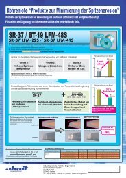
Capacitance<br />
as a function of ambient temperature T<br />
0,8<br />
-40 -30 -20 -10 0 10 20 30 40 50 60 70 80 90<br />
T [°C]<br />
Aluminium Electrolytic Capacitors<br />
The rated voltage (UR) is the voltage the capacitor is designed for. This voltage may be applied continously to the<br />
capacitor over the full temperature range.<br />
3.2 Surge voltage<br />
The Surge voltage may be applied to the capacitors only for a short time.<br />
UR � 315 V : US =1,15 * UR ( 5 times 1 min per hour)<br />
UR > 315 V : US =1,1 * UR ( 5 times 1 min per hour)<br />
3.3 Ripple voltage<br />
In many applications the voltage applied to capacitors is a combination of direct and alternating voltage. Pay attention to<br />
the following points:<br />
� The superposition of AC and DC must not exceed the rated voltage.<br />
� Reverse voltage is not allowed.<br />
� The applied ripple current must not exceed the rated ripple current.<br />
3.4 Maximum reverse voltage<br />
The Aluminium Electrolytic Capacitor is a polar component. Diodes with a max. conducting state voltage of 0.8 V could be<br />
used to prevent reverse polarity voltage. Single shorttime reverse polarity of V < 1.5 V for t < 1 s is tolerated.<br />
3.5 Rated capacitance<br />
The rated capacitance is usually determined at 100 Hz and 20 °C . In general the rated capacitance is marked on the<br />
capacitor in µF.<br />
3.6 DC and AC capacitance<br />
The capacitance determined by AC measurements is smaller than the capacitance determined by charge / discharge<br />
measurements.<br />
In most applications the capacitor is applied to an alternating voltage so in general the capacitance is measured with the<br />
AC method.<br />
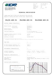
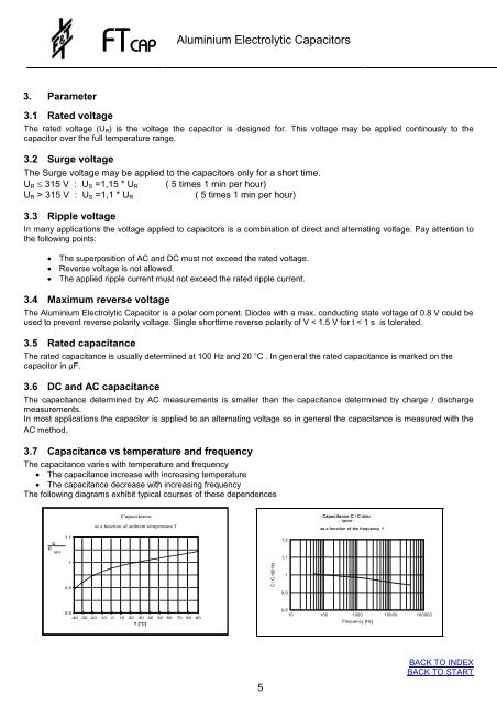
3.7 Capacitance vs temperature and frequency<br />
The capacitance varies with temperature and frequency<br />
� The capacitance increase with increasing temperature<br />
� The capacitance decrease with increasing frequency<br />
The following diagrams exhibit typical courses of these dependences<br />
5<br />
1,2<br />
1,1<br />
1<br />
0,9<br />
Capacitance C / C 100Hz<br />
- typical -<br />
as a function of the frequency f<br />
0,8<br />
10 100 1000 10000 100000<br />
Frequency [Hz]<br />
BACK TO INDEX<br />
BACK TO START