Latis II Underwater Remotely Operated Vehicle Technical Report
Latis II Underwater Remotely Operated Vehicle Technical Report
Latis II Underwater Remotely Operated Vehicle Technical Report

Create successful ePaper yourself
Turn your PDF publications into a flip-book with our unique Google optimized e-Paper software.
stability. Since the ROV is bottom heavy, the<br />
primary thrusters for forward, backward,<br />
turning, and strafing motion were mounted on<br />
the underside, allowing <strong>Latis</strong> <strong>II</strong> to maneuver<br />
easier since the thrusters’ force is applied close<br />
to the center of mass. The skids also protect the<br />
thrusters from being damaged and provide a<br />
solid stand for the ROV to sit on the pool floor.<br />
The ROV was tested in a tow tank and<br />
coefficient of<br />
13<br />
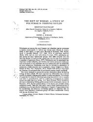
Figure 14: Main Frame Parts<br />
ARMS<br />
Many different arm design ideas were<br />
considered during this part of the design<br />
process. The team eventually decided on using<br />
Hitec 7775MG digital hobby servos for the<br />
majority of the arm linkages, and Hitec 805BB<br />
analog high toque servos for the heaviest joint-<br />
the shoulder rotation. Most joints utilized a<br />
chain and sprocket power transmission design<br />
not only for its simplicity and effectiveness, but<br />
also for the ability to use sprocket ratios to<br />
increase the power at any given connection.<br />
The range of motion for each link was decided<br />
and the corresponding sprocket ratio calculated<br />
to reach that desired range from the 180deg<br />
range of the servos. Since the range was always<br />
less than 180deg the torque available at the link<br />
would always increase proportional to the<br />
range decrease. The servos were sized for their<br />
power, size, and weight. To waterproof the<br />
servos they were dipped in Plastic Dip. A<br />
LATIS <strong>II</strong><br />
TECHNICAL REPORT<br />
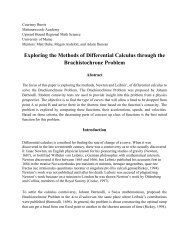
greased O-ring was installed between the servo<br />
case and the servo sprocket to protect the<br />
opening where the spline enters the case.<br />
Figure 15: Servo Waterproof Testing<br />
Lightweight plastics were utilized wherever<br />
possible for easier manufacturability and their<br />
high strength-to-weight ratios. HMWPE was<br />
used for the larger pieces of the arm and the<br />
connecting pins; a quarter inch thick PVC plate<br />
was used for the main structure of the links,<br />
and Teflon (PTFE) was used for bushings<br />
between the connecting pins and links as a soft<br />
slippery interface to reduce friction. All<br />
connections were made using press fit sizing to<br />
reduce the need for heavy metal fasteners. The<br />
grippers were designed using a rotation-tolinear<br />
linkage system and the grippers<br />
themselves were dipped in Plastic Dip to add<br />
extra grip.<br />
Figure 16: <strong>Latis</strong> <strong>II</strong> Arms