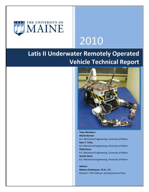
Latis II Underwater Remotely Operated Vehicle Technical Report
Latis II Underwater Remotely Operated Vehicle Technical Report
Latis II Underwater Remotely Operated Vehicle Technical Report

Create successful ePaper yourself
Turn your PDF publications into a flip-book with our unique Google optimized e-Paper software.
2010<br />
<strong>Latis</strong> <strong>II</strong> <strong>Underwater</strong> <strong>Remotely</strong> <strong>Operated</strong><br />
<strong>Vehicle</strong> <strong>Technical</strong> <strong>Report</strong><br />
Team Members:<br />
Michel Bernier<br />
B.S. Mechanical Engineering, University of Maine<br />
Ryan T. Foley<br />
B.S. Mechanical Engineering, University of Maine<br />
Philip Rioux<br />
B.S. Mechanical Engineering, University of Maine<br />
Amelia Stech<br />
B.S. Mechanical Engineering, University of Maine<br />
Advisor:<br />
Mohsen Shahinpoor, Ph.D., P.E.<br />
Richard C. Hill Professor and Department Chair
ABSTRACT<br />
For the first time, a University of Maine<br />
Mechanical Engineering Senior Capstone Design<br />
group designed and built an underwater<br />
remotely operated vehicle (ROV) and will<br />
participate in the 2010 MATE International ROV<br />
Competition. Four senior Mechanical<br />
Engineering design students have worked on<br />
preparing a prototype underwater ROV (<strong>Latis</strong> I)<br />
and their final underwater ROV (<strong>Latis</strong> <strong>II</strong>) for the<br />
competition. Missions included such tasks as<br />
sensing and measuring sound waves, accurately<br />
measuring fluid temperature, navigating<br />
through an underwater cave and collecting<br />
crustaceans and other materials from<br />
underwater and returning them to the surface.<br />
While <strong>Latis</strong> I provided much needed practice<br />
and valuable insight into designing an<br />
underwater ROV, <strong>Latis</strong> <strong>II</strong> was designed to<br />
complete the missions outlined by MATE for the<br />
competition. The UMaine ROV Team built two<br />
identical four-degree-of-freedom (DOF) arms<br />
with open-and-close grippers. To manipulate<br />
the arms on the ROV the team also built two<br />
control arms which provide feed-forward<br />
control. <strong>Latis</strong> <strong>II</strong> has a custom-made upper body<br />
structure machined from High Molecular<br />
Weight Polyethylene (HMWPE) and a stainless<br />
steel lower frame. There are six static thrusters<br />
providing six DOF control, three cameras and a<br />
holding net. Onboard control is achieved using a<br />
Compact Rio (C-Rio) which receives signals from<br />
a space navigator joystick and an Arduino<br />
2<br />
LATIS <strong>II</strong><br />
TECHNICAL REPORT<br />
micro-controller that translates information<br />
from the control arms.<br />
TABLE OF CONTENTS<br />
Abstract ....................................................... 2<br />
Budget/ Expense ......................................... 3<br />
ROV Electronics ........................................... 4<br />
Main Controller ....................................... 4<br />
Thrusters ................................................. 4<br />
Servos ...................................................... 4<br />
Sensors .................................................... 4<br />
Custom Circuit Boards ............................. 4<br />
Surface Controls .......................................... 6<br />
Main Controls .......................................... 6<br />
Arm Controls ........................................... 6<br />
Power Supply Box ................................ 6<br />
Software ...................................................... 7<br />
Design Rationale ....................................... 11<br />
Missions ................................................. 11<br />
TASK #1 – Resurrect HUGO................ 11<br />
TASK #2 – Collecting Crustaceans ...... 11<br />
TASK #3 –Sample New Vent Site ....... 12<br />
TASK #4 – AGAR Sample .................... 12<br />
ROV Design ........................................... 12<br />
Frame..................................................... 12<br />
Arms ...................................................... 13<br />
Tether .................................................... 14<br />
Thrusters ............................................... 14<br />
Cameras ................................................. 14<br />
Challenges ................................................. 15<br />
Troubleshooting Techniques .................... 15<br />
Lesson Learn/ Skills Gained ....................... 16<br />
Future Improvements ............................... 17<br />
Loihi Seamount ......................................... 18<br />
Reflections................................................. 19<br />
References ................................................ 20<br />
Acknowledgements ................................... 20
BUDGET/ EXPENSE<br />
3<br />
LATIS <strong>II</strong><br />
TECHNICAL REPORT<br />
At the beginning of the 2009-2010 academic year The UMaine ROV Team predicted a budget of<br />
$6,106.00 for the prototype and ‘start-up’ costs. For the competition ROV, the Team estimated a<br />
budget of $5,337.13 with a travel budget of $6,554.00. In total, the estimated budget for the entire<br />
project was $17,997.13. At the end of the 2009-2010 Design Year, the UMaine ROV Team spent a total<br />
of $30,024.05 in preparing, designing, building, testing and competing in the MATE Competition. It is<br />
predicted approximately 60.8% of the total cost went toward materials useable for next year’s ROV<br />
Team at the University of Maine.<br />
ITEM DESCRIPTION DISCOUNT TOTAL<br />
1 Prototype (<strong>Latis</strong> I) Materials $0.00 $1,303.35<br />
2 Competition ROV (<strong>Latis</strong> <strong>II</strong>) Materials $0.00 $2,039.36<br />
3 Cameras $0.00 $497.42<br />
4 Power Circuit Boards with Components $0.00 $401.54<br />
5 Sensors (Temperature, Humidity, Sound, Thermistor) $0.00 $346.45<br />
6 Thrusters and Drivers $3,600.00 $2,689.96<br />
7 Servo Motors $0.00 $1,051.36<br />
8 Tether Materials $0.00 $496.34<br />
9 Outsourced Manufacturing $0.00 $4,967.69<br />
10 Pilot Controls $0.00 $569.54<br />
11 Computer and Monitors $0.00 $964.94<br />
12 Power Converters $0.00 $838.36<br />
13 Onboard Controller $5,795.70 $6,279.90<br />
14 LabVIEW Software $4,699.00 $0.00<br />
15 SolidWorks Software $396.00 $0.00<br />
16 Travel Cases, T-Shirts and Shipping $0.00 $6,794.40<br />
17 Water Tank and Tools $0.00 $783.44<br />
Grand Total $14,490.70 $30,024.05<br />
Table 1: 2009-2010 UMaine ROV Budget and Expense Sheet
ROV ELECTRONICS<br />
MAIN CONTROLLER<br />
At the heart of <strong>Latis</strong> <strong>II</strong> is a National Instruments<br />
Compact RIO controller (cRio). The cRio is most<br />
commonly used for data acquisition and<br />
automation control. The cRio on <strong>Latis</strong> <strong>II</strong> has<br />
slots for four drop-in modules, of which three<br />
are used. The team used two 9401 Digital<br />
Input/ Output modules, as well as a 9205<br />
Analog Input module. These modules are used<br />
to link the cRio processor to its environment<br />
through sensors and output devices.<br />
THRUSTERS<br />
Six BTD-150 Seabotix thrusters are used on <strong>Latis</strong><br />
<strong>II</strong> for propulsion. Three Sabertooth 2x10<br />
electronic speed controllers are used to<br />
regulate thruster power. Each Sabertooth<br />
controls two thrusters.<br />
SERVOS<br />
The motion of each arm joint is provided by a<br />
small hobby servo. Eight HS-7775MG Hitec<br />
servos are used for the shoulders, elbows, and<br />
grippers. Two HS-805BB Hitec servos are used<br />
for the shoulder rotation joint. All of the servos<br />
connect back to custom circuit boards in the<br />
main enclosure for control and power signals.<br />
SENSORS<br />
To provide feedback on internal and external<br />
conditions, <strong>Latis</strong> <strong>II</strong> is equipped with a variety of<br />
sensors.<br />
4<br />
� Phidgets Temperature and Humidity<br />
Sensor Board to measure thermal<br />
conditions inside the ROV enclosure<br />
� OMEGA Thermistor for measuring<br />
external water temperature<br />
� H1a Aquarian Audio Hydrophone for<br />
measuring external sound sources<br />
LATIS <strong>II</strong><br />
TECHNICAL REPORT<br />
CUSTOM CIRCUIT BOARDS<br />
To make it easier to interface to the cRio<br />
modules, three custom printed circuit boards<br />
(PCBs) were designed and manufactured. Each<br />
PCB connects to its cRio module through a<br />
ribbon cable, and connects to various devices<br />
through three-conductor cables commonly<br />
found in radio-control hobby electronics.<br />
THRUSTER BOARD<br />
The Thruster Board breaks six digital output<br />
channels from a 9401 module on the cRio into<br />
three-pin headers for the Sabertooth units to<br />
plug into. The remaining two channels are used<br />
to control the gripper servos. Each servo pulls<br />
power from the 5V supply through a PCBmounted<br />
3A fuse.<br />
Figure 1: Thruster PWM Board<br />
To work with this PCB, the 9401 module on the<br />
cRio is configured for pulse-width-modulation<br />
(PWM) output. Each channel produces a square<br />
wave with a duty cycle proportional to the<br />
desired speed.<br />
A resistor-capacitor (RC) circuit is used to filter<br />
the pulse with modulation (PWM) signal into an<br />
analog signal for the Sabertooth. The servos<br />
require an actual PWM signal, so no filtering<br />
circuit is used.
SURFACE CONTROLS<br />
MAIN CONTROLS<br />
<strong>Latis</strong> <strong>II</strong> is capable of six degrees of motion; three<br />
axes of translation and three axes of rotation. A<br />
3D Space Navigator was used to help make the<br />
propulsion control intuitive for the pilot. The<br />
3D navigator is capable of motion in the same<br />
six axes that <strong>Latis</strong> <strong>II</strong> is, so the pilot simply moves<br />
the navigator manner that he/ she would like<br />
<strong>Latis</strong> <strong>II</strong> to move. The 3D navigator allows one<br />
handed control of the ROVs motion. Having<br />
one hand free, the pilot can use the mouse or<br />
keyboard to interact with the LabVIEW program<br />
dashboards on the computer.<br />
ARM CONTROLS<br />
<strong>Latis</strong> <strong>II</strong> features an intricate pair of arms, each<br />
one capable of four degrees of freedom.<br />
Controlling these arms through joysticks or<br />
sliders on the computer screen would be<br />
complicated and require a great deal of practice<br />
for the arm operator. Taking inspiration from<br />
arm controls seen in the FIRST Robotics<br />
Competition, <strong>Latis</strong> <strong>II</strong> has a set of control arms on<br />
the control board. These control arms contain<br />
three potentiometers for the lower joints, as<br />
well as a mini-joystick for control of the wrist<br />
and gripper. As these arms are moved to<br />
various positions, the software adjusts the<br />
servos on <strong>Latis</strong> <strong>II</strong> to match the angles read from<br />
the sensors on the control arms.<br />
The sensors are connected to an Arduino Mega<br />
controller, which sends the values to LabVIEW<br />
via serial communication. This style of arm<br />
control is significantly more intuitive for the<br />
operator, greatly reducing practice time<br />
required to become skilled at using the system.<br />
6<br />
LATIS <strong>II</strong><br />
TECHNICAL REPORT<br />
Figure 5: Control Arms<br />
POWER SUPPLY BOX<br />
An acrylic box was designed and fabricated to<br />
hold all of the power converters, video<br />
convertors, fuses, switches, camera and power<br />
connectors, and the main 40A breaker while<br />
supplying continuous air circulation to all the<br />
components. Three DC-DC converters step the<br />
supplied 48V down to 24V, 12V, and 5V for the<br />
ROV. The power supply box also contains all<br />
the connections for the video lines that allow<br />
the tether to be plugged in on one side and the<br />
VGA monitor wires run out the other. With<br />
their power box design the UMaine Team can<br />
be set up and ready to compete with their ROV<br />
in less than a minute.<br />
Figure 6: Power Supply Box
7<br />
Figure 7: ROV Pool-Side Electronics<br />
LATIS <strong>II</strong><br />
TECHNICAL REPORT
8<br />
Figure 8: Onboard ROV Electronics<br />
LATIS <strong>II</strong><br />
TECHNICAL REPORT
SOFTWARE<br />
LATIS <strong>II</strong><br />
The cRio controller on the ROV is programmed<br />
using National Instruments LabVIEW software.<br />
LabVIEW is a graphical programming language<br />
that allows users to create programming code<br />
through control block diagrams rather than<br />
traditional line code found in BASIC or C. Since<br />
most of the team did not have any experience<br />
with C or other typical controller programming<br />
languages, the graphical format of LabVIEW<br />
allowed the team to focus their efforts on the<br />
actual content of the program, rather than<br />
learning the syntax.<br />
MAIN HOST AND DASHBOARD<br />
The core component of the software is the main<br />
host program (called a virtual instrument, or<br />
VI). The main host contained the code for all of<br />
the inputs and outputs for the ROV, including<br />
sensors, thrusters, and the arms. The front<br />
panel of this VI contains displays and indicators<br />
for many of the ROVs vital functions.<br />
9<br />
Figure 9: LabVIEW Dashboard<br />
VENT MISSION SUB-VI<br />
To increase the modularity of the system, the<br />
vent mission code is broken out into a sub-VI.<br />
When performing this mission, the pilot presses<br />
a button on the dashboard to load this program<br />
separately. The program then allows the pilot<br />
LATIS <strong>II</strong><br />
TECHNICAL REPORT<br />
to record the three temperatures, chart the<br />
data, and show the judge before closing the<br />
program. Having this code as a sub-VI helps<br />
free up space on the main dashboard for other<br />
indicators. This setup also allowed the team to<br />
create and test the code for this mission before<br />
any of the code for the actual ROV was created.<br />
Figure 10: Vent Mission Dashboard
10<br />
Read 3D<br />
Navigator<br />
Convert 3D navigator signals<br />
to individual thruster values<br />
Write PWM values<br />
to thrusters<br />
Read serial<br />
string from<br />
Arduino<br />
LATIS <strong>II</strong><br />
Break serial string into<br />
individual sensor values<br />
Convert sensor values to arm<br />
servo duty cycles<br />
Update thruster power level<br />
displays on dashboard Write duty cycles<br />
to arm servos<br />
“VENT”<br />
button<br />
“Stop”<br />
button<br />
END<br />
Figure 11: <strong>Latis</strong> <strong>II</strong> Software Flowchart<br />
LATIS <strong>II</strong><br />
TECHNICAL REPORT<br />
Read sensor<br />
voltages from ROV<br />
Convert sensor voltages to<br />
real-world values<br />
Update dashboard displays<br />
for all sensors<br />
“HUGO”<br />
button<br />
VENT Mission<br />
subroutine<br />
HUGO Mission<br />
subroutine
DESIGN RATIONALE<br />
MISSIONS<br />
After establishing that the UMaine ROV team<br />
could successfully build, program and operate<br />
the prototype, <strong>Latis</strong> I, the team began the<br />
design process to create a new ROV specifically<br />
designed for the MATE ROV Competition. The<br />
team focused on compactness, efficiency,<br />
simplicity, and manufacturability in the final<br />
design. The following is a short description of<br />
the design rationale followed for each task<br />
appointed by MATE.<br />
11<br />
Figure 12: Prototype ROV, <strong>Latis</strong> I<br />
TASK #1 – RESURRECT HUGO<br />
The first mission requires the ROV to locate an<br />
area of seismic activity, release the High Rate<br />
Hyrdophone (HRH) from the elevator, and<br />
install it at that spot. Next, the ROV must open<br />
the port on HUGO’s junction box and insert the<br />
HRH’s cable. To accomplish these tasks, <strong>Latis</strong> <strong>II</strong><br />
has a hydrophone installed on the front of the<br />
body which can detect sound waves. The<br />
LabVIEW dashboard provides a graphical display<br />
of the sound waves underwater and gives a<br />
numeric value of the frequency. The ROV also<br />
has opposing four degree-of-freedom arms<br />
outfitted with grippers. This will allow the ROV<br />
to remove both pins from the HRH<br />
simultaneously and move it to the location<br />
LATIS <strong>II</strong><br />
TECHNICAL REPORT<br />
emitting the sound waves on the pool floor.<br />
<strong>Latis</strong> <strong>II</strong> has three cameras installed to give the<br />
operators multiple views of the arms and any<br />
objects the ROV needs to grab or manipulate.<br />
These multiple viewing angles allow the<br />
operator to successfully complete this task. The<br />
grippers were designed specifically to hold the<br />
elevator and HRH frame so that the ROV is<br />
stable as it removes the HRH.<br />
TASK #2 – COLLECTING CRUSTACEANS<br />
The mission involves entering an 80cm by 80cm<br />
cave, collecting crustaceans, and returning<br />
them to the surface. It is with this task in mind<br />
that the ROV Team designed such dexterous<br />
arms. The increased flexibility of the arms<br />
allows them to be particularly useful in this task<br />
as the ROV will only have to rest on the bottom<br />
of the pool as the arms do the work. Two LED<br />
lights installed on the front of the ROV allows<br />
the operator to clearly see the inside the cave.<br />
A retractable net affixed to the front of the<br />
skids makes a handy place for storing<br />
crustaceans that will be brought to the surface.<br />
Having the net on the front of the ROV provides<br />
storage space for the crustaceans so that no<br />
time has to be wasted returning to the surface<br />
to retrieve them. The overall size of the ROV<br />
was decided when designing for this task as it is<br />
the only one with a size limit. The dimensions of<br />
the ROV are 43cm wide, 60cm long and 29cm<br />
tall. This allows the ROV to maneuver freely<br />
through the cave.
12<br />
Figure 13: Arms Collecting a Crustacean<br />
TASK #3 –SAMPLE NEW VENT SITE<br />
This task requires <strong>Latis</strong> <strong>II</strong> to measure the<br />
temperature of the venting fluid in three<br />
different locations along the chimney height<br />
and collect a sample of vent spire to return it to<br />
the surface. A waterproof thermistor was<br />
installed on the right gripper to record the<br />
venting fluid temperature. This task provided<br />
another reason for the increased dexterity of<br />
the arms for the gripper needs to clamp on the<br />
tip of the vent which is at a 45deg angle and<br />
hold on until the temperature value is displayed<br />
on the computer screen. By having the<br />
thermistor situated at the end of the gripper<br />
and allowing the gripper to hold on to the vent,<br />
the ROV will be stabilized as the thermistor<br />
reads the fluid temperature. Furthermore, the<br />
net attached to the front of the ROV will allow<br />
room to store the vent sample that needs to be<br />
returned to the surface.<br />
TASK #4 – AGAR SAMPLE<br />
This mission task requires <strong>Latis</strong> <strong>II</strong> to collect a<br />
sample of a bacterial mat and return it to the<br />
surface. A special AGAR sampling tool was<br />
designed using PVC pipe and fittings to collect<br />
the proper amount of bacterial mat. The tool<br />
relies on suction power and the ability of the<br />
arms to break the surface tension of the AGAR.<br />
The depth of the AGAR sample tray was taken<br />
into account such that the diameter of the PVC<br />
LATIS <strong>II</strong><br />
TECHNICAL REPORT<br />
device was the only adjustable factor in<br />
collecting the proper volume of AGAR. The<br />
design allows for the tool to simply be pushed<br />
straight into the AGAR and then pulled out with<br />
the AGAR held by suction inside the tool. The<br />
device and AGAR fit in the net on <strong>Latis</strong> <strong>II</strong> to<br />
prevent the extra trip to the surface. Through<br />
testing, AGAR was found to hold its shape and<br />
not disintegrate when collected so the holding<br />
net could be made of simple window screening<br />
and no special alterations were required.<br />
ROV DESIGN<br />
The ROV was designed with buoyancy, strength,<br />
size, dexterity, maneuverability and stability in<br />
mind. The overall idea incorporates six simply<br />
mounted thrusters, two identical 4 DOF arms<br />
with open-close grippers, three cameras for<br />
vision, a hydrophone and a thermistor for<br />
measuring sound and temperature respectively.<br />
FRAME<br />
The ROV frame was one of the most highly<br />
discussed components for the second semester.<br />
While the simple design of the prototype with<br />
its cylindrical water proof enclosure surrounded<br />
by a metal frame was effective, it wasted<br />
valuable space for electronics and was difficult<br />
to mount components to. It was finally agreed<br />
upon to make the upper structure both<br />
waterproof and structural so that there was no<br />
need for both, square for ease of fabrication<br />
and mounting, and made out of light plastic for<br />
buoyancy and strength. The bottom plate and<br />
lower skids were made of stainless steel for<br />
weight and resistance to corrosion in water.<br />
Constructing the lower portion of the ROV out<br />
of heavy stainless steel and the top section out<br />
of buoyant plastic creates a pendulum effect in<br />
the water causing the ROV to always tend<br />
toward an upright attitude and increases its
stability. Since the ROV is bottom heavy, the<br />
primary thrusters for forward, backward,<br />
turning, and strafing motion were mounted on<br />
the underside, allowing <strong>Latis</strong> <strong>II</strong> to maneuver<br />
easier since the thrusters’ force is applied close<br />
to the center of mass. The skids also protect the<br />
thrusters from being damaged and provide a<br />
solid stand for the ROV to sit on the pool floor.<br />
The ROV was tested in a tow tank and<br />
coefficient of<br />
13<br />
Figure 14: Main Frame Parts<br />
ARMS<br />
Many different arm design ideas were<br />
considered during this part of the design<br />
process. The team eventually decided on using<br />
Hitec 7775MG digital hobby servos for the<br />
majority of the arm linkages, and Hitec 805BB<br />
analog high toque servos for the heaviest joint-<br />
the shoulder rotation. Most joints utilized a<br />
chain and sprocket power transmission design<br />
not only for its simplicity and effectiveness, but<br />
also for the ability to use sprocket ratios to<br />
increase the power at any given connection.<br />
The range of motion for each link was decided<br />
and the corresponding sprocket ratio calculated<br />
to reach that desired range from the 180deg<br />
range of the servos. Since the range was always<br />
less than 180deg the torque available at the link<br />
would always increase proportional to the<br />
range decrease. The servos were sized for their<br />
power, size, and weight. To waterproof the<br />
servos they were dipped in Plastic Dip. A<br />
LATIS <strong>II</strong><br />
TECHNICAL REPORT<br />
greased O-ring was installed between the servo<br />
case and the servo sprocket to protect the<br />
opening where the spline enters the case.<br />
Figure 15: Servo Waterproof Testing<br />
Lightweight plastics were utilized wherever<br />
possible for easier manufacturability and their<br />
high strength-to-weight ratios. HMWPE was<br />
used for the larger pieces of the arm and the<br />
connecting pins; a quarter inch thick PVC plate<br />
was used for the main structure of the links,<br />
and Teflon (PTFE) was used for bushings<br />
between the connecting pins and links as a soft<br />
slippery interface to reduce friction. All<br />
connections were made using press fit sizing to<br />
reduce the need for heavy metal fasteners. The<br />
grippers were designed using a rotation-tolinear<br />
linkage system and the grippers<br />
themselves were dipped in Plastic Dip to add<br />
extra grip.<br />
Figure 16: <strong>Latis</strong> <strong>II</strong> Arms
TETHER<br />
The tether supplies <strong>Latis</strong> <strong>II</strong> with power and<br />
communication. It is composed of four 10g<br />
power cables, one 35mm coaxial audio cable, 3<br />
coaxial camera cables with BNC connectors and<br />
incorporated power, and a single CAT5e<br />
Ethernet cable. The team designed the tether to<br />
be neutrally buoyant for the first 15 feet to<br />
allow <strong>Latis</strong> <strong>II</strong> to maneuver without much tether<br />
drag. This was extremely important considering<br />
the ROV needs to travel freely through the<br />
underwater cave.<br />
THRUSTERS<br />
The team decided to use six high quality<br />
thrusters from Seabotix for their propulsion<br />
system. The team chose these because of the<br />
frequency with which MATE ROV Competition<br />
Teams have used them in the past and Seabotix’<br />
discount to MATE Teams. While four thrusters<br />
were tested on the prototype, six thrusters<br />
were installed on <strong>Latis</strong> <strong>II</strong> to provide extra power<br />
and maneuverability. The positioning of the<br />
thrusters provided maximum dexterity for the<br />
ROV to move in all six dimensions with ease.<br />
14<br />
Figure 17: Thruster Arrangement<br />
Cost, voltage and amperage were the three<br />
main driving factors for the team’s decision to<br />
use three Dimension Engineering Sabertooth<br />
2X10 motor controllers to drive the thrusters.<br />
LATIS <strong>II</strong><br />
TECHNICAL REPORT<br />
CAMERAS<br />
Vision was a high priority for the team as it<br />
allows for smoother operation by the pilot and<br />
arm operator. Two cameras are mounted on<br />
the top of the ROV and can be infinitely<br />
adjusted in all directions. The third camera is<br />
mounted inside the ROV and looks through a<br />
window directly at any task that the arms may<br />
be completing and can also see the attitude of<br />
the retractable net. The two waterproof<br />
cameras on the outside of the ROV have wideangle<br />
lenses allowing them to see as much of<br />
the playing field as possible, while the indoor<br />
camera has a slightly smaller aperture giving it a<br />
more defined and detailed view of the<br />
immediate front of the ROV.<br />
Figure 18: Control Monitors and power supply box<br />
Two computer monitors are used to provide<br />
views from all three cameras by way of a video<br />
switcher, while a third is dedicated to the<br />
LabVIEW dashboard.
CHALLENGES<br />
One of the most difficult challenges faced by<br />
the UMaine Team was preparing the ROV to<br />
operate in a submerged environment. Due to<br />
the extensive electronic systems both inside<br />
and outside the electronics enclosure, excellent<br />
waterproofing processes were essential. To<br />
address this challenge, initial testing was<br />
conducted on prototype, <strong>Latis</strong> I. The<br />
information gained from these tests influenced<br />
the final ROV design. For example, difficulties<br />
with small leaks through the waterproof<br />
connectors led to a final design with a<br />
permanent wire configuration and only<br />
installing a single removable part to access the<br />
sealed enclosure. Furthermore, sealing<br />
compounds such as potting epoxy were used<br />
more on <strong>Latis</strong> <strong>II</strong> because of the hardening<br />
capabilities not observed when using silicone or<br />
polyurethane.<br />
Another challenge faced by the team was<br />
dealing with conflicting opinions within the<br />
group regarding the steps to address a technical<br />
issue or the particular technical issue itself. It<br />
became obvious to the team that a process for<br />
resolving such conflicts would increase the<br />
productivity while avoiding interpersonal<br />
aggravations. To solve this problem it was<br />
agreed upon that testing would be conducted,<br />
when possible, on each idea to determine its<br />
viability. The criterion for selection was based<br />
on design parameters for our project such as<br />
cost, reliability, ease of implementation, and<br />
integration into existing systems. This process<br />
allowed a comparison between the ideas of the<br />
individual, and the goals of the team, usually<br />
resulting in one idea that best fit the situation<br />
at hand.<br />
15<br />
LATIS <strong>II</strong><br />
TECHNICAL REPORT<br />
Finally, one of the biggest challenges was<br />
manufacturing the parts for <strong>Latis</strong> <strong>II</strong>. After<br />
spending more time and effort than anticipated<br />
on <strong>Latis</strong> I it was decided early on in designing<br />
<strong>Latis</strong> <strong>II</strong> that the team should outsource<br />
manufacturing responsibilities to a company<br />
that specializes in the task. This however did<br />
not work well due to the slow turn-around time<br />
of the parts and frequent mistakes made by the<br />
manufacturing company. To solve this problem,<br />
the team decided to learn how to operate the<br />
Computer Numerically Controlled (CNC)<br />
machine available in the lab and manufacture<br />
some of the simpler parts. The team fabricated<br />
the remainder of the parts needed to finish the<br />
ROV, control arms and power supply box.<br />
TROUBLESHOOTING TECHNIQUES<br />
To gain some knowledge and experience that<br />
the UMaine ROV Team could later call upon<br />
when troubleshooting issues on <strong>Latis</strong> <strong>II</strong>, the<br />
team designed and constructed their prototype<br />
<strong>Latis</strong> I in the fall of 2009. From this first attempt<br />
the team gained valuable insight into the things<br />
that may go wrong in the future.<br />
WATERPROOFING<br />
In designing <strong>Latis</strong> I the team decided to use<br />
factory-made water proof electrical connectors.<br />
However, finding such connectors at the 40A<br />
current rating was problematic. Furthermore,<br />
the waterproof connectors finally purchased<br />
ended up being the weakest link in the entire<br />
electronics enclosure for <strong>Latis</strong> I. After weeks of<br />
trying different techniques such as greasing the<br />
O-rings of the connectors, tightening the<br />
connectors more than the specified torque, and<br />
even creating a positive pressure inside the<br />
electronics compartment, the team was still
attling leaks. Hours of research was conducted<br />
into finding better waterproof connectors.<br />
When searching for connectors finally failed to<br />
produce anything useful and legally sold in the<br />
US, the team switched tactics and decided to<br />
run the wires through air fittings which were<br />
then tapped into the walls of the ROV body.<br />
When the wire was sealed into this fitting and<br />
the fitting threaded into the body, a water tight<br />
seal was made and still allowed for the fitting<br />
and component to be removed if necessary.<br />
PROGRAMMING<br />
By using the NI C-rio early on in the prototype<br />
process the UMaine ROV Team was able to<br />
encounter and fix as much of the programming<br />
bugs as possible before beginning work in the<br />
more complicated <strong>Latis</strong> <strong>II</strong>. Troubleshooting the<br />
ROV control program involved either consulting<br />
the team’s resident LabVIEW expert or<br />
contacting the technical support provided by<br />
National Instruments. With both of these<br />
resources, the team was able to effectively<br />
diagnose and solve significant programming<br />
problems.<br />
By far the most commonly used<br />
troubleshooting technique was teamwork.<br />
Working as a team allowed the most productive<br />
use of time and netted the best results. Once<br />
ideas were considered and then decided upon<br />
the problem usually was solved by utilizing<br />
other internal and external resources.<br />
LESSON LEARN/ SKILLS GAINED<br />
The problem with manufacturing that the team<br />
learned is one that is undoubtedly inherent in<br />
any design project and definitely provides room<br />
for new skills to be gained. The lesson learned is<br />
when relying on a company to produce vital<br />
16<br />
LATIS <strong>II</strong><br />
TECHNICAL REPORT<br />
components, it is critical that the team monitors<br />
the progress closely to avoid delays. If there are<br />
problems, the team can decide early on what<br />
actions need to be taken to resolve the issue.<br />
As noted before, having learned from the time<br />
needed to complete the parts for <strong>Latis</strong> I, the<br />
team decided to send out <strong>Latis</strong> <strong>II</strong> parts to a third<br />
party. The company, however, was unable to<br />
deliver the parts as scheduled, or to the<br />
specifications requested. This left the ROV team<br />
with less material, money and time with which<br />
to troubleshoot and complete their design.<br />
Fortunately, there were good results from this<br />
situation. The team stepped up to the plate and<br />
took control of their product. Team members<br />
worked day and night on the manual milling<br />
and turning machines as well as the CNC. Parts<br />
were retrieved from the manufacturer and<br />
finished in the team’s lab. Team members<br />
learned how to machine parts and to refabricate<br />
already manufactured components.<br />
Time-management became even more of a<br />
priority as the team had even less time than<br />
anticipated so they worked to gain lab access<br />
during the nights and weekends.<br />
In all, the team learned a valuable lesson in<br />
taking control of their own design and gained<br />
skills in machining, quality control, and time<br />
management. Furthermore, the team gained<br />
skills in diplomacy and professional<br />
correspondence in working with the<br />
manufacturing company to fix the problem.<br />
Through teamwork and dedication, the UMaine<br />
ROV Team was able to overcome the problem<br />
and still produce a quality product in the time<br />
available for the project.
FUTURE IMPROVEMENTS<br />
Throughout the entire design process the ROV<br />
Team had to continuously change, alter and in<br />
some cases completely remove or disregard<br />
design components and ideas. Some of these<br />
ideas, if they had been followed through, could<br />
have made great designs. The following are<br />
some design ideas the team would like to see<br />
either pursued and integrated or improved<br />
upon.<br />
PROPULSION<br />
Early in the design of the prototype the team<br />
battled with designing the best propulsion<br />
system for the ROV. Ideas ranged from belts<br />
and flippers to hydraulics and pneumatics. One<br />
idea that continuously surfaced, however, is<br />
that of dynamic thrusters. With dynamic<br />
thrusters, the same thrusters from Seabotix<br />
could be used but instead of being statically<br />
mounted to the body of the ROV they would be<br />
mounted to rotatable plates such that they<br />
could turn up to 360deg. This would allow a<br />
single thruster to control at least two axis of<br />
motion instead of just one when statically<br />
mounted. Servos or any kind of motor<br />
electrically driven or otherwise could be used to<br />
rotate the thruster. The team would be able to<br />
literally double their effectiveness with each<br />
thruster and therefore cut the number of<br />
thrusters, and motor drivers in half. The<br />
downside of this is making the device that<br />
would have to turn the thruster and then<br />
integrating the extra control specifications into<br />
the control program.<br />
17<br />
LATIS <strong>II</strong><br />
TECHNICAL REPORT<br />
WATERPROOFING<br />
Being one of the most, if not the most, difficult<br />
problems plaguing the ROV team;<br />
waterproofing techniques and design could be<br />
improved. If the design had taken into account<br />
more water tight compartments and less thruwall<br />
connections the waterproofing would have<br />
been much easier. Furthermore, using less<br />
electronics would also help in this respect (i.e.<br />
hydraulic or pneumatic propulsion/power<br />
system that is already inherently waterproof).<br />
KEEP IT SIMPLE STUPID (KISS)<br />
Even with the team’s best efforts to try and<br />
make the design as simple as possible without<br />
compromising function, the project still proved<br />
to be far too complicated to complete in the<br />
time allotted and with the people and resources<br />
available. The team would like to see future<br />
teams drastically cut down on the complexity of<br />
the manufactured parts and the overall design.<br />
Although many pre-made parts were<br />
researched and considered for the ROV design,<br />
a huge number of components still had to be<br />
custom fabricated. Taking less time and effort<br />
to make custom parts would leave more time to<br />
practice with the ROV and prepare it for<br />
competition.
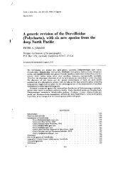
LOIHI SEAMOUNT<br />
The Loihi seamount is Hawaii’s youngest<br />
underwater volcano located 30 km off the<br />
southern coast of the Big Island. Rising more<br />
than 3,000m above the sea floor, it is taller than<br />
Mt. St. Helens was before its catastrophic<br />
eruption in 1980. However, with the peak of the<br />
seamount being a thousand meters below the<br />
surface, exploration of the area has not been a<br />
simple process. In 1996, a large earthquake<br />
swarm at the seamount brought new attention<br />
to the area. Researchers found evidence that<br />
Loihi had erupted during the earthquake. This<br />
was the first ever confirmed historical recording<br />
of the seamount’s volcanic activity. Scientific<br />
communities changed their view of Loihi from<br />
that of a dormant seamount to an active<br />
undersea volcano.<br />
18<br />
Figure 19: Digital Terrain Model of Loihi<br />
Research of the Loihi seamount has been<br />
conducted in large part by the University of<br />
Hawaii’s Undersea Research Laboratory (HURL),<br />
operated through the School of Ocean and<br />
Earth Science and Technology (SOEST). The<br />
Hawaii Undersea Geo-Observatory (HUGO) was<br />
developed to record seismic activity, sound<br />
within the water, and pressure changes. As an<br />
automatic observatory, Hugo’s information is<br />
LATIS <strong>II</strong><br />
TECHNICAL REPORT<br />
sent through a fiber optic cable along the ocean<br />
floor to a seaside station. Information is sent<br />
from there to the University Hawaii for analysis.<br />
Professor Fred Duennebier from Hawaii’s<br />
School of Ocean and Earth Science and<br />
Technology was the project leader for the Hugo<br />
venture.<br />
Figure 20: HUGO<br />
When contacted by our team, he offered some<br />
updated information about Hugo’s current<br />
status. The cable to HUGO developed a short to<br />
sea water about 6 months after it was installed.<br />
The observatory was later recovered by JASON<br />
in 2004 and has now been reconfigured for reinstallation<br />
at the ALOHA Cabled Observatory<br />
north of Oahu.<br />
Projects like HUGO and the ALOHA observatory<br />
continue to be vital assets for researching and<br />
exploring the vast ocean realms.
REFLECTIONS<br />
MIKE BERNIER<br />
As team leader/manager I feel that I had some<br />
of the greatest responsibilities of the team. I<br />
learned a lot from pushing myself as a leader<br />
and as an engineer. This was a very timeconsuming<br />
and resolve-testing project that<br />
brought out some of the best and worst in me<br />
as a leader and I applaud my team for taking<br />
both with acceptance and criticism. I can only<br />
hope to take what I have learned over these<br />
past months and apply it to everything I do in<br />
my professional career to come. I would also<br />
like to thank all of our supporters, advisors,<br />
family and friends in their contributions of time<br />
and resources to our project.<br />
RYAN FOLEY<br />
Working on the electronics and programming of<br />
the ROVs was a rewarding experience. After<br />
seeing many control styles through other<br />
robotics competitions, I was thrilled that the<br />
team was able to implement the feed-forward<br />
control arms. Not being limited to a certain set<br />
of allowable parts, as is the case in other<br />
competitions I have been a part of, was a<br />
unique experience. Being able to research,<br />
compare, select, and implement a variety of<br />
parts and systems was good practice for realworld<br />
engineering. Working on the ROV was a<br />
rewarding opportunity to work on a robotics<br />
project that was out of my comfort zone.<br />
19<br />
LATIS <strong>II</strong><br />
TECHNICAL REPORT<br />
PHILIP RIOUX<br />
Learning the process of integrating software<br />
with electrical components, and hardware, has<br />
been my greatest professional accomplishment<br />
of the <strong>Latis</strong> project. Understanding the entire<br />
process allows me to design the hardware with<br />
the software in mind. I am grateful to the MATE<br />
organization for offering me, through the ROV<br />
competition, a venue to grow my understanding<br />
of the design process, as well as develop many<br />
new technical skills that will serve me well in my<br />
career for years to come.<br />
AMELIA STECH<br />
Establishing the first ROV team from the<br />
University of Maine has been rewarding and<br />
challenging. Having no previous experience in<br />
robotics, machining and programming, working<br />
on the <strong>Latis</strong> project expanded my knowledge<br />
tremendously. I focused on the electrical<br />
components of the ROV and was able to gain a<br />
hands-on-experience in what goes on to<br />
communicate with the main components.<br />
Documenting everything that was considered<br />
and done showed to be a helpful task. I am<br />
proud to be a part of one of the hardest<br />
working and dedicated capstone teams which<br />
set a solid foundation for future MATE<br />
Competitions.
REFERENCES<br />
School of Ocean and Earth Science and Technology:<br />
http://www.soest.hawaii.edu/SOEST_News/News/SOESTinthenews2002.htm)<br />
Hawaiian Center for Volcanology<br />
http://www.soest.hawaii.edu/GG/HCV/loihi.html<br />
20<br />
LATIS <strong>II</strong><br />
TECHNICAL REPORT<br />
Figure 19 Photo Courtesy of:<br />
http://oceanexplorer.noaa.gov/explorations/02hawaii/background/plan/media/pearl_hermes_atoll.ht<br />
ml )<br />
Figure 20 Photo Courtesy of: Professor Fred Duennebier<br />
National Instruments<br />
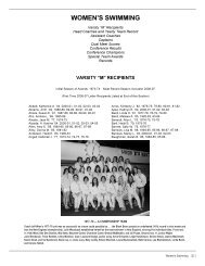
ACKNOWLEDGEMENTS<br />
The UMaine ROV Team would like to thank everyone who helped us with this project.<br />
Art Pete<br />
David Morrison<br />
Department of Mechanical Engineering<br />
Justin Poland<br />
Karen Fogarty<br />
Mohsen Shahinpoor<br />
Neal Greenberg<br />
Patrick Bates<br />
Professor Fred Duennebier<br />
Victoria Blanchette<br />
2011 ROV Team<br />
Figure 21: 2010 UMaine ROV Team