A USRP-based Testbed for OFDM-based Radar and ... - CEL - KIT
A USRP-based Testbed for OFDM-based Radar and ... - CEL - KIT
A USRP-based Testbed for OFDM-based Radar and ... - CEL - KIT
- TAGS
- testbed
- radar
- cel.kit.edu

You also want an ePaper? Increase the reach of your titles
YUMPU automatically turns print PDFs into web optimized ePapers that Google loves.
A <strong>USRP</strong>-<strong>based</strong> <strong>Testbed</strong> <strong>for</strong> <strong>OFDM</strong>-<strong>based</strong><br />
<strong>Radar</strong> <strong>and</strong> Communication Systems<br />
Martin Braun, Marcus Müller, Manuel Fuhr, <strong>and</strong> Friedrich K. Jondral<br />
Communications Engineering Lab, Karlsruhe Institute of Technology (<strong>KIT</strong>), Germany<br />
Kaiserstr. 12<br />
D-76133 Karlsruhe, Germany<br />
Email: martin.braun@kit.edu<br />
Phone: +49 721 608 43790<br />
Index Terms—<strong>OFDM</strong> <strong>Radar</strong>, Software Defined Radio, <strong>USRP</strong><br />
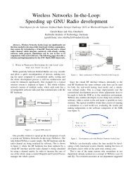
Abstract—In this paper, we present a measurement testbed <strong>for</strong><br />
<strong>OFDM</strong> radar which uses <strong>USRP</strong>s as a front-end. The resulting<br />
system, using two <strong>USRP</strong>s <strong>and</strong> a laptop, requires little power<br />
<strong>and</strong> can thus be easily installed in vehicles to per<strong>for</strong>m measurements<br />
<strong>for</strong> car-to-car or car-to-infrastructure applications. As an<br />
example, we show how signals parametrized according to the<br />
IEEE 802.11a/p st<strong>and</strong>ards can be enhanced by radar functions<br />
without any additional spectrum usage <strong>and</strong> only a little extra<br />
signal processing.<br />
I. INTRODUCTION<br />
Over the last two years, <strong>OFDM</strong> has become a focus of<br />
research <strong>for</strong> use in mobile networks which combine radar<br />
<strong>and</strong> communications in a single system [1], [2]. Such systems<br />
use in<strong>for</strong>mation-bearing <strong>OFDM</strong> signals as radar signals, which<br />
allows both a communication usage (other systems can receive<br />
<strong>and</strong> decode this signal) as well as radar functionality (by receiving<br />
reflections of the own transmitted signal) with a single<br />
access to the medium. Combined radar <strong>and</strong> communication<br />
systems thus save spectrum usage, <strong>and</strong> any <strong>OFDM</strong> transmitter<br />
can be upgraded with radar features simply by adding a<br />
receiver <strong>and</strong> some digital signal processing. If a receiver chain<br />
is already present, the additional hardware requirements are<br />
further alleviated.<br />
In our previous publications, the application we have focussed<br />
on most was vehicular systems. Both radar <strong>and</strong> communication<br />
systems are becoming more important in future<br />
concepts <strong>for</strong> traffic safety. Some systems are already available,<br />
such as radar-aided adaptive cruise control systems or lanechange<br />
assistants; others, such as car-to-car communications,<br />
are still subject of research but are expected to be integrated<br />
into commercially available vehicles in the near future.<br />
Using a technique – such as <strong>OFDM</strong> radar – which combines<br />
both functions has several advantages. From a technical point<br />
of view, it enables synergy effects between the systems, e.g.<br />
by allowing the radar system to communicate with other<br />
participants in the network <strong>and</strong> thus creating a cooperative<br />
radar system. An economical advantage is that a fusion of<br />
the two sub-systems makes it worth deploying communication<br />
components <strong>for</strong> vehicles even if the density of participating<br />
vehicles is too small to justify a communication-only device.<br />
In previous publications, we have shown through simulations<br />
<strong>and</strong> measurements [3] that <strong>OFDM</strong> radar systems work<br />
both theoretically <strong>and</strong> practically. However, what is lacking is<br />
a simple, small, portable <strong>and</strong> easily modifiable testbed.<br />
In this paper, we present a software radio-<strong>based</strong> approach<br />
using Universal Software Radio Peripherals (<strong>USRP</strong>s), which<br />
was first described in [4]. Although this hardware is not<br />
optimized <strong>for</strong> radar applications, we can still show that the<br />
principle works well.<br />
This paper is structured as follows: in the following section,<br />
we will explain the basics of an <strong>OFDM</strong> radar system <strong>and</strong> go<br />
into some details about the wave<strong>for</strong>ms used. Sections III <strong>and</strong><br />
IV will describe the measurement setup <strong>and</strong> show some results,<br />
respectively. Finally, section V concludes.<br />
II. <strong>OFDM</strong> RADAR BASICS<br />
Like any other radar system, <strong>OFDM</strong> radar works by transmitting<br />
a signal <strong>and</strong> receiving reflections of this signal from<br />
objects in the path of the signal’s wavefront. The big difference<br />
is that the signal transmitted was not designed <strong>for</strong> radar<br />
purposes (such as an FMCW signal) but to convey in<strong>for</strong>mation.<br />
To then achieve radar imaging requires some signal processing,<br />
the basics of which are described very briefly in this section.<br />
For a more detailed explanation of the algorithm we refer to<br />
previous publications, e.g. [2], [5].<br />
<strong>OFDM</strong> radar per<strong>for</strong>ms one measurement per frame, which<br />
describes a set of M consecutive <strong>OFDM</strong> symbols. Every<br />
<strong>OFDM</strong> symbol uses N active carriers to transmit (e.g. <strong>for</strong><br />
<strong>OFDM</strong> signals following the IEEE 802.11a/p st<strong>and</strong>ard, N<br />
would be 53 including an empty DC carrier). As in previous<br />
publications, we denote a transmitted <strong>OFDM</strong> frame by a<br />
matrix,<br />
⎛<br />
⎞<br />
FTx =<br />
⎜<br />
⎝<br />
c0,0 ··· c0,M−1<br />
c1,0 ··· c1,M−1<br />
.<br />
. ..<br />
cN−1,0 ··· cN−1,M−1<br />
.<br />
⎟<br />
⎟.<br />
(1)<br />
⎠<br />
In plain language, every row of the matrix corresponds to the<br />
data on one sub-carrier, whereas every column corresponds to<br />
the data on one <strong>OFDM</strong> symbol. One element ck,l from this<br />
matrix is a complex value from a modulation alphabet, most
often BPSK or QPSK. A transmit matrix can be converted into<br />
a transmit signal simply by<br />
• applying an IFFT of length NTotal on every column,<br />
• adding a cyclic prefix <strong>and</strong><br />
• digital/analog converting it.<br />
This matrix is there<strong>for</strong>e equivalent to the actual signal transmitted<br />
if the following parameters are known:<br />
• The sub-carrier distance ∆f, <strong>and</strong> there<strong>for</strong>e the <strong>OFDM</strong><br />
symbol duration T = 1/∆f.<br />
• The duration of the cyclic prefix (or guard interval), TG.<br />
• The sampling rate fS after the IFFT. Note that this<br />
determines the sub-carrier distance by ∆f = fS<br />
NTotal .<br />
• The centre frequency fC.<br />
While transmitting, a receiver is active to pick up backscattered<br />
signals. It is important that the receiver is exactly<br />
synchronous to the transmitter, meaning that there must be<br />
no time or frequency offset. If these conditions are met, a<br />
received signal can also be represented by a matrix,<br />
�<br />
H−1<br />
(FRx)k,l = bh(FTx)k,l ·e j2πTOfD,hl −j2πτh∆fk jϕh ·e ·e<br />
h=0<br />
+( ˜ Z)k,l.<br />
Here, H denotes the number of reflecting targets. Every target<br />
has a distance dh, which translates into a delay τh of the<br />
corresponding signal. fD,h is its Doppler shift, <strong>and</strong> ϕh is a<br />
r<strong>and</strong>om, unknown phase shift. The attenuation bh <strong>for</strong> each<br />
target can be approximated by the point-scatter model [6],<br />
�<br />
c0σRCS,h<br />
bh =<br />
(4π) 3d4 hf2 C<br />
(2)<br />
, (3)<br />
where σRCS,h is the radar cross section. The matrix Z ∈<br />
C N×M represents white Gaussian noise.<br />
The transmit symbols are still in the receive matrix. We<br />
eliminate these by element-wise division, yielding<br />
(F)k,l =<br />
H−1 �<br />
h=0<br />
bhe j2πlTOfD,h e −j2πkτh∆f e jϕh +(Z)k,l. (4)<br />
Thus, from the incoming samples, we can very simply<br />
calculate a matrix F which contains complex sinusoids on its<br />
columns <strong>and</strong> rows. The radar problem is there<strong>for</strong>e trans<strong>for</strong>med<br />
into a detection <strong>and</strong> identification of sinusoids.<br />
To tackle this problem, we have proposed several approaches,<br />
such as the periodogram [2], [5] <strong>and</strong> parametric<br />
methods [7]. For this work, the periodogram-<strong>based</strong> technique<br />
is used.<br />
The periodogram is a good, in some cases optimal approach<br />
<strong>for</strong> the identification of sinusoids in time-discrete, onedimensional<br />
signals [8]. Here, we extend it to two dimensions,<br />
yielding<br />
PerF(n,m) =<br />
� �<br />
1<br />
�NPer−1<br />
� � MPer−1 �<br />
�<br />
NM �<br />
k=0<br />
l=0<br />
lm −j2π M (F)k,l(W)k,le Per<br />
� �2<br />
� kn j2π � N e Per�<br />
.<br />
�<br />
(5)<br />
The result is a discrete periodogram with dimensions<br />
NPer × MPer, which are usually chosen as integer multiples<br />
of N <strong>and</strong> M, respectively. The first step is an element-wise<br />
multiplication with the matrix W, a window matrix, which is<br />
created by the dyadic product<br />
1<br />
W =<br />
�wd�2�wv�2wT r ⊗wv, wr ∈ R 1×N , wv ∈ R 1×M ,<br />
(6)<br />
where wd <strong>and</strong> wv are one-dimensional windows, such as<br />
Dolph-Chebyshev windows. The normalization factor fixes the<br />
matrix to unit Frobenius norm, allowing us to switch window<br />
types without change the total energy of the periodogram.<br />
By using FFTs <strong>and</strong> IFFTs to calculate the periodogram, this<br />
method can be implemented very efficiently. Further optimization<br />
can be achieved by preselecting a part of the periodogram<br />
which is most likely to contain relevant in<strong>for</strong>mation, thereby<br />
cropping the periodogram to a smaller size than NPer×MPer.<br />
Fig. 1 shows a schematic of such a radar <strong>and</strong> communication<br />
system. The signal processing chain has been developed <strong>and</strong><br />
tested in Matlab, it is currently being ported to GNU Radio<br />
to eliminate the need <strong>for</strong> the Matlab runtime <strong>and</strong> increase<br />
per<strong>for</strong>mance.<br />
Detecting <strong>and</strong> identifying targets corresponds to the detection<br />
of peaks in the periodogram. If a peak is found at indices<br />
(ˆn, ˆm), this corresponds to an estimated target distance of<br />
<strong>and</strong> a relative velocity of<br />
ˆv =<br />
ˆd = ˆnc0<br />
, (7)<br />
2∆fNPer<br />
ˆmc0<br />
2fCTOMPer<br />
. (8)<br />
The range resolution of an <strong>OFDM</strong> radar system is given<br />
by its b<strong>and</strong>width whereas its Doppler resolution is determined<br />
by the duration of a frame. However, since the matrix F is<br />
discrete in nature, there are maximum unambiguous ranges<br />
<strong>and</strong> relative velocities,<br />
dunamb = c0<br />
, (9)<br />
2∆f<br />
vunamb = . (10)<br />
2fc ·TO<br />
Objects at distances d <strong>and</strong> d+dunamb can not be distinguished.<br />
If these values are chosen large enough, this is not a problem<br />
since further objects are less likely to reflect enough energy to<br />
appear above the noise floor in any case. However, <strong>for</strong> large<br />
sub-carrier distances it is not unlikely that large objects (e.g.<br />
buildings) far away may eclipse a smaller object close by.<br />
A. IEEE 802.11a signals<br />
Our combination of (unmodified) <strong>USRP</strong>s <strong>and</strong> XCVR2450<br />
daughterboards allows only b<strong>and</strong>widths below 36 MHz due<br />
to the MAX2829 transceiver IC used on said daughterboard.<br />
Since b<strong>and</strong>width fundamentally affects the range resolution,<br />
this brings some disadvantages <strong>and</strong> does not allow to reproduce<br />
the exact measurements per<strong>for</strong>med in [3]. However, it<br />
is enough to use <strong>OFDM</strong> signals parametrized according to<br />
c0
Distance (m)<br />
Distance (m)<br />
200<br />
150<br />
100<br />
50<br />
0<br />
200<br />
150<br />
100<br />
50<br />
0<br />
Analog<br />
Domain<br />
Rx<br />
Front-end<br />
Tx<br />
Front-end<br />
A/D<br />
Converter<br />
D/A<br />
Converter<br />
−100 0<br />
Relative speed (m/s)<br />
100<br />
(a) Continuous carrier allocation.<br />
−100 0<br />
Relative speed (m/s)<br />
100<br />
CP<br />
Removal<br />
CP<br />
Adder<br />
<strong>OFDM</strong><br />
(De-)Modulation<br />
FFT NTotal<br />
IFFT NTotal<br />
Data<br />
F RX<br />
F TX<br />
Modulator<br />
Fig. 1: Schematic of an <strong>OFDM</strong> radar system<br />
−70<br />
−80<br />
−90<br />
−100<br />
−70<br />
−80<br />
−90<br />
−100<br />
(b) Empty DC carrier. The third target is only barely visible among the<br />
spur floor from the closest target.<br />
Fig. 2: Simulated periodograms <strong>for</strong> three targets<br />
the IEEE 802.11a/p st<strong>and</strong>ards [9] which operate at channel<br />
b<strong>and</strong>widths of 5, 10 or 20 MHz.<br />
<strong>OFDM</strong> signals according to this st<strong>and</strong>ard use N = 53<br />
carriers, including the DC carrier which is left empty to avoid<br />
spurs typically induced by direct conversion architectures. The<br />
number of <strong>OFDM</strong> symbols is not specified in the st<strong>and</strong>ard, but<br />
determined by the number of bits transmitted per packet.<br />
At the 20 MHz channel spacing, the sub-carrier distance is<br />
∆f = 20MHz/64 = 312.5kHz. This corresponds to a unambiguous<br />
range ofdunamb = 480m. However, the periodogram is<br />
Distance (m)<br />
150<br />
100<br />
50<br />
0<br />
Divider<br />
Periodogram<br />
Calculation<br />
FFT M FFT<br />
IFFT NFFT<br />
� � � 2<br />
Crop<br />
−50 0 50<br />
Relative speed (m/s)<br />
20<br />
0<br />
−20<br />
−40<br />
Fig. 3: Spur floor measured with the <strong>USRP</strong> setup.<br />
only an effective tool if all sub-carriers are allocated. Since the<br />
DC carrier is left at zero value, the periodogram is calculated<br />
with an “incomplete” matrix F, which results in spurs. Fig. 2<br />
illustrates how these affect the periodogram; they effectively<br />
reduce the dynamic range at a given Doppler value at which at<br />
least one target was detected <strong>and</strong> can thus overshadow targets<br />
reflecting less energy. For a more detailed explanation on this<br />
phenomenon, we refer to [10].<br />
An easy solution to this problem is to skip every second<br />
carrier (including the one at DC). This way, the entire<br />
b<strong>and</strong>width is sampled at regular intervals, thus avoiding the<br />
a<strong>for</strong>ementioned spurs. Skipping half of the sub-carriers comes<br />
with two side effects: First, half of the energy used <strong>for</strong><br />
transmission is not used <strong>for</strong> the radar imaging. However, since<br />
both our test setup as well as typical wi-fi base stations have a<br />
much larger power output than typical vehicular radar systems,<br />
this is not a major drawback. Far worse is the reduction of the<br />
unambiguous range. Since ∆f is effectively doubled, dunamb is<br />
reduced to 240m.<br />
Avoiding both DC-carrier related spurs <strong>and</strong> unambiguous<br />
range reduction can only be achieved by using non-st<strong>and</strong>ard<br />
<strong>OFDM</strong> signals, e.g. by doubling the number of sub-carriers<br />
<strong>and</strong> thereby reducing the sub-carrier distance be<strong>for</strong>e skipping
every second carrier.<br />
The possibility of avoiding DC-carrier related spur floors<br />
is another advantage of our <strong>OFDM</strong> radar approach over other<br />
approaches, such as in [11], which use correlation between<br />
transmit <strong>and</strong> receive signals in the time domain.<br />
B. Use case: Dual Vehicle-to-infrastructure <strong>and</strong> radar system<br />
In the same context with car-to-car communications, carto-infrastructure<br />
communications has also been proposed as<br />
means to connect vehicles to the internet. Base stations located<br />
at the road side might use the 802.11a/p to connect with<br />
vehicles. Using <strong>OFDM</strong> radar, such a base station can be easily<br />
upgraded with a radar component.<br />
Such systems could be used to gather traffic statistics,<br />
including vehicles’ velocities, or even in the context of traffic<br />
en<strong>for</strong>cement.<br />
III. MEASUREMENT SETUP<br />
Our measurement setup consists of two <strong>USRP</strong> N210, each<br />
equipped with XCVR2450 daughterboards to allow transmission<br />
<strong>and</strong> reception in the 5 GHz range. The <strong>USRP</strong>s are synchronized<br />
using a MIMO connector cable which also allows<br />
to control both devices using a single Ethernet connection.<br />
Fig. 4: The measurement setup, showing both <strong>USRP</strong>s, the<br />
controlling laptop <strong>and</strong> the horn antennas<br />
We used different antennas depending on the measurement<br />
setup. For stationary measurements, we used horn antennas<br />
with a very high gain of 18.5dBi (see Fig. 4), which allows<br />
<strong>for</strong> very controlled experiments <strong>and</strong> reduces direct coupling.<br />
For mobile measurements, the <strong>USRP</strong>s were connected to patch<br />
antennas installed into the rear bumper of a VW Sharan.<br />
In their current version, an unmodified <strong>USRP</strong> can receive<br />
<strong>and</strong> transmit at sampling rates up to 50 Msps. As mentioned<br />
be<strong>for</strong>e, the available b<strong>and</strong>width is there<strong>for</strong>e limited by the<br />
XCVR2450 daughterboards which allow <strong>for</strong> a maximum receiver<br />
b<strong>and</strong>width of 36MHz [12].<br />
A. Software setup<br />
The signal processing is per<strong>for</strong>med in Matlab, access to<br />
the <strong>USRP</strong>s is done using a separate, custom-built executable<br />
which uses the Universal Hardware Driver (UHD). With this<br />
setup, we can switch from simulations to measurements from<br />
within Matlab, allowing <strong>for</strong> faster debugging.<br />
The <strong>USRP</strong>-controlling software takes a complete frame<br />
from Matlab, then loads it into the SRAM of the transmitting<br />
Distance (m)<br />
800<br />
700<br />
600<br />
500<br />
400<br />
200<br />
100<br />
(a) Measurement setup on the rooftop<br />
300<br />
reflection of nearby building<br />
0<br />
−40 −30 −20 −10 0 10 20 30<br />
Relative speed (m/s)<br />
(b) Periodogram<br />
direct coupling<br />
50<br />
0<br />
−50<br />
−100<br />
Fig. 5: Rooftop measurements at 10 MHz b<strong>and</strong>width<br />
<strong>USRP</strong>. At 16 bit resolution, this limits frames to a total of<br />
262144 samples, but it clears the Ethernet connection <strong>for</strong> the<br />
received signal, thus avoiding overflows. This way, we can<br />
currently produce radar images at an update rate of 10 Hz.<br />
IV. MEASUREMENT RESULTS<br />
Initial measurements were per<strong>for</strong>med from a rooftop, above<br />
the usual clutter such as trees <strong>and</strong> parked vehicles (Fig. 5a).<br />
With only a few buildings as reflecting objects, this was an<br />
ideal scenario <strong>for</strong> testing <strong>and</strong> calibration purposes. Fig. 5b<br />
shows a periodogram of measurement using a relatively small<br />
b<strong>and</strong>width of 10MHz. It immediately highlights a major<br />
disadvantage of the <strong>OFDM</strong> radar system: Direct coupling is<br />
apparent as a target with zero range <strong>and</strong> Doppler. Because the<br />
gain stage must be configured such that the direct coupling<br />
does not saturate the ADC, this limits the available dynamic<br />
range. Coupling is unavoidable as the <strong>USRP</strong>s need to be<br />
connected directly using the MIMO cable; the amount of<br />
coupling caused by the horn antennas is in fact negligible.<br />
When running measurements with no antennas attached, we<br />
can determine the ratio of the direct coupling to the noise floor<br />
to be approx. 55 dB at a sampling rate of 20 MHz.
Distance (m)<br />
180<br />
160<br />
140<br />
120<br />
100<br />
80<br />
60<br />
40<br />
20<br />
(a) Measurement setup<br />
0<br />
−40 −30 −20 −10 0 10 20 30<br />
Relative speed (m/s)<br />
(b) Measurement result<br />
Fig. 6: Stationary setup with a vehicle approaching at a speed<br />
of approx. 8 m/s<br />
The stationary measurements were also per<strong>for</strong>med on the<br />
ground (Fig. 6a). Despite all the clutter, it was possible to<br />
detect moving objects (e.g. a car, Fig. 6b).<br />
Fig. 7: Setup <strong>for</strong> motorway measurements<br />
40<br />
20<br />
0<br />
−20<br />
−40<br />
−60<br />
−80<br />
Distance (m)<br />
300<br />
250<br />
200<br />
150<br />
100<br />
50<br />
0<br />
stationary targets<br />
moving target<br />
direct coupling<br />
−40 −20 0<br />
Relative speed (m/s)<br />
20 40<br />
Fig. 8: Measurement on motorway with mobile measurement<br />
setup <strong>and</strong> stationary/moving targets<br />
Measurements from a moving vehicle were also per<strong>for</strong>med<br />
(Fig. 7). Un<strong>for</strong>tunately, the direct coupling induced by the<br />
patch antennas, installed in a slightly curved rear bumper only<br />
approx. half a metre above the ground, was much stronger <strong>and</strong><br />
thus the available dynamic range was a lot smaller. However,<br />
the periodogram in Fig. 8 clearly shows the following vehicle<br />
at a slower velocity as well as stationary objects at a relative<br />
velocity of approx. 30 m/s.<br />
V. CONCLUSION<br />
The <strong>USRP</strong>-<strong>based</strong> setup is an improvement over the previous<br />
measurement systems in terms of power usage, size, weight,<br />
cost <strong>and</strong> flexibility. It is an easy-to-use system which can be<br />
installed into vehicles or used in a stationary setup. We were<br />
able to run measurements <strong>and</strong> show that they concur with<br />
simulations.<br />
ACKNOWLEDGEMENTS<br />
The authors would like to thank Lars Reichardt <strong>and</strong> Christian<br />
Sturm from the Institut für Hochfrequenztechnik und<br />
Elektronik (IHE) <strong>for</strong> supporting us with the mobile measurements.<br />
20<br />
0<br />
−20<br />
−40<br />
−60<br />
−80
REFERENCES<br />
[1] C. Sturm, E. Pancera, T. Zwick, <strong>and</strong> W. Wiesbeck, “A Novel Approach<br />
to <strong>OFDM</strong> <strong>Radar</strong> Processing,” <strong>Radar</strong> Conference, IEEE, May 2009.<br />
[2] C. Sturm, T. Zwick, <strong>and</strong> W. Wiesbeck, “An <strong>OFDM</strong> System Concept<br />
<strong>for</strong> Joint <strong>Radar</strong> <strong>and</strong> Communications Operations,” Vehicular Technology<br />
Conference, 2009. 69th IEEE, April 2009.<br />
[3] C. Sturm, M. Braun, T. Zwick, <strong>and</strong> W. Wiesbeck, “Per<strong>for</strong>mance Verification<br />
of Symbol-Based <strong>OFDM</strong> <strong>Radar</strong> Processing,” <strong>Radar</strong> Conference,<br />
IEEE International, 2010.<br />
[4] M. Fuhr, M. Braun, C. Sturm, L. Reichardt, <strong>and</strong> F. K. Jondral, “An<br />
SDR-<strong>based</strong> Experimental Setup <strong>for</strong> <strong>OFDM</strong>-<strong>based</strong> <strong>Radar</strong>,” Proceedings<br />
of the 7th Karlsruhe Workshop on Software Radio Karlsruhe, March<br />
2012.<br />
[5] M. Braun, C. Sturm, <strong>and</strong> F. K. Jondral, “Maximum Likelihood Speed<br />
<strong>and</strong> Distance Estimation <strong>for</strong> <strong>OFDM</strong> <strong>Radar</strong>,” <strong>Radar</strong> Conference, IEEE<br />
International, 2010.<br />
[6] M. I. E. Skolnik, Ed., <strong>Radar</strong> h<strong>and</strong>book, 2nd ed. Norwich, NY: Knovel,<br />
2003.<br />
[7] M. Braun, C. Sturm, <strong>and</strong> F. K. Jondral, “On the Single-Target Accuracy<br />
of <strong>OFDM</strong> <strong>Radar</strong> Algorithms,” 22nd IEEE Symposium on Personal<br />
Indoor <strong>and</strong> Mobile Radio Communications, 2011.<br />
[8] S. M. Kay, Modern Spectral Estimation. Prentice Hall, 1988.<br />
[9] IEEE 802.11 St<strong>and</strong>ard, Part 11, 2005.<br />
[10] M. Braun, M. Fuhr, <strong>and</strong> F. K. Jondral, “Spectral Estimation-<strong>based</strong><br />
<strong>OFDM</strong> <strong>Radar</strong> Algorithms <strong>for</strong> IEEE 802.11a Signals,” Vehicular Technology<br />
Conference, 2012. 76nd IEEE, September 2012.<br />
[11] P. Falcone, F. Colone, C. Bongioanni, <strong>and</strong> P. Lombardo, “Experimental<br />
results <strong>for</strong> <strong>OFDM</strong> WiFi-<strong>based</strong> passive bistatic radar,” in <strong>Radar</strong> Conference,<br />
2010 IEEE, May 2010.<br />
[12] Maxim MAX2829 datasheet. [Online]. Available: www.maxim-ic.com