Control refinery NOx emissions cost-effectively - John Zink Company
Control refinery NOx emissions cost-effectively - John Zink Company
Control refinery NOx emissions cost-effectively - John Zink Company

You also want an ePaper? Increase the reach of your titles
YUMPU automatically turns print PDFs into web optimized ePapers that Google loves.
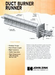
Change of plan. The team originally planned to<br />
modify the duplicate burner to enable fuelinduced<br />
recirculation. However, four factors<br />
were identified that changed the initial NO xreduction<br />
approach:<br />
� First, despite best efforts to simulate<br />
the furnace’s operating conditions<br />
and fuel gas, baseline testing showed<br />
the maximum NO x <strong>emissions</strong> generated<br />
in the test furnace were about 90<br />
ppm, compared with 160 ppm to 180<br />
ppm actually generated in the No. 4<br />
crude unit. Due to the difference<br />
between the test-furnace and crudeunit<br />
baseline <strong>emissions</strong>, there was<br />
concern that the test furnace goal should be lowered<br />
between 10 ppm and 12 ppm NO x to ensure less than<br />
20 ppm in the field application.<br />
� Second, although it was believed that an 80% to 90%<br />
reduction could be achieved with fuel-induced recirculation,<br />
a 95% reduction to 10 ppm that did not affect furnace<br />
performance was considered unlikely.<br />
� Third, because crude unit No. 4 had experienced overheating<br />
of the convection section, the team believed that<br />
raising the flue-gas flow through the section could<br />
increase coking in the convection section tubes.<br />
� Fourth, low-NO x <strong>emissions</strong> were being achieved with<br />
burners developed for radiant-wall furnaces. This factor<br />
changed the project’s initial NO x-reduction approach.<br />
Radiant-wall burners are used to heat high-temperature,<br />
wall-fired reformers and ethylene furnaces. Recent success<br />
in achieving low-NO x <strong>emissions</strong> with new radiant-wall burners,<br />
which use a combination of lean premix and “quasiflameless”<br />
combustion, led the burner engineers to explore<br />
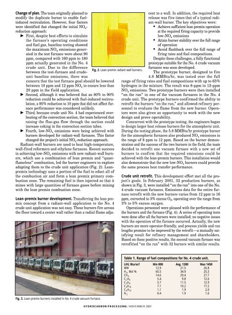
adapting them to the crude unit application (Fig. 2). Leanpremix<br />
technology uses a portion of the fuel to educt all of<br />
the combustion air and form a lean premix primary combustion<br />
zone. The remaining fuel is then injected so that it<br />
mixes with large quantities of furnace gases before mixing<br />
with the lean premix combustion zone.<br />
Lean-premix burner development. Transferring the lean premix<br />
concept from a radiant-wall application to the No. 4<br />
crude unit application was not easy. These burners fire across<br />
the floor toward a center wall rather than a radial flame adja-<br />
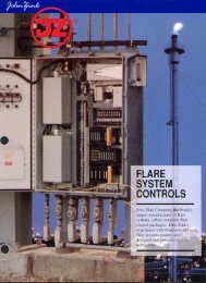
Fig. 3. Lean-premix burners installed in No. 4 crude vacuum furnace.<br />
Fig. 2. Lean-premix radiant wall burners.<br />
HYDROCARBON PROCESSING / NOVEMBER 2001<br />
cent to a wall. In addition, the required heat<br />
release was five times that of a typical radiant-wall<br />
burner. The key objectives were:<br />
• Achieve sufficient lean premix operation<br />
at the required firing capacity to provide<br />
low-NO x <strong>emissions</strong><br />
• Attain burner stability over the full range<br />
of operation<br />
• Avoid flashback over the full range of<br />
firing rates and fuel compositions.<br />
Despite these challenges, a fully functional<br />
prototype suitable for the No. 4 crude vacuum<br />
furnaces was soon developed.<br />
The prototype burner, designed to fire<br />
4.8 MMBtu/hr, was tested over the full<br />
range of firing rates and fuel compositions with up to 65%<br />
hydrogen in the mixture. The result was 8-ppm to 12-ppm<br />
NO x <strong>emissions</strong>. Two prototype burners were then installed<br />
“on the run” in one of the vacuum furnaces in the No. 4<br />
crude unit. The prototype burners confirmed the ability to<br />
retrofit the burners “on the run,” and allowed <strong>refinery</strong> personnel<br />
to evaluate the flame from the new burner. Operators<br />
were also given an opportunity to work with the new<br />
design and prove operability.<br />
Concurrent with the prototype testing, the engineers began<br />
to design larger heat release burners for the atmospheric unit.<br />
During the testing phase, the 5.8 MMBtu/hr prototype burner<br />
for the atmospheric furnaces also produced NO x <strong>emissions</strong> in<br />
the range of 8 ppm to 12 ppm. Based on the burner demonstration<br />
and the success of the two burners in the field, the team<br />
decided to retrofit one vacuum furnace with a new set of<br />
burners to confirm that the required <strong>emissions</strong> could be<br />
achieved with the lean-premix burners. This installation would<br />
also demonstrate that the new low-NO x burners could provide<br />
the same process heat transfer performance.<br />
Crude unit retrofit. This development effort met all the project’s<br />
goals. In February 2001, 32 production burners, as<br />
shown in Fig. 3, were installed “on the run” into one of the No.<br />
4 crude vacuum furnaces. Emissions data for the entire furnace<br />
retrofit with the new burners varies from 12 ppm to 16<br />
ppm, corrected to 3% excess O 2, operating over the range from<br />
3% to 5% excess oxygen.<br />
Operations personnel were pleased with the performance of<br />
the burners and the furnace (Fig. 4). A series of operating tests<br />
were done after all the burners were installed; no negative issues<br />
with the operation of the furnace occurred. Actually, the new<br />
burners are more operator-friendly, and process yields and run<br />
lengths promise to be improved by the retrofit—a mutually satisfying<br />
result for <strong>refinery</strong> management and shareholders.<br />
Based on these positive results, the second vacuum furnace was<br />
retrofitted “on the run” with 32 burners with similar results.<br />
Table 1. Range of fuel compositions for No. 4 crude unit.<br />
LHV, Btu/scf Min 800 Avg. 1200 Max 1450<br />
MW 12.9 21.5 26.8<br />
H 2, Mol % 65.5 34.9 25.3<br />
CH 4 14.6 29.4 27.7<br />
C 2H 6 5.4 9.8 12.6<br />
C 3H 8 5.7 11.5 12.9<br />
C 4H 10 7.1 10.2 17.2<br />
C 5H 12 1.1 1.9 2.0<br />
N 2 0.4 1.9 1.6