Control refinery NOx emissions cost-effectively - John Zink Company
Control refinery NOx emissions cost-effectively - John Zink Company
Control refinery NOx emissions cost-effectively - John Zink Company

Create successful ePaper yourself
Turn your PDF publications into a flip-book with our unique Google optimized e-Paper software.
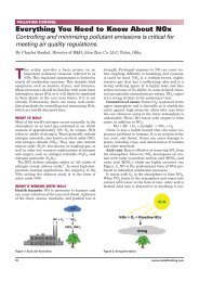
Refining Developments<br />
<strong>Control</strong> <strong>refinery</strong> NO x <strong>emissions</strong><br />
<strong>cost</strong>-<strong>effectively</strong><br />
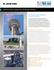
Refiner uses new ultra low-NO x burner technology<br />
to control emission levels from major sources<br />
J. G. Seebold, Chevron Corp., San Francisco, California;<br />
and R. T. Waibel and T. L. Webster, <strong>John</strong> <strong>Zink</strong> Co. LLC.,<br />
Tulsa, Oklahoma<br />
The California Clean Air Act limits ozone-causing<br />
<strong>emissions</strong> [nitrogen oxides (<strong>NOx</strong>) and volatile<br />
organic compounds (VOCs)] from existing furnaces<br />
and boilers and requires <strong>refinery</strong> owners to implement best<br />
available control technology (BACT). One <strong>refinery</strong> located<br />
in the San Francisco Bay area needed to reduce its daily<br />
average <strong>NOx</strong> <strong>emissions</strong> to less than 0.033-lb <strong>NOx</strong>/MMBtu fuel burned, equivalent to about 27-ppm <strong>NOx</strong>, corrected<br />
to 3% O2. A baseline survey revealed that three<br />
major fired systems—the crude heaters,<br />
power boilers and hydrogen reformers—produced<br />
more than 50% of the<br />
<strong>refinery</strong>’s total <strong>NOx</strong> <strong>emissions</strong>. The<br />
<strong>refinery</strong> researched methods to lower<br />
<strong>NOx</strong> from these major sources and<br />
reduce the plant-wide <strong>emissions</strong> average.<br />
This reduction would have the<br />
potential to bring the entire plant into<br />
compliance.<br />
The <strong>refinery</strong> owners understood<br />
that the operating conditions, furnace<br />
design, fuel supplies and other mitigating<br />
factors presented a challenge to<br />
providing a <strong>cost</strong>-effective, long-term<br />
solution that complied with BACT<br />
requirements. A problem-solving<br />
team, composed of <strong>refinery</strong> personnel,<br />
an engineering consultant and burner<br />
experts, was assembled. They evaluated,<br />
recommended and implemented<br />
<strong>NOx</strong>-reduction technologies that<br />
would allow the <strong>refinery</strong> to achieve its<br />
compliance goals in a timely and <strong>cost</strong>effective<br />
manner, while avoiding the<br />
<strong>cost</strong> and complexity of back-end<br />
cleanup systems. For the participants,<br />
the resulting burner development project,<br />
which addressed a challenge common<br />
to many refineries, produced a unique synergy not<br />
usually experienced.<br />
CRUDE HEATER SOLUTION<br />
The challenge. This <strong>refinery</strong> needed to reduce NO x <strong>emissions</strong><br />
from its No. 4 crude unit from 180 ppm to less than 20<br />
ppm. The crude unit has a combined firing rate of over one<br />
billion Btu/hr. To meet local NO x emission standards, support<br />
the <strong>refinery</strong>’s overall compliance plan and avoid installing<br />
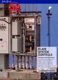
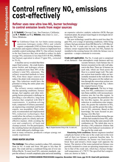
Fig. 1. Original burners firing in No. 4 crude unit.<br />
an expensive selective catalytic reduction (SCR) flue-gas<br />
treatment plant, the project team began to investigate developing<br />
low-NO x burner.<br />
The new technology would be able to emit less than 20ppm<br />
NO x over a range of operating conditions, while firing<br />
<strong>refinery</strong> fuel-gas mixtures from 800 Btu/scf to 1,450 Btu/scf.<br />
Since the No. 4 crude unit is the key operating unit, the<br />
<strong>refinery</strong> owner required that the new low-NO x burners be<br />
installed in the existing burner tile while the furnace was in<br />
operation—a major constraint to overcome.<br />
Crude-unit application. The No. 4 crude unit is comprised<br />
of six furnaces—four atmospheric crude furnaces and two<br />
vacuum furnaces. Each furnace has 32<br />
burners mounted on the side wall adjacent<br />
to the floor. There are 16 burners on<br />
each side, which are fired across the<br />
floor to a central target wall. The radiant<br />
section heat-transfer tubes are horizontally<br />
mounted on the wall above the<br />
burners. Flue gases exit the radiant section<br />
through the convection section centered<br />
above the target wall. Fig. 1 shows<br />
the original burners firing.<br />
Initial approach. The key to longterm,<br />
low-<strong>NOx</strong> combustion is to maintain<br />
flame stability with increased penetration<br />
into the low-Btu regime. In<br />
essence, the greater the penetration into<br />
the low-Btu regime, the greater the<br />
reduction in combustion-zone temperature,<br />
the greater the reduction in <strong>NOx</strong> reaction rate, and the greater the reduction<br />
in <strong>NOx</strong> <strong>emissions</strong>. Based on this<br />
knowledge, the team focused on producing<br />
a low-Btu fuel.<br />
Research showed that mixing flue gas<br />
with the fuel resulted in lower <strong>NOx</strong> <strong>emissions</strong><br />
than mixing the same amount with<br />
combustion air. The initial plan was to<br />
develop a <strong>NOx</strong>-reduction solution that<br />
involved fuel-induced recirculation of<br />
flue gas for the crude unit.<br />
Simulating field conditions. Burner engineers installed<br />
a duplicate burner of the one in the crude unit in the west<br />
wall of their test furnace to generate baseline data. To<br />
simulate field conditions, the burner was fired across a<br />
brick floor and toward a brick target wall opposite the<br />
burner. The interior of the water-jacketed test furnace was<br />
partially insulated to create an operating temperature similar<br />
to that of the crude unit, which has a furnace bridgewall<br />
temperature of 1,750°F. The specified fuel compositions<br />
are shown in Table 1.<br />
Reprinted from HYDROCARBON PROCESSING magazine, November 2001 issue, pgs 55-59. Used with permission.
Change of plan. The team originally planned to<br />
modify the duplicate burner to enable fuelinduced<br />
recirculation. However, four factors<br />
were identified that changed the initial NO xreduction<br />
approach:<br />
� First, despite best efforts to simulate<br />
the furnace’s operating conditions<br />
and fuel gas, baseline testing showed<br />
the maximum NO x <strong>emissions</strong> generated<br />
in the test furnace were about 90<br />
ppm, compared with 160 ppm to 180<br />
ppm actually generated in the No. 4<br />
crude unit. Due to the difference<br />
between the test-furnace and crudeunit<br />
baseline <strong>emissions</strong>, there was<br />
concern that the test furnace goal should be lowered<br />
between 10 ppm and 12 ppm NO x to ensure less than<br />
20 ppm in the field application.<br />
� Second, although it was believed that an 80% to 90%<br />
reduction could be achieved with fuel-induced recirculation,<br />
a 95% reduction to 10 ppm that did not affect furnace<br />
performance was considered unlikely.<br />
� Third, because crude unit No. 4 had experienced overheating<br />
of the convection section, the team believed that<br />
raising the flue-gas flow through the section could<br />
increase coking in the convection section tubes.<br />
� Fourth, low-NO x <strong>emissions</strong> were being achieved with<br />
burners developed for radiant-wall furnaces. This factor<br />
changed the project’s initial NO x-reduction approach.<br />
Radiant-wall burners are used to heat high-temperature,<br />
wall-fired reformers and ethylene furnaces. Recent success<br />
in achieving low-NO x <strong>emissions</strong> with new radiant-wall burners,<br />
which use a combination of lean premix and “quasiflameless”<br />
combustion, led the burner engineers to explore<br />
adapting them to the crude unit application (Fig. 2). Leanpremix<br />
technology uses a portion of the fuel to educt all of<br />
the combustion air and form a lean premix primary combustion<br />
zone. The remaining fuel is then injected so that it<br />
mixes with large quantities of furnace gases before mixing<br />
with the lean premix combustion zone.<br />
Lean-premix burner development. Transferring the lean premix<br />
concept from a radiant-wall application to the No. 4<br />
crude unit application was not easy. These burners fire across<br />
the floor toward a center wall rather than a radial flame adja-<br />
Fig. 3. Lean-premix burners installed in No. 4 crude vacuum furnace.<br />
Fig. 2. Lean-premix radiant wall burners.<br />
HYDROCARBON PROCESSING / NOVEMBER 2001<br />
cent to a wall. In addition, the required heat<br />
release was five times that of a typical radiant-wall<br />
burner. The key objectives were:<br />
• Achieve sufficient lean premix operation<br />
at the required firing capacity to provide<br />
low-NO x <strong>emissions</strong><br />
• Attain burner stability over the full range<br />
of operation<br />
• Avoid flashback over the full range of<br />
firing rates and fuel compositions.<br />
Despite these challenges, a fully functional<br />
prototype suitable for the No. 4 crude vacuum<br />
furnaces was soon developed.<br />
The prototype burner, designed to fire<br />
4.8 MMBtu/hr, was tested over the full<br />
range of firing rates and fuel compositions with up to 65%<br />
hydrogen in the mixture. The result was 8-ppm to 12-ppm<br />
NO x <strong>emissions</strong>. Two prototype burners were then installed<br />
“on the run” in one of the vacuum furnaces in the No. 4<br />
crude unit. The prototype burners confirmed the ability to<br />
retrofit the burners “on the run,” and allowed <strong>refinery</strong> personnel<br />
to evaluate the flame from the new burner. Operators<br />
were also given an opportunity to work with the new<br />
design and prove operability.<br />
Concurrent with the prototype testing, the engineers began<br />
to design larger heat release burners for the atmospheric unit.<br />
During the testing phase, the 5.8 MMBtu/hr prototype burner<br />
for the atmospheric furnaces also produced NO x <strong>emissions</strong> in<br />
the range of 8 ppm to 12 ppm. Based on the burner demonstration<br />
and the success of the two burners in the field, the team<br />
decided to retrofit one vacuum furnace with a new set of<br />
burners to confirm that the required <strong>emissions</strong> could be<br />
achieved with the lean-premix burners. This installation would<br />
also demonstrate that the new low-NO x burners could provide<br />
the same process heat transfer performance.<br />
Crude unit retrofit. This development effort met all the project’s<br />
goals. In February 2001, 32 production burners, as<br />
shown in Fig. 3, were installed “on the run” into one of the No.<br />
4 crude vacuum furnaces. Emissions data for the entire furnace<br />
retrofit with the new burners varies from 12 ppm to 16<br />
ppm, corrected to 3% excess O 2, operating over the range from<br />
3% to 5% excess oxygen.<br />
Operations personnel were pleased with the performance of<br />
the burners and the furnace (Fig. 4). A series of operating tests<br />
were done after all the burners were installed; no negative issues<br />
with the operation of the furnace occurred. Actually, the new<br />
burners are more operator-friendly, and process yields and run<br />
lengths promise to be improved by the retrofit—a mutually satisfying<br />
result for <strong>refinery</strong> management and shareholders.<br />
Based on these positive results, the second vacuum furnace was<br />
retrofitted “on the run” with 32 burners with similar results.<br />
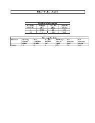
Table 1. Range of fuel compositions for No. 4 crude unit.<br />
LHV, Btu/scf Min 800 Avg. 1200 Max 1450<br />
MW 12.9 21.5 26.8<br />
H 2, Mol % 65.5 34.9 25.3<br />
CH 4 14.6 29.4 27.7<br />
C 2H 6 5.4 9.8 12.6<br />
C 3H 8 5.7 11.5 12.9<br />
C 4H 10 7.1 10.2 17.2<br />
C 5H 12 1.1 1.9 2.0<br />
N 2 0.4 1.9 1.6
The four atmospheric furnaces are also<br />
scheduled for “on the run” retrofit.<br />
POWER BOILER SOLUTION<br />
The challenge. A baseline survey indicated<br />
that five utility boilers in the<br />
<strong>refinery</strong>’s power plant No. 1 were contributing<br />
about 25% of the total <strong>refinery</strong><br />
NO x <strong>emissions</strong>, with observed<br />
levels ranging from 250 ppm to 450<br />
ppm. The power-boiler <strong>emissions</strong><br />
needed to be reduced 89% to 94% for<br />
the plant to meet the new daily average<br />
emission rate, which required less<br />
than 0.033-lb NO x /MMBtu fuel<br />
burned, equivalent to about 27-ppm<br />
NO x corrected to 3% O 2.<br />
Power-boiler application. Power plant<br />
No. 1 uses four D. B. Riley (Riley) watertube<br />
boilers (units 1, 3, 4 and 5) each<br />
rated at 140,000 lb/hr and one Babcock<br />
& Wilcox (B&W) water-tube boiler (unit<br />
7) rated at 180,000 lb/hr of 850-psig<br />
steam. Boilers No. 1 and 3 were built in<br />
1936, boilers No. 4 and 5 were built in<br />
1941, and boiler No. 7 was built in 1953.<br />
Each boiler was equipped with the original boiler manufacturers’<br />
burners. They operated on <strong>refinery</strong> gas fuel with<br />
approximately 25% hydrogen by volume, and had combustion<br />
air preheat levels between 400ºF and 500ºF. Each Riley<br />
boiler used five burners each with rated capacities of 40<br />
MMBtu/hr; the B&W boiler used four burners each with a<br />
capacity rating of 70 MMBtu/hr.<br />
Initial approach. Due to the combination of <strong>refinery</strong> fuel<br />
burned, level of air preheat and design of the old boilers, it<br />
was determined that new off-the-shelf burners could not be<br />
considered as replacements without requiring significant<br />
and <strong>cost</strong>ly modifications to the existing combustion-air system.<br />
Moreover, an initial study recommended that the plant<br />
Fig. 5. Five low-NO x burners installed in power boiler.<br />
Fig. 4. Lean-premix burners firing in No. 4 crude<br />
furnace.<br />
HYDROCARBON PROCESSING / NOVEMBER 2001<br />
install two SCR systems behind the<br />
boiler house.<br />
To install the SCR equipment, the<br />
<strong>refinery</strong> would have to alter the hill<br />
behind the boiler house to provide<br />
enough space to install the SCRs. Installation<br />
would also involve redirecting<br />
the exhaust from all five boilers to the<br />
remote-located SCR systems using a<br />
fan with more than 2,500 hp and a complicated<br />
duct network.<br />
The <strong>refinery</strong> identified a capital <strong>cost</strong><br />
of more than $20 million for the SCRs,<br />
and an increase in annual operating<br />
<strong>cost</strong>s by as much as $1.5 million. In<br />
addition, using ammonia posed a risk<br />
of leaks or “slip” into the atmosphere,<br />
and of creating harmful air <strong>emissions</strong>.<br />
Consequently, the plant decided to<br />
search out alternate low-emission combustion<br />
technologies.<br />
Combustion technology selection. The<br />
<strong>refinery</strong>’s engineering consultant evaluated<br />
a number of low-NO x options and<br />
recommended the <strong>refinery</strong> commission<br />
the development of new burners using<br />
fuel-dilution technology rather than using<br />
a conventional flue gas recirculation (FGR) strategy.<br />
Fuel-dilution technology, which was successfully implemented<br />
at the <strong>refinery</strong> owner’s other locations, involves a<br />
process whereby boiler flue gases are induced and mixed<br />
with existing <strong>refinery</strong> gas fuel to generate a low-BTU gas. Fuel<br />
dilution is more effective in reducing NO x than conventional<br />
FGR. Therefore, it requires less flue gas for the same amount<br />
of NO x reduction and has a much lower impact to the boiler<br />
operation. Fuel-dilution technology uses the motive force of<br />
the fuel rather than fans to transport the flue gases, thus lowering<br />
operations <strong>cost</strong>s. Because the plant wanted to reuse the<br />
existing combustion air fans, which had limited capacities,<br />
inducing large volumes of flue gas was not an option. Therefore,<br />
the fuel-dilution technology presented a means to add flue<br />
Fig. 6. NO x <strong>emissions</strong> after retrofit, the new low-NO x burners in boiler No. 4.<br />
Note: Unit maintained NO x ratings below 27 ppm corrected to 3% O 2.
Fig. 7. NO x results at various steam additions—25 lb and 46 lb.<br />
gas without modifying, replacing or adding fans. Previous successful<br />
conversions and comparison results of fuel dilution vs.<br />
FGR, concluded that developing a new low-NO x burner using<br />
fuel-dilution technology was the best strategy to meet the<br />
latest California regulations.<br />
Burner development. Because the <strong>refinery</strong>’s co-generation<br />
plant and other steam producers yield excess steam, the No. 5<br />
Riley boiler was available and provided an ideal situation for<br />
prototype testing. The engineering consultant designed, fabricated<br />
and installed five prototype fuel-dilution burners that<br />
used multiple gas nozzles and available fuel pressure to induce<br />
flue gases from an integral flue gas plenum.<br />
The system design included fuel-dilution burners, ducting<br />
to transport the flue gases from the stack to the prototype<br />
burners, a small amount of induced FGR supplied to the<br />
existing fan, and a steam-injection sparger in the fuel-dilution<br />
line. To provide optimum safety and reliability, a new<br />
burner management system was also installed. The only<br />
design restriction involved the original burner openings in<br />
the windbox and boiler front wall, which needed to remain<br />
unaltered so that the original burners could be reinstalled<br />
should the experiments fail. After installing and optimizing<br />
the system, the prototype burners and steam-sparging system<br />
consistently produced NO x levels of 15 ppm to 20 ppm,<br />
corrected to 3% O 2.<br />
Production burner supply. The results of the prototype testing<br />
on boiler No. 5 clearly indicated that fuel-dilution technology<br />
was a viable solution. A burner company with fueldilution<br />
experience was commissioned to retrofit the<br />
remaining boilers.<br />
Based on the initial prototypes, the burner engineers worked<br />
closely with the <strong>refinery</strong> team and engineering consultant to<br />
finalize the new, low-NO x design, supply production burners<br />
to retrofit the four remaining boilers, and to replace the prototypes<br />
on boiler No. 5. The burner engineers also performed<br />
an air-distribution study of the windboxes and combustion air<br />
systems using in-house physical modeling technology to<br />
ensure balanced airflow and optimum burner performance of<br />
each unit. Based on the modeling results, baffles were added<br />
to the windboxes to balance airflow for stable flame formation<br />
without combustion-induced boiler vibration and to minimize<br />
excess air levels and boiler <strong>emissions</strong>.<br />
Realizing that any recycling of flue gases would increase<br />
mass flow through the boiler, thus increasing convective section<br />
velocities and superheat temperatures, the lengths of<br />
convection section baffles above and below the superheat<br />
tubes were modified in all boilers except No. 7. This unit historically<br />
had lower steam superheat temperatures than the<br />
HYDROCARBON PROCESSING / NOVEMBER 2001<br />
maximum design superheater outlet temperature, resulting<br />
in the superheat temperature staying within the operating<br />
limits of the boiler.<br />
Power-boiler retrofit results. Low-NO x burner installation on<br />
the four remaining boilers began in February 2000 and was completed<br />
by mid-July 2000 (Fig. 5). The prototype burners on boiler<br />
No. 5 were also replaced with low-NO x burners in May 2001.<br />
All the retrofitted boilers operate on a 24/7 basis and consistently<br />
maintain NO x <strong>emissions</strong> at or below 25 ppm, corrected<br />
to 3% O 2 (Fig. 6.)<br />
The boilers can achieve single digit NO x ratings with additional<br />
sparging of low-pressure steam, if available, with almost<br />
no additional operating expense (Fig. 7). Since this plant has<br />
to let down 850-psig steam for sparging, which can result in<br />
a considerable ongoing operating expense, the <strong>refinery</strong> wanted<br />
to control the steam-injection rate to the amount required for<br />
the boilers to stay below their permitted NO x levels. Therefore,<br />
James G. Seebold has more than 35 years experience<br />
consulting with Chevron’s operating centers and affiliated<br />
companies worldwide on all aspects of the design,<br />
operation and maintenance of burners, fired-heaters, furnaces,<br />
incinerators, boilers and flares. His area of expertise<br />
also includes: low-NO x burners, selective catalytic<br />
and noncatalytic NO x reduction systems, hazardous air<br />
pollutant <strong>emissions</strong>, onshore plant, offshore platform<br />
and shipboard noise control engineering. He currently<br />
serves as his company’s main contact person for the<br />
International Flame Research Foundation and as director of the Noise <strong>Control</strong><br />
Foundation. Past positions include technical advisor for the DOE Study of Oxygen<br />
Enriched Combustion, technical advisor for the EPA Study of Industrial Flares<br />
and president for the Institute of Noise <strong>Control</strong> Engineering. Dr. Seebold conceived<br />
and led the American Petroleum Institute’s Detonation Arrester Testing<br />
Program for applications in fired marine-vapor disposal systems. He conceived<br />
and led a 4-year, $7-million, 20-participant industry-government-university<br />
collaboration on trace combustion byproducts that led to successful public<br />
policy intervention on Combustion MACT. Dr. Seebold holds a doctorate degree<br />
in mechanical engineering from Stanford University.<br />
Richard T. Waibel is director of engineering and<br />
design for the combustion technology team in the <strong>John</strong><br />
<strong>Zink</strong> Co., burner group. Dr. Waibel has been with the<br />
<strong>John</strong> <strong>Zink</strong> Co. since 1983. He is a graduate of Pennsylvania<br />
State University, with a BS and Ph.D. degrees<br />
in fuel science. He and his team are responsible for providing<br />
customers with innovative burner designs and<br />
combustion solutions. Prior to joining <strong>John</strong> <strong>Zink</strong>, Dr.<br />
Waibel was assistant director of Industrial Energy Utilization<br />
at the Institute of Gas Technology in Chicago.<br />
He is a member of The Combustion Institute and has been a member of the American<br />
Flame Research Committee and the International Flame Research Foundation.<br />
He has been chairman of the American Flame Research Committee since<br />
1995. Dr. Waibel has authored numerous industry papers—many of which can<br />
be accessed at www.johnzink.com. He is also a contributing author of The<br />
<strong>John</strong> <strong>Zink</strong> Combustion Handbook.<br />
Timothy L. Webster is the director of marketing for the<br />
TODD Combustion Group of <strong>John</strong> <strong>Zink</strong> Co., LLC. He joined<br />
<strong>John</strong> <strong>Zink</strong> in August of 1999 as the product line manager<br />
for the TODD Rapid Mix Burner (RMB). Mr. Webster quickly<br />
expanded his role to act as manager for new technologies.<br />
In 2001, Mr. Webster moved into his current role heading<br />
up TODD’s marketing efforts and focusing on new opportunities<br />
for business and product development. He has<br />
authored papers on several combustion topics, including<br />
biomass combustion, ultra-low emission burners, gas-fuel<br />
conditioning, combustion modeling and other NO x reduction techniques for boilers,<br />
many of which can be accessed at www.<strong>John</strong><strong>Zink</strong>.com. He was also one of<br />
the contributing authors of The <strong>John</strong> <strong>Zink</strong> Combustion Handbook. Mr. Webster<br />
received a BS degree in mechanical engineering from San Jose State University<br />
and an MS degree from the University of Wisconsin. He is also a licensed professional<br />
mechanical engineer.
the team implemented a fuel-gas cascade control scheme to<br />
eliminate operator adjustment of steam-injection rates as<br />
boiler-firing rates vary.<br />
HYDROGEN REFORMER SOLUTION<br />
Lastly, to bring the entire plant into compliance, the team<br />
analyzed the <strong>emissions</strong> levels and performance of the hydrogen<br />
reformers. Upon reviewing baseline data of the terrace<br />
wall-fired hydrogen reformer furnace, the team set out to<br />
apply a solution similar to the one implemented on the crude<br />
unit. Presently, prototype testing at the burner engineers’ test<br />
furnace has achieved NO x ratings of 10 ppm to 12 ppm.<br />
Based on the successful prototype tests, the <strong>refinery</strong> elected<br />
to procure and proceed with manufacture of the production<br />
burners. The team plans to install the production burners in<br />
the first quarter of 2002.<br />
TOTAL PLANT SOLUTION.<br />
The result of the cooperative efforts among <strong>refinery</strong> personnel,<br />
the engineering consultant and burner experts was an<br />
innovative and <strong>cost</strong>-effective solution to tough <strong>emissions</strong><br />
LK/1M/12-01 Article copyright © 2001 by Gulf Publishing Co.<br />
reduction applications. Development efforts met all the project’s<br />
goals, providing more than 90% NO x reduction while<br />
maintaining safe, reliable combustion performance.<br />
Specifically, the new low-NO x burners for the crude unit performed<br />
at design conditions while reducing NO x <strong>emissions</strong> 85%<br />
to 95%. This installation used the existing burner tiles and<br />
required no heater modifications. The “on the run” installation<br />
also required zero crude-unit downtime. Finally, the low-NO x<br />
crude-unit burners eliminated the need for an SCR, saving the<br />
<strong>refinery</strong> $10 million in capital <strong>cost</strong>s and $2 million in annual<br />
operating <strong>cost</strong>s.<br />
Further, successful application of fuel-dilution technology<br />
on all five boilers resulted in more than 90% NO x reduction,<br />
allowing all the boilers to meet the targeted limit while experiencing<br />
substantial <strong>cost</strong> savings. The boiler-burner retrofit also<br />
eliminated the need for two SCR systems, saving the <strong>refinery</strong><br />
$7 million in capital <strong>cost</strong>s and $1.5 million in annual operating<br />
<strong>cost</strong>s. Also with additional steam sparging, the burners are<br />
capable of reaching ultra-low-NO x levels of less than 7 ppm.<br />
The team expects the projected hydrogen reformer retrofit to<br />
achieve a 90% NO x reduction. �<br />
®