

O Scale Trains Magazine Online
O Scale Trains Magazine Online
O Scale Trains Magazine Online
- TAGS
- trains
- oscalemag.com

You also want an ePaper? Increase the reach of your titles
YUMPU automatically turns print PDFs into web optimized ePapers that Google loves.
the track power to the turntable. It has<br />
two short insulated sections that allow the<br />
polarity of the turntable to be switched at<br />
each 180 degrees of rotation. The circle<br />
of N <strong>Scale</strong> track provides power to the<br />
lights on the turntable.<br />
The square driving post also has a 1/8”<br />
center hole for the center alignment pin.<br />
It is attached to the drive disc with two<br />
woodscrews. The sides of the post were<br />
carefully sanded to allow a close fit into<br />
the turntable. We’ll see more on that<br />
later.<br />
The disc has routed slots that hold<br />
the wires feeding the two track circles.<br />
The wires exit the top of the disc against<br />
opposing flat sides of the drive post. This<br />
insures that they will clear the center hole<br />
of the pit as the post rotates. Miniature<br />
connectors provide quick electrical connections<br />
to the turntable.<br />
Three-rail locomotive pickups provide<br />
the voltage transfer to the power tracks.<br />
The voltage pickups for the N <strong>Scale</strong> track<br />
are installed 180 degrees apart. They are<br />
mounted on brass strips.<br />
The two pickups for the turntable<br />
power are mounted in one cutout. This<br />
is due to the short length of the two insulated<br />
sections of the track circle. Their<br />
mounting brackets were made from 3/8”<br />
square styrene tubing.<br />
The motor is a Pittman gear-head<br />
motor with a 19.5:1 speed reduction. The<br />
motor mounting bracket is a piece of 3/4”<br />
plywood drilled to fit the body of the<br />
motor. The bracket was then cut down so<br />
the hole was open on one side. A metal<br />
strip is used as the motor clamp. A rubber<br />
bushing on the motor shaft provides<br />
the friction-drive transfer to the cork drive<br />
ring on the disc. Since the output shaft<br />
of the motor is off-center, rotating the<br />
motor in the mounting bracket adjusts the<br />
load of the bushing on the drive ring. The<br />
weight of the drive disc helps maintain<br />
this friction coupling.<br />
The photo above shows the drive disc<br />
installed into the drive box. Masking tape<br />
was added over the wire slots on the disc<br />
to hold the wires in place. The drive disc<br />
is shown rotated with the insulated sec-<br />
tions of the HO power track positioned<br />
over the power pickups. Positioning the<br />
drive block at this location will orient the<br />
turntable at approximately 90 degrees to<br />
the inbound track. This will be the point<br />
of rotation at which the turntable track<br />
polarity will be reversed. The drywall<br />
screws located around the drive disc add<br />
extra support to the top panel of the drive<br />
box,<br />
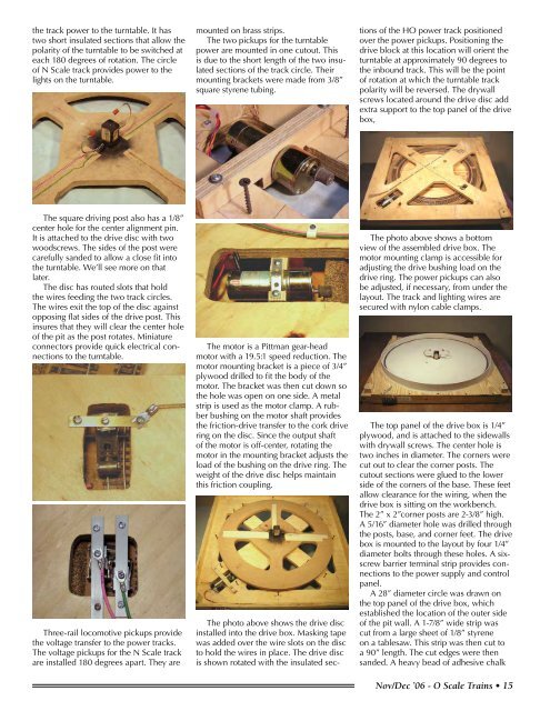
The photo above shows a bottom<br />
view of the assembled drive box. The<br />
motor mounting clamp is accessible for<br />
adjusting the drive bushing load on the<br />
drive ring. The power pickups can also<br />
be adjusted, if necessary, from under the<br />
layout. The track and lighting wires are<br />
secured with nylon cable clamps.<br />
The top panel of the drive box is 1/4”<br />
plywood, and is attached to the sidewalls<br />
with drywall screws. The center hole is<br />
two inches in diameter. The corners were<br />
cut out to clear the corner posts. The<br />
cutout sections were glued to the lower<br />
side of the corners of the base. These feet<br />
allow clearance for the wiring, when the<br />
drive box is sitting on the workbench.<br />
The 2” x 2”corner posts are 2-3/8” high.<br />
A 5/16” diameter hole was drilled through<br />
the posts, base, and corner feet. The drive<br />
box is mounted to the layout by four 1/4”<br />
diameter bolts through these holes. A sixscrew<br />
barrier terminal strip provides connections<br />
to the power supply and control<br />
panel.<br />
A 28” diameter circle was drawn on<br />
the top panel of the drive box, which<br />
established the location of the outer side<br />
of the pit wall. A 1-7/8” wide strip was<br />
cut from a large sheet of 1/8” styrene<br />
on a tablesaw. This strip was then cut to<br />
a 90” length. The cut edges were then<br />
sanded. A heavy bead of adhesive chalk<br />
Nov/Dec ’06 - O <strong>Scale</strong> <strong>Trains</strong> • 1


