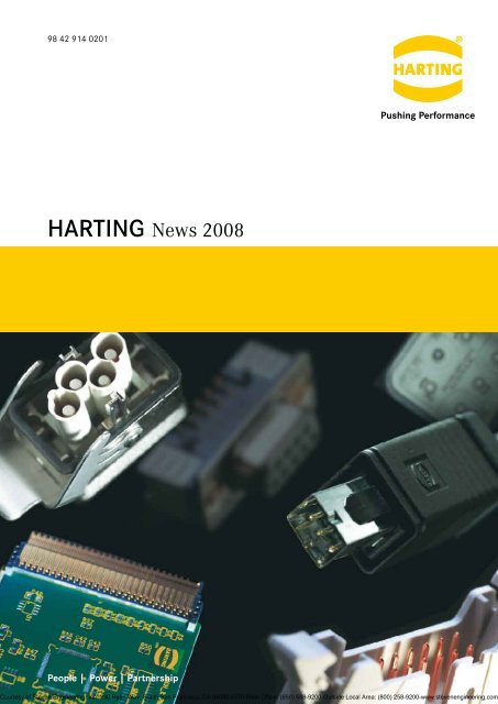
Harting Product News 2008 - Steven Engineering
Harting Product News 2008 - Steven Engineering
Harting Product News 2008 - Steven Engineering

Create successful ePaper yourself
Turn your PDF publications into a flip-book with our unique Google optimized e-Paper software.
98 42 914 0201<br />
HARTING<br />
People | Power | Partnership<br />
<strong>News</strong> <strong>2008</strong><br />
Courtesy of <strong>Steven</strong> <strong>Engineering</strong>, Inc.-230 Ryan Way, South San Francisco, CA 94080-6370-Main Office: (650) 588-9200-Outside Local Area: (800) 258-9200-www.stevenengineering.com
Quality Connections<br />
Worldwide<br />
HARTING was founded in 1945 by the<br />
family that still owns the company.<br />
Its headquarters are situated in<br />
Espelkamp, in Eastern Westphalia.<br />
Today, HARTING employs approximate<br />
3,000 people worldwide, including<br />
300 engineers and scientists. Over<br />
500 technical specialists are available<br />
to implement customer requirements.<br />
With subsidiaries in 27 countries and<br />
ten production plants, the company is<br />
one of the leading manufacturers of<br />
electrical and electronic connectors.<br />
The global HARTING network means<br />
that the company is always in close<br />
touch with the market and ideally placed<br />
to work together with its customers.<br />
As the market leader HARTING offers<br />
the benefits of just-in-time service and<br />
maintains close business relations with<br />
all of its key customers in the global<br />
marketplace. In more than one of its<br />
product areas, HARTING leads the field.<br />
HARTING products are manufactured<br />
using advanced, automated techniques,<br />
with CAD systems employed both<br />
in research and development and<br />
in tool-making.<br />
In matters of quality, HARTING is<br />
convinced that zero-defect production<br />
can only be achieved through fully<br />
automated processes. Our quality<br />
assurance organization and procedures<br />
are documented in accordance with<br />
EN ISO 9001 in a quality assurance<br />
manual. In 2006 HARTING became<br />
the first company worldwide to receive<br />
the new IRIS quality certificate<br />
(the International Railway Industry<br />
Standard).<br />
HARTING employs around 60 staff<br />
in quality assurance alone.<br />
The majority of these engineers and<br />
technicians are trained and qualified<br />
to standards laid down by the<br />
DGQ (German Association of Quality)<br />
or SAQ (Swiss Association of Quality).<br />
Courtesy of <strong>Steven</strong> <strong>Engineering</strong>, Inc.-230 Ryan Way, South San Francisco, CA 94080-6370-Main Office: (650) 588-9200-Outside Local Area: (800) 258-9200-www.stevenengineering.com
HARTING <strong>News</strong><br />
Contents Seite<br />
Industrial Connectors<br />
Han ® 4 A Quick Lock . . . . . . . . . . . . . . . . . . . . . . . . . . . . . . . . . . . . . 6<br />
Han ® Q 5/0 Quick Lock . . . . . . . . . . . . . . . . . . . . . . . . . . . . . . . . . . . . 7<br />
Han-Modular ® EE Module Quick Lock . . . . . . . . . . . . . . . . . . . . . . . . . 8<br />
Han ® Q 12/0 . . . . . . . . . . . . . . . . . . . . . . . . . . . . . . . . . . . . . . . . . . . . 10<br />
Han-Modular ® Compact M25 und M32 . . . . . . . . . . . . . . . . . . . . . . . . 12<br />
Han-Elisa ® . . . . . . . . . . . . . . . . . . . . . . . . . . . . . . . . . . . . . . . . . . . . . . 14<br />
Han-Power ® T Modular Twin . . . . . . . . . . . . . . . . . . . . . . . . . . . . . . . . 18<br />
Han ® 3 A Hood with integrated Cable Gland . . . . . . . . . . . . . . . . . . . 19<br />
Han-INOX ® 3 A . . . . . . . . . . . . . . . . . . . . . . . . . . . . . . . . . . . . . . . . . . 20<br />
Han ® A Gasket . . . . . . . . . . . . . . . . . . . . . . . . . . . . . . . . . . . . . . . . . . . 21<br />
Han ® 16 HPR Bulkhead mounted Housing with Cover . . . . . . . . . . . . 22<br />
Han ® Q 4/2 Inserts with PCB adapter . . . . . . . . . . . . . . . . . . . . . . . . . 24<br />
Han ® Q 8/0 Inserts with PCB adapter . . . . . . . . . . . . . . . . . . . . . . . . . 26<br />
Han ® PushPull<br />
Han ® PushPull Power 4/0 Metal . . . . . . . . . . . . . . . . . . . . . . . . . 28<br />
Han ® PushPull Power 4/0 Plastic . . . . . . . . . . . . . . . . . . . . . . . . 30<br />
Han ® PushPull RJ45 Metal . . . . . . . . . . . . . . . . . . . . . . . . . . . . . 32<br />
Han ® PushPull RJ45 Plastic . . . . . . . . . . . . . . . . . . . . . . . . . . . . 34<br />
Han ® PushPull SCRJ Metal . . . . . . . . . . . . . . . . . . . . . . . . . . . . . 36<br />
Han ® PushPull SCRJ Plastic . . . . . . . . . . . . . . . . . . . . . . . . . . . . 37<br />
HARAX ® . . . . . . . . . . . . . . . . . . . . . . . . . . . . . . . . . . . . . . . . . . . . . . . . 38<br />
HARAX ® M8-S<br />
HARAX ® M8-S (0 .8 mm²)<br />
HARAX ® M12-S<br />
HARAX ® M12-L Profibus<br />
HARAX ® M12 with HARAX ® IDC<br />
HARAX ® M12 with Crimp terminal<br />
Industrial Ethernet<br />
HARTING eCon 2000 . . . . . . . . . . . . . . . . . . . . . . . . . . . . . . . . . . . . . 42<br />
HARTING eCon 2050-AA . . . . . . . . . . . . . . . . . . . . . . . . . . . . . . 45<br />
HARTING eCon 2160-A . . . . . . . . . . . . . . . . . . . . . . . . . . . . . . . 46<br />
HARTING eCon 3000 Media converter . . . . . . . . . . . . . . . . . . . . . . . . 47<br />
HARTING eCon 3011-AD . . . . . . . . . . . . . . . . . . . . . . . . . . . . . . 50<br />
HARTING eCon 3011-ASFP . . . . . . . . . . . . . . . . . . . . . . . . . . . . 51<br />
Courtesy of <strong>Steven</strong> <strong>Engineering</strong>, Inc.-230 Ryan Way, South San Francisco, CA 94080-6370-Main Office: (650) 588-9200-Outside Local Area: (800) 258-9200-www.stevenengineering.com
HARTING <strong>News</strong><br />
Contents Seite<br />
HARTING sCon Introduction . . . . . . . . . . . . . . . . . . . . . . . . . . . . . . . . 52<br />
HARTING sCon 3000 . . . . . . . . . . . . . . . . . . . . . . . . . . . . . . . . . . . . . 53<br />
HARTING sCon 3061-AE . . . . . . . . . . . . . . . . . . . . . . . . . . . . . . 56<br />
HARTING sCon 3063-AE . . . . . . . . . . . . . . . . . . . . . . . . . . . . . . 57<br />
HARTING sCon 3082-AE . . . . . . . . . . . . . . . . . . . . . . . . . . . . . . 58<br />
HARTING sCon 3061-AF . . . . . . . . . . . . . . . . . . . . . . . . . . . . . . 59<br />
HARTING sCon 3082-AF . . . . . . . . . . . . . . . . . . . . . . . . . . . . . . 60<br />
HARTING mCon 3000 . . . . . . . . . . . . . . . . . . . . . . . . . . . . . . . . . . . . . 61<br />
HARTING mCon 3061-AE . . . . . . . . . . . . . . . . . . . . . . . . . . . . . . 65<br />
HARTING mCon 3063-AE . . . . . . . . . . . . . . . . . . . . . . . . . . . . . . 66<br />
HARTING mCon 3082-AE . . . . . . . . . . . . . . . . . . . . . . . . . . . . . . 67<br />
HARTING mCon 1000 . . . . . . . . . . . . . . . . . . . . . . . . . . . . . . . . . . . . . 68<br />
HARTING mCon 1052-AE . . . . . . . . . . . . . . . . . . . . . . . . . . . . . . 72<br />
HARTING mCon 1052-AE . . . . . . . . . . . . . . . . . . . . . . . . . . . . . . 73<br />
HARTING mCon 1061-AE . . . . . . . . . . . . . . . . . . . . . . . . . . . . . . 74<br />
HARTING mCon 1070-AE . . . . . . . . . . . . . . . . . . . . . . . . . . . . . . 75<br />
HARTING mCon 1082-AE . . . . . . . . . . . . . . . . . . . . . . . . . . . . . . 76<br />
HARTING mCon 1083-AE . . . . . . . . . . . . . . . . . . . . . . . . . . . . . . 77<br />
Accessories mCon 1000 . . . . . . . . . . . . . . . . . . . . . . . . . . . . . . . 78<br />
HARTING pCon 2000 . . . . . . . . . . . . . . . . . . . . . . . . . . . . . . . . . . . . . 80<br />
HARTING pCon 2035-24 . . . . . . . . . . . . . . . . . . . . . . . . . . . . . . . 81<br />
HARTING pCon 2060-24 . . . . . . . . . . . . . . . . . . . . . . . . . . . . . . . 82<br />
HARTING pCon 2060-48 . . . . . . . . . . . . . . . . . . . . . . . . . . . . . . . 83<br />
HARTING pCon 2120-24 . . . . . . . . . . . . . . . . . . . . . . . . . . . . . . . 84<br />
System cable Cat . 6 PVC . . . . . . . . . . . . . . . . . . . . . . . . . . . . . . . . . . 85<br />
System cable Cat . 6 PUR . . . . . . . . . . . . . . . . . . . . . . . . . . . . . . . . . . 86<br />
System cable Cat . 6 Outdoor . . . . . . . . . . . . . . . . . . . . . . . . . . . . . . . . 87<br />
Installation cable Cat . 6A . . . . . . . . . . . . . . . . . . . . . . . . . . . . . . . . . . . 88<br />
System cable Cat . 5 PUR . . . . . . . . . . . . . . . . . . . . . . . . . . . . . . . . . . 89<br />
System cable with HARTING RJ Industrial ® on both sides . . . . . . . . . 90<br />
System cable with HARTING PushPull on both sides . . . . . . . . . . . . . 91<br />
System cable with HARTING PushPull to RJ45 (IP 20) . . . . . . . . . . . . 92<br />
System cable with Han ® 3 A to RJ45 (IP 20) . . . . . . . . . . . . . . . . . . . . 93<br />
System cable with Han ® PushPull on both sides . . . . . . . . . . . . . . . . . 94<br />
Additional information about overmoulded system cables . . . . . . . . . . 95<br />
HARTING PushPull Hybrid . . . . . . . . . . . . . . . . . . . . . . . . . . . . . . . . . 97<br />
Device side . . . . . . . . . . . . . . . . . . . . . . . . . . . . . . . . . . . . . . . . . 98<br />
Connector . . . . . . . . . . . . . . . . . . . . . . . . . . . . . . . . . . . . . . . . . . 99<br />
System cable, overmoulded . . . . . . . . . . . . . . . . . . . . . . . . . . . . 100<br />
Courtesy of <strong>Steven</strong> <strong>Engineering</strong>, Inc.-230 Ryan Way, South San Francisco, CA 94080-6370-Main Office: (650) 588-9200-Outside Local Area: (800) 258-9200-www.stevenengineering.com
HARTING <strong>News</strong><br />
Contents Page<br />
Electronic Connectors<br />
D-Sub SMT board connectors . . . . . . . . . . . . . . . . . . . . . . . . . . . . . . . 101<br />
D-Sub filter adapter . . . . . . . . . . . . . . . . . . . . . . . . . . . . . . . . . . . . . . . 106<br />
har-link ® connectors and cable assemblies . . . . . . . . . . . . . . . . . . . . . 108<br />
SEK male headers with straight press-in pins . . . . . . . . . . . . . . . . . . 111<br />
SEK pcb transition connectors, 2 rows . . . . . . . . . . . . . . . . . . . . . . . . 114<br />
SEK female cable connectors . . . . . . . . . . . . . . . . . . . . . . . . . . . . . . . 116<br />
SEK male headers with straight solder pins, kinked . . . . . . . . . . . . . . 119<br />
TCA connectors<br />
General information . . . . . . . . . . . . . . . . . . . . . . . . . . . . . . . . . . 122<br />
. . . . . . . . . . . . . . . . . . . . . . . . . . . . . . . . . . . . . . . . 124<br />
AdvancedMC connectors for AdvancedTCA ® . . . . . . . . . . . . . 126<br />
Power connectors for AdvancedTCA ® . . . . . . . . . . . . . . . . . . . . 128<br />
AdvancedMC connector for MicroTCA . . . . . . . . . . . . . . . . 130<br />
Power output connectors for MicroTCA . . . . . . . . . . . . . . . . . 132<br />
Plug connectors for MicroTCA and AdvancedTCA . . . . . . . 135<br />
Press-in tooling . . . . . . . . . . . . . . . . . . . . . . . . . . . . . . . . . . . . . . 140<br />
Signal integrity support . . . . . . . . . . . . . . . . . . . . . . . . . . . . . . . . 142<br />
Summary Catalogues . . . . . . . . . . . . . . . . . . . . . . . . . . . . . . . . . . . . . . . . . 144<br />
Addresses . . . . . . . . . . . . . . . . . . . . . . . . . . . . . . . . . . . . . . . . . . . . . . . . . . 145<br />
Courtesy of <strong>Steven</strong> <strong>Engineering</strong>, Inc.-230 Ryan Way, South San Francisco, CA 94080-6370-Main Office: (650) 588-9200-Outside Local Area: (800) 258-9200-www.stevenengineering.com
Han ® 4 A Quick Lock<br />
Features<br />
• Innovative Han-Quick Lock ® termination<br />
technology<br />
• Field assembly without special tools<br />
• Compatible to Han ® 4 A standard<br />
inserts<br />
• Reduced wiring times<br />
• Insert suitable for all metal and plastic<br />
hoods and housings of the sizes Han ® 3 A<br />
• Vibration resistant<br />
Han ® 4 A Quick Lock<br />
09 20 004 2633<br />
09 20 004 2733<br />
Han-Quick Lock ®<br />
Technical characteristics<br />
Protection degree IP 65 / IP 67<br />
Number of contacts 4 + PE<br />
Electrical data acc . to<br />
DIN EN 61 984 10 A 230/400 V 4 kV 3<br />
Rated current 10 A<br />
Rated voltage conductor-ground 230 V<br />
Rated voltage conductor-conductor 400 V<br />
Rated impulse voltage 4 kV<br />
Pollution degree 3<br />
Termination Han-Quick Lock ®<br />
Wire gauge 0 .5 bis 2 .5 mm² (AWG 20–14)<br />
Insulation resistance ≥ 10 10 Ω<br />
Material Polycarbonate<br />
Flammability acc . to UL 94 V 0<br />
Mechanical working life ≥ 500 mating cycles<br />
Identification Part-Number Drawing Dimensions in mm<br />
Male insert<br />
Female insert<br />
Courtesy of <strong>Steven</strong> <strong>Engineering</strong>, Inc.-230 Ryan Way, South San Francisco, CA 94080-6370-Main Office: (650) 588-9200-Outside Local Area: (800) 258-9200-www.stevenengineering.com
Han ® Q 5/0 Quick Lock<br />
Features<br />
• Innovative Han-Quick Lock ® termination<br />
technology<br />
• Field assembly without special tools<br />
• Compatible with Han ® Q 5/0 standard<br />
inserts<br />
• Reduced wiring times<br />
• Insert suitable for all metal and plastic<br />
hoods and housings of the sizes Han ® 3 A<br />
• Vibration resistant<br />
09 12 005 2633<br />
09 12 005 2733<br />
Han-Quick Lock ®<br />
Technical characteristics<br />
Identification Part-Number Drawing Dimensions in mm<br />
Han ® Q 5/0 Quick Lock<br />
Male insert<br />
Female insert<br />
Protection degree IP 65 / IP 67<br />
Number of contacts 5 + PE<br />
Electrical data acc . to<br />
DIN EN 61 984 16 A 230/400 V 4 kV 3<br />
Rated current 16 A<br />
Rated voltage conductor-ground 230 V<br />
Rated voltage conductor-conductor 400 V<br />
Rated impulse voltage 4 kV<br />
Pollution degree 3<br />
Termination Han-Quick Lock ®<br />
Wire gauge 0 .5 bis 2 .5 mm² (AWG 20–14)<br />
Insulation resistance ≥ 10 10 Ω<br />
Material Polycarbonate<br />
Flammability acc . to UL 94 V 0<br />
Mechanical working life ≥ 500 mating cycles<br />
Courtesy of <strong>Steven</strong> <strong>Engineering</strong>, Inc.-230 Ryan Way, South San Francisco, CA 94080-6370-Main Office: (650) 588-9200-Outside Local Area: (800) 258-9200-www.stevenengineering.com
Han ® EE Module Quick Lock<br />
Samples available<br />
by November <strong>2008</strong><br />
Features<br />
• Innovative Han-Quick Lock ® termination<br />
technology<br />
• Field assembly without special tools<br />
• Compatible to standard Han ® EE<br />
module with crimp termination<br />
• Reduced wiring times<br />
09 14 008 2633<br />
09 14 008 2733<br />
Han-Quick Lock ®<br />
Technical characteristics<br />
Bezeichnung Bestell-Nummer Zeichnung Maße in mm<br />
Han ® EE module Quick Lock<br />
Male insert<br />
Female insert<br />
Number of contacts 8<br />
Electrical data acc . to<br />
DIN EN 61 984 16 A 400 V 6 kV 3<br />
Rated current 16 A<br />
Rated voltage 400 V<br />
Rated impulse voltage 6 kV<br />
Pollution degree 3<br />
Termination Han-Quick Lock ®<br />
Wire gauge 0 .5 bis 2 .5 mm² (AWG 20–14)<br />
Insulation resistance ≥ 10 10 Ω<br />
Material Polycarbonate<br />
Flammability acc . to UL 94 V 0<br />
Mechanical working life ≥ 500 mating cycles<br />
Courtesy of <strong>Steven</strong> <strong>Engineering</strong>, Inc.-230 Ryan Way, South San Francisco, CA 94080-6370-Main Office: (650) 588-9200-Outside Local Area: (800) 258-9200-www.stevenengineering.com
Notes<br />
Courtesy of <strong>Steven</strong> <strong>Engineering</strong>, Inc.-230 Ryan Way, South San Francisco, CA 94080-6370-Main Office: (650) 588-9200-Outside Local Area: (800) 258-9200-www.stevenengineering.com
10<br />
Han ® Q 12/0<br />
Number of contacts<br />
12 +<br />
Inserts<br />
Han D ® crimp contacts<br />
silver plated<br />
09 12 012 3001<br />
09 12 012 3101<br />
09 12 000 9924 09 12 000 9924<br />
09 15 000 6104<br />
09 15 000 6103<br />
09 15 000 6105<br />
09 15 000 6102<br />
09 15 000 6101<br />
09 15 000 6106<br />
09 15 000 6124<br />
09 15 000 6123<br />
09 15 000 6125<br />
09 15 000 6122<br />
09 15 000 6121<br />
09 15 000 6126<br />
09 15 000 6204<br />
09 15 000 6203<br />
09 15 000 6205<br />
09 15 000 6202<br />
09 15 000 6201<br />
09 15 000 6206<br />
09 15 000 6224<br />
09 15 000 6223<br />
09 15 000 6225<br />
09 15 000 6222<br />
09 15 000 6221<br />
09 15 000 6226<br />
Han-Quick Lock ®<br />
Part Number<br />
Identification Male insert Female insert Dimensions in mm<br />
Han ® Q 12/0<br />
Coding pins<br />
order separately<br />
1 unit à 20 pieces<br />
Wire gauge Part Number<br />
Identification mm² Male contacts Female contacts Dimensions in mm<br />
gold plated<br />
0.14-0.37<br />
0 .5<br />
0 .75<br />
1 .0<br />
1 .5<br />
2 .5<br />
0.14-0.37<br />
0 .5<br />
0 .75<br />
1 .0<br />
1 .5<br />
2 .5<br />
0.14-0.37 mm²<br />
0 .5 mm²<br />
0 .75 mm²<br />
1 .0 mm²<br />
1 .5 mm²<br />
2 .5 mm²<br />
Wire gauge ø Stripping<br />
length<br />
AWG 26-22<br />
AWG 20<br />
AWG 18<br />
AWG 18<br />
AWG 16<br />
AWG 14<br />
0 .90 mm<br />
1 .10 mm<br />
1 .30 mm<br />
1 .45 mm<br />
1 .75 mm<br />
2 .25 mm<br />
Courtesy of <strong>Steven</strong> <strong>Engineering</strong>, Inc.-230 Ryan Way, South San Francisco, CA 94080-6370-Main Office: (650) 588-9200-Outside Local Area: (800) 258-9200-www.stevenengineering.com<br />
8 mm<br />
8 mm<br />
8 mm<br />
8 mm<br />
8 mm<br />
6 mm
Han ® Q 12/0<br />
Features Technical characteristics<br />
• 12 contact chambers taking the control contacts<br />
of the series Han D ® with crimp termination<br />
• 1 PE contact with innovative Han-Quick Lock ®<br />
termination technology<br />
• 2 coding pins offering 16 coding possibilities<br />
• Insert suitable for metal and plastic hoods and<br />
housings of the series Han ® 3 A<br />
Specifications<br />
Inserts<br />
DIN VDE 0627<br />
DIN VDE 0110<br />
DIN EN 61 984<br />
Number of contacts<br />
Electrical data acc . to<br />
12 + PE<br />
DIN EN 61 984 10 A 400 V 6 kV 3<br />
Rated current 10 A<br />
Rated voltage 400 V<br />
Rated impulse voltage 4 kV<br />
Pollution degree 3<br />
Pollution degree 2 also 10 A 400/690 V 6 kV 2<br />
Termination Han D ® contacts Crimp<br />
Termination PE contact Han-Quick Lock ®<br />
Wire gauge PE contact 0 .5 – 2 .5 mm²<br />
AWG 20 – 14<br />
Insulation resistance ≥ 10 10 Ω<br />
Material Polycarbonate<br />
Limiting temperatures -40 °C . . . +125 °C<br />
Flammability acc . to UL 94 V 0<br />
Mechanical working life ≥ 500 mating cycles<br />
Contacts<br />
Material Copper alloy<br />
Surface<br />
- hard silver plated 3 µm Ag<br />
- hard gold plated 2 µm Au over 3 µm Ni<br />
Contact resistance ≤ 3 mΩ<br />
Crimp termination<br />
- mm² 0 .14 – 2 .5 mm²<br />
- AWG 26 – 14<br />
Maximum insilation cross section<br />
- power contacts ø = 5 mm<br />
Plastic hoods/ housings<br />
Material Polycarbonate<br />
Locking element Polyamide<br />
Flammability acc . to UL 94 V 0<br />
Hoods/ housings seal NBR<br />
Limiting temperatures -40 °C . . . +125 °C<br />
Degree of protection acc . to<br />
DIN EN 60 529 in locked position IP 67<br />
Metal hoods/ housings<br />
Material Die cast zinc alloy<br />
Locking element Steel galvanized<br />
Hoods/ housings seal NBR<br />
Limiting temperatures -40 °C . . . +125 °C<br />
Degree of protection acc . to<br />
DIN EN 60 529 in locked position IP 44<br />
IP 67 with sealing screw<br />
09 20 000 9918<br />
Courtesy of <strong>Steven</strong> <strong>Engineering</strong>, Inc.-230 Ryan Way, South San Francisco, CA 94080-6370-Main Office: (650) 588-9200-Outside Local Area: (800) 258-9200-www.stevenengineering.com<br />
11
12<br />
Han-Modular ® Compact<br />
*Available by May <strong>2008</strong><br />
Hoods and housings M25 and M32<br />
Identification Part number Drawing Dimensions in mm<br />
Hood<br />
side entry M25<br />
Hood<br />
top entry M25<br />
Hood*<br />
top entry M32<br />
screws are added<br />
separately<br />
Carrier hood<br />
Protection cover<br />
with lever and seal<br />
Housing<br />
bulkhead mounting<br />
Protection cover<br />
19 14 01 0501<br />
19 14 001 0401<br />
19 14 001 0402<br />
09 14 001 0311<br />
09 14 001 5402<br />
09 14 001 0301<br />
09 14 001 5401<br />
4 screws are<br />
included in<br />
delivery range<br />
4 screws are<br />
included in<br />
delivery range<br />
4 screws are<br />
included in<br />
delivery range<br />
Panel cut out<br />
Courtesy of <strong>Steven</strong> <strong>Engineering</strong>, Inc.-230 Ryan Way, South San Francisco, CA 94080-6370-Main Office: (650) 588-9200-Outside Local Area: (800) 258-9200-www.stevenengineering.com
Han-Modular ® Compact<br />
Features Technical characteristics<br />
• Compact design saves space<br />
• Modular structure increases flexibility<br />
• Simple and quick assembly<br />
• Robust design<br />
• Two part grommet housing<br />
➀ Hood with side entry<br />
➁ Thread M25<br />
➂ Bulkhead mounted housing with locking lever<br />
➃ Carrier hood<br />
Hoods/Housings<br />
Material Zinc die-cast<br />
Surface Nickel plated<br />
Locking element Stainless steel<br />
Hoods/housings sealing NBR<br />
Limiting temperatures -40 °C ... 125 °C<br />
Degree of protection acc . to<br />
DIN EN 60 529<br />
for coupled connectors IP 65<br />
Mechanical working life ≥ 500 mating cycles<br />
PE contact<br />
Wire gauge 10 mm² / 8 AWG<br />
Stripping length 10 mm<br />
Tightening torque 1 Nm<br />
Protection covers<br />
Material Polycarbonate<br />
Locking element Polyamide<br />
Hoods/housings sealing NBR<br />
Limiting temperatures -40 °C ... 125 °C<br />
Degree of protection acc . to<br />
DIN EN 60 529<br />
for coupled connectors IP 65<br />
Flammability acc . to UL 94 V 0<br />
Current carrying capacity<br />
The current carrying capacity of the connectors is limited by<br />
the thermal load capability of the contact element material including<br />
the connections and the insulating parts . The derating<br />
curve is therefore valid for currents which flow constantly (nonintermittent)<br />
through each contact element of the connector<br />
evenly, without exceeding the allowed maximum temperature .<br />
Measuring and testing techniques acc . to DIN EN 60 512-5<br />
Working current [A]<br />
Ambient temperature [C]<br />
1 = Han ® Axial screw module, Wire gauge: 10 mm²<br />
2 = Han ® C module, Wire gauge: 6 mm²<br />
Courtesy of <strong>Steven</strong> <strong>Engineering</strong>, Inc.-230 Ryan Way, South San Francisco, CA 94080-6370-Main Office: (650) 588-9200-Outside Local Area: (800) 258-9200-www.stevenengineering.com<br />
1
1<br />
Han-Elisa ®<br />
Flexibles I/O system<br />
integrated inside the connector<br />
Features General description<br />
• Signal pre-processing and conversion do fit into<br />
the connector<br />
• Individual combination of input and output<br />
modules for optimal signal pre-processing<br />
• Minimum size for integration in Han ® industrial<br />
connectors (Han-Modular ® and Han-Snap ® )<br />
• Economy of space by reduction the number of<br />
terminal blocks and interface modules in the<br />
switch cabinet<br />
The Han-Elisa ® modules are a flexible I/O system<br />
- directly in the connector .<br />
The In- and Output modules are developed for 1<br />
or 2 channels and can be combined variously and<br />
flexible for optimal signal pre-processing. Within<br />
the product family modules are available for<br />
current/voltage conversion, temperature, relay and<br />
timer .<br />
Due to the minimized size these modules can be<br />
integrated into the Han-Modular ® and Han-Snap ®<br />
system .<br />
Signal pre-processing and conversion do fit into the<br />
connector and this will reduce installation space<br />
for terminal blocks and the number of interface<br />
modules . So the switch cabinets can be made<br />
smaller .<br />
Courtesy of <strong>Steven</strong> <strong>Engineering</strong>, Inc.-230 Ryan Way, South San Francisco, CA 94080-6370-Main Office: (650) 588-9200-Outside Local Area: (800) 258-9200-www.stevenengineering.com
Han-Elisa Ethernet Switch SmartCon<br />
®<br />
General Technische technical Kennwerte characteristics<br />
Environmental conditions<br />
Operation -20 °C . . . +65 °C<br />
Storage -40 °C . . . +85 °C<br />
Mechanical data<br />
Dimensions (WxDxH) 30 .3 x 53 x 14 .7 mm<br />
Material Polycarbonate / LCP<br />
Mating face • Input module: male<br />
• Output module: female<br />
Degree of protection acc . to DIN 60 529 • IP 20<br />
• IP 65 within mated connector<br />
(e .g . Han ® B housing, high construction)<br />
Cage clamp terminal 0 .14 - 1 .5 mm²<br />
Power supply (combination input and output module)<br />
Supply voltage 24 V (-10% . . . +25%)<br />
Current consumption < 0 .08 A<br />
Power consumption < 2 W<br />
Total transmission error < 0 .2 %<br />
<strong>Product</strong> matrix and possible combinations of Han-Elisa ® modules<br />
Input<br />
modules<br />
Output<br />
modules<br />
Relay<br />
Different version<br />
Optocoupler<br />
Different versions<br />
Timing X X<br />
Connecting 1:1 X X<br />
Temperature<br />
Pt100<br />
Different<br />
temperature ranges<br />
Temperature<br />
thermo element<br />
type J, K<br />
Different<br />
temperature ranges<br />
Input<br />
current 4 . . . 20 mA<br />
Input<br />
voltage 0 . . . 10 V<br />
X = on request<br />
● = available<br />
Output<br />
current<br />
4 . . . 20 mA<br />
galvanically isolated<br />
Output<br />
voltage<br />
0 . . . 10 V<br />
galvanically isolated<br />
● ●<br />
X X<br />
X X<br />
X X<br />
Courtesy of <strong>Steven</strong> <strong>Engineering</strong>, Inc.-230 Ryan Way, South San Francisco, CA 94080-6370-Main Office: (650) 588-9200-Outside Local Area: (800) 258-9200-www.stevenengineering.com<br />
1
16<br />
Han-Elisa ®<br />
Available by August <strong>2008</strong><br />
Pt100 Input module<br />
Features<br />
• Minimum size for integration in Han ® industrial<br />
connectors (Han-Modular ® and Han-Snap ® )<br />
• Economy of space by reduction the number of<br />
terminal blocks and interface modules in the<br />
switch cabinet<br />
• Male module for signal output<br />
Temperature module<br />
Pt100<br />
20 75 108 1001<br />
20 75 108 1003<br />
Technical characteristics<br />
Sensor Pt100 acc. to IEC 751<br />
Termination technology 2, 3, 4 wire technology<br />
Sensor input current 0.8 mA, constant<br />
Max. permissible conductor resistance 10 Ω per conductor<br />
Min. measuring range 100 °C<br />
Open circuit detection integrated<br />
Type of connection<br />
- cage clamp termination 0.14 - 1.5 mm²<br />
Power diagnostic LED (green)<br />
Identification Part number Drawing Dimensions in mm<br />
Measuring range:<br />
0 ... 100 °C<br />
0 ... 200 °C<br />
additional measuring ranges<br />
on request<br />
Courtesy of <strong>Steven</strong> <strong>Engineering</strong>, Inc.-230 Ryan Way, South San Francisco, CA 94080-6370-Main Office: (650) 588-9200-Outside Local Area: (800) 258-9200-www.stevenengineering.com<br />
Input
Han-Elisa ®<br />
Available by August <strong>2008</strong><br />
Output module<br />
Features<br />
• Minimum size for integration in Han ® industrial<br />
connectors (Han-Modular ® and Han-Snap ® )<br />
• Economy of space by reduction the number of<br />
terminal blocks and interface modules in the<br />
switch cabinet<br />
• Female module for signal input<br />
Output module, current<br />
3-ways-isolating amplifier<br />
galvanically isolated<br />
20 75 104 2201<br />
20 75 105 2201<br />
Supply voltage 24 V DC (-10 % ... +25 %)<br />
Load Iout < 500 Ω<br />
Load Uout ≥ 10 kΩ<br />
Residual ripple < 20 mV (500 Ω)<br />
Step response (0 ... 99 %)<br />
Type of connection<br />
< 30 ms<br />
- cage clamp termination 0.14 - 1.5 mm²<br />
Power diagnostic LED (green)<br />
Identification Part number Drawing Dimensions in mm<br />
Output signal<br />
4 ... 20 mA<br />
Output module, voltage<br />
3-ways-isolating amplifier<br />
galvanically isolated<br />
Additional output signals<br />
on request<br />
Output signal<br />
0 ... 10 V<br />
Technical characteristics<br />
Output<br />
Output<br />
Courtesy of <strong>Steven</strong> <strong>Engineering</strong>, Inc.-230 Ryan Way, South San Francisco, CA 94080-6370-Main Office: (650) 588-9200-Outside Local Area: (800) 258-9200-www.stevenengineering.com<br />
17
1<br />
Han-Power ® T Modular Twin<br />
Samples available<br />
by September <strong>2008</strong><br />
with Han-Modular ® Twin<br />
Part-Number: 09 12 008 4760<br />
Features Han-Power ® T<br />
• 1 connection for power input and output each<br />
• 1 T-connection to device<br />
• 3 power contacts<br />
• 5 signal contacts<br />
• Metal hood<br />
• Locking lever Han-Easy Lock ®<br />
Han-Modular ® Twin Hoods<br />
Dimensions in mm<br />
Technical characteristics<br />
Han-Power ® T Modular Twin hood<br />
Rated voltage 400 V<br />
Rated current 40 A<br />
Number of contacts 3 power contacts + PE<br />
max . 6 mm²<br />
5 signal contacts<br />
max . 2 .5 mm²<br />
Surface powder coated RAL 7037<br />
Sealing NBR<br />
Temperature range -40 °C . . . +125 °C<br />
Protection degree<br />
acc . to DIN 60 529 IP 65<br />
Suitable inserts<br />
Han ® C module with crimp termination<br />
Number of contacts 3<br />
Rated current<br />
Rated voltage<br />
40 A<br />
Conductor - Ground 400 V<br />
Conductor - Conductor 690 V<br />
Rated impulse voltage 6 kV<br />
Pollution degree 3<br />
Han ® ES module with cage clamp termination<br />
Number of contacts 5<br />
Rated current 16 A<br />
Rated voltage 400 V<br />
Rated impulse voltage 6 kV<br />
Pollution degree 3<br />
Material Polycarbonate<br />
Insulation resistance ≥ 10 10 Ω<br />
Temperature range -40 °C . . . +125 °C<br />
Flammability acc . to UL 94 V 0<br />
Mechanical working life ≥ mating cycles<br />
For more Han-Modular ® inserts see chapter 6 in the main<br />
catalogue of HARTING Electric GmbH & Co . KG<br />
Courtesy of <strong>Steven</strong> <strong>Engineering</strong>, Inc.-230 Ryan Way, South San Francisco, CA 94080-6370-Main Office: (650) 588-9200-Outside Local Area: (800) 258-9200-www.stevenengineering.com
Han ® 3 A Hood with integrated Cable gland<br />
Features<br />
• Installation height reduced by 25 % compared<br />
with existing standard solutions<br />
• Large clamping range of 6 –17 mm<br />
• Reduction of logistic complexitiy by integration<br />
of cable gland<br />
Without glued sealing<br />
Clamping range<br />
6 - 12 mm<br />
11 - 17 mm<br />
For small cable diameter<br />
Pull identification tab outwards or remove<br />
19 20 003 1421<br />
19 20 003 1422<br />
19 20 003 1425<br />
Technical characteristics<br />
Material Zinc die-cast<br />
Surface Powder-coated<br />
RAL 7037 ( grey)<br />
Cable gland Brass, nickel-plated<br />
with high quality rubber sealing<br />
element<br />
Clamping range 6 - 17 mm<br />
Limiting temperatures -40 °C . . . 125 °C<br />
Degree of protection<br />
accd . to EN 60 529<br />
in locked position IP 44<br />
IP 67 with use of sealing screw<br />
09 20 000 9918<br />
Identification Part Number Drawing Dimensions in mm<br />
With glued sealing<br />
Clamping range<br />
6 - 12 mm<br />
Assembly instructions<br />
For large cable diameter<br />
Remove blue insert: place the screw driver vertically into<br />
the separation seam and lift out the blue insert<br />
Courtesy of <strong>Steven</strong> <strong>Engineering</strong>, Inc.-230 Ryan Way, South San Francisco, CA 94080-6370-Main Office: (650) 588-9200-Outside Local Area: (800) 258-9200-www.stevenengineering.com<br />
1
20<br />
Han-INOX ®<br />
Available by June <strong>2008</strong><br />
Stainless steel hoods and housings<br />
Features Technical characteristics<br />
• Hoods and housings as well as locking elements<br />
out of stainless steel<br />
• Resistant against aggressive detergents<br />
• Fields of application<br />
- Food and beverage industry<br />
- Water and sewage industry<br />
- Pharmaceutical industry<br />
- Chemical industry<br />
- Offshore and shipbuilding<br />
• Available in the size 3 A<br />
• Suitable for all standard inserts that fit into sizes<br />
Han ® 3 A<br />
Hood Han ® 3 A<br />
top entry<br />
with glued sealing<br />
Bulkhead mounted housing<br />
Han ® 3 A<br />
with 1 metal locking lever<br />
19 44 003 1440<br />
19 44 003 1443<br />
19 44 003 0301<br />
20<br />
20<br />
_<br />
Material Stainless steel<br />
Sealing NBR<br />
Limiting temperatures -40 °C . . . +125 °C<br />
Protection degree<br />
in locked position IP 65<br />
Locking lever Stainless steel<br />
Identification Part-Number M Drawing Dimensions in mm<br />
Panel cut out<br />
22 x 22 mm<br />
Courtesy of <strong>Steven</strong> <strong>Engineering</strong>, Inc.-230 Ryan Way, South San Francisco, CA 94080-6370-Main Office: (650) 588-9200-Outside Local Area: (800) 258-9200-www.stevenengineering.com
Han ® A Gasket<br />
Han ® A standard hoods and housings with gasket<br />
Features<br />
• Is included in the delivery range<br />
• Smart handling<br />
• Fast panel mounting<br />
• Long life time<br />
• Suitable for rough environments<br />
• Avoid loosing panel mounting screws<br />
Han ® gasket size 10 A *<br />
Han ® gasket size 16 A *<br />
09 20 000 9998<br />
09 20 000 9999<br />
Technical characteristics<br />
Material NBR<br />
Surface black<br />
Limiting temperatures -40 °C . . . 125 °C<br />
Degree of protection<br />
acc . to EN 60 529 IP 65<br />
Identification Part Number Drawing Dimensions in mm<br />
* . . . only for the use in combination with bulk-<br />
head mounting housings including blind<br />
hole<br />
Size Length in mm<br />
a b c<br />
10 A 80 70 57<br />
16 A 96 86 73<br />
Courtesy of <strong>Steven</strong> <strong>Engineering</strong>, Inc.-230 Ryan Way, South San Francisco, CA 94080-6370-Main Office: (650) 588-9200-Outside Local Area: (800) 258-9200-www.stevenengineering.com<br />
21
22<br />
Han ® 16 HPR<br />
Bulkhead mounted housing with cover<br />
Features Technical characteristics<br />
• HPR cover cap included<br />
• Pressure tight design<br />
• Highly EMI resistant<br />
• Captive screws<br />
• Corrosion resistant<br />
Identification Part number Size Drawing Dimensions in mm<br />
Han ® 16 HPR<br />
bulkhead mounting<br />
with cover<br />
09 40 016 0317<br />
16 B<br />
Material Corrosion resistant die cast<br />
aluminium alloy<br />
Surface<br />
- Top Coat Epoxy powder paint (black)<br />
Limiting temperatures -40 °C . . . +85 °C<br />
Degree of protection<br />
acc . to DIN 60 529 IP 65<br />
Size B<br />
Panel cut out<br />
Courtesy of <strong>Steven</strong> <strong>Engineering</strong>, Inc.-230 Ryan Way, South San Francisco, CA 94080-6370-Main Office: (650) 588-9200-Outside Local Area: (800) 258-9200-www.stevenengineering.com
Notes<br />
Courtesy of <strong>Steven</strong> <strong>Engineering</strong>, Inc.-230 Ryan Way, South San Francisco, CA 94080-6370-Main Office: (650) 588-9200-Outside Local Area: (800) 258-9200-www.stevenengineering.com<br />
2
2<br />
Han ® Q 4/2 inserts with PCB adapter<br />
Features Technical characteristics<br />
• Robust Design<br />
• Suitable for Han-Compact ® hoods and housings<br />
• Low wiring costs<br />
• High contact density<br />
Layout of printed circuit boards<br />
Assembly details<br />
PCB<br />
PCB adapter<br />
Wall of cabinet<br />
Number of contacts 4/2 + PE<br />
Electrical data accd . to<br />
DIN EN 61 984<br />
Power area 30 A 400/690 V 6 kV 2<br />
Rated current 30 A<br />
Rated voltage<br />
conductor - ground 400 V<br />
conductor - conductor 690 V<br />
Rated impulse voltage 6 kV<br />
Pollution degree 2<br />
Signal area 7 .5 A 250 V 4 kV 2<br />
Rated current 7 .5 A<br />
Rated voltage 250 V<br />
Rated impulse voltage 4 kV<br />
Pollution degree 2<br />
Insulation resistance ≥ 10 10 Ω<br />
Material LCP<br />
Limiting temperatures -40 °C . . . +125 °C<br />
Flammability accd . to UL 94 V 0<br />
Mechanical working life ≥ 500 mating cycles<br />
Dimensions in mm<br />
Han-Compact ® bulkhead mounted housing<br />
Han ® Q 4/2 double contact<br />
Han ® Q 4/2 insert<br />
Dimensions in mm<br />
X = 16 +1 with signal contact<br />
16 +2 without signal contact<br />
Courtesy of <strong>Steven</strong> <strong>Engineering</strong>, Inc.-230 Ryan Way, South San Francisco, CA 94080-6370-Main Office: (650) 588-9200-Outside Local Area: (800) 258-9200-www.stevenengineering.com
Han ® Q 4/2 inserts with PCB adapter<br />
Part-Number<br />
Inserts Male insert (M) Female insert (F) Drawings Dimensions in mm<br />
order contacts separately<br />
to connect the PCB adapter<br />
power contact<br />
signal contact<br />
plastic<br />
09 12 006 3041 09 12 006 3141<br />
09 12 006 9901<br />
09 32 000 6180 09 32 000 6280<br />
09 15 000 6191 09 15 000 6293<br />
09 12 008 0327<br />
Contact arrangement<br />
view from termination side<br />
PCB adapter Part-Number Drawings Dimensions in mm<br />
for PCBs up to 2 .4 mm<br />
Han ® Part-Number<br />
Q 4/2 double contacts Male contact (M) Female contact (F) Drawings Dimensions in mm<br />
Housing bulkhead mounting Part-Number Drawings Dimensions in mm<br />
Mating connector<br />
Panel cut out<br />
crimp terminal see chapter 13 .21 in main catalogue 02 3<br />
Industral Connectors Han ®<br />
Courtesy of <strong>Steven</strong> <strong>Engineering</strong>, Inc.-230 Ryan Way, South San Francisco, CA 94080-6370-Main Office: (650) 588-9200-Outside Local Area: (800) 258-9200-www.stevenengineering.com<br />
2
2<br />
Han ® Q 8/0 inserts with PCB adapter 230/400 V 16 A<br />
Features<br />
• Robust Design<br />
• Suitable for Han-Compact ® hoods and housings<br />
• Low wiring costs<br />
• High contact density<br />
Layout of printed circuit boards<br />
Assembly details<br />
PCB<br />
PCB adapter<br />
Wall of cabinet<br />
Han-Compact ® bulkhead mounted housing<br />
Technical characteristics<br />
Number of contacts 8<br />
Electrical data accd . to<br />
DIN EN 61 984 16 A 230/400 V 4 kV 2<br />
Rated current 16 A<br />
Rated voltage<br />
conductor - ground 230 V<br />
conductor - conductor 400 V<br />
Rated impulse voltage 4 kV<br />
Pollution degree 2<br />
Insulation resistance ≥ 10 10 Ω<br />
Material Polycarbonate<br />
Limiting temperatures -40 °C . . . +125 °C<br />
Flammability accd . to UL 94 V 0<br />
Mechanical working life ≥ 500 mating cycles<br />
Han ® E double contact<br />
Han ® Q 8/0 insert<br />
Dimensions in mm<br />
Dimensions in mm<br />
Courtesy of <strong>Steven</strong> <strong>Engineering</strong>, Inc.-230 Ryan Way, South San Francisco, CA 94080-6370-Main Office: (650) 588-9200-Outside Local Area: (800) 258-9200-www.stevenengineering.com
Han ® Q 8/0 inserts with PCB adapter 230/400 V 16 A<br />
Part-Number<br />
Inserts Male insert (M) Female insert (F) Drawings Dimensions in mm<br />
order contacts separately<br />
09 12 008 3001 09 12 008 3101<br />
PCB adapter Part-Number Drawings Dimensions in mm<br />
for PCBs up to 1 .6 mm<br />
to connect the PCB adapter<br />
plastic<br />
Mating connector<br />
09 12 008 9901<br />
09 33 000 6180 09 33 000 6280<br />
09 12 008 0327<br />
Panel cut out<br />
Contact arrangement<br />
view from termination side<br />
Han E ® Part-Number<br />
double contacts Male contact (M) Female contact (F) Drawings Dimensions in mm<br />
Housing bulkhead mounting Part-Number Drawings Dimensions in mm<br />
crimp terminal see chapter 13 .17 in main catalogue 02 3<br />
Industral Connectors Han ®<br />
Courtesy of <strong>Steven</strong> <strong>Engineering</strong>, Inc.-230 Ryan Way, South San Francisco, CA 94080-6370-Main Office: (650) 588-9200-Outside Local Area: (800) 258-9200-www.stevenengineering.com<br />
2
2<br />
Han ® PushPull Power 4/0 Metal<br />
Features Technical characteristics<br />
• HARTING Push Pull Technology<br />
• Compact design<br />
• Finger protected<br />
• Cable side; female insert<br />
- crimp termination<br />
- fast termination technology Han-Quick Lock ®<br />
• Panel feed through<br />
- crimp termination<br />
- fast termination technology Han-Quick Lock ®<br />
- solder termination<br />
09 35 002 5401<br />
09 35 002 5412<br />
09 35 002 5411<br />
09 35 000 6103<br />
09 35 000 6104<br />
09 35 000 6105<br />
09 35 000 6106<br />
09 35 000 6107<br />
Number of contacts 4 + PE<br />
Electrical data acc . to<br />
DIN EN 61 984<br />
Rated current<br />
Rated voltage<br />
16 A<br />
- solder termination 230/400 V<br />
- crimp termination 690 V<br />
- Han-Quick Lock ® termination 690 V<br />
Degree of pollution 3<br />
Locking system PushPull<br />
Degree of protection IP 65 / IP 67<br />
Max . cable diameter 13 mm<br />
Wire gauge 2 .5 mm²<br />
Flammability acc . to UL 94 V0<br />
Material of housing Metal<br />
Acessories Part number Drawing Dimensions in mm<br />
Han ® PushPull<br />
dust protection cover<br />
for device side<br />
Han ® PushPull Power<br />
for cable side<br />
Han ® PushPull IP 65<br />
for cable side<br />
Part number<br />
Identification Male contact Female contact Drawing Dimensions in mm<br />
Crimp contacts Han ® P<br />
silver plated<br />
for 0 .5 mm²<br />
for 0 .75 mm²<br />
for 1 .0 mm²<br />
for 1 .5 mm²<br />
for 2 .5 mm²<br />
09 35 000 6203<br />
09 35 000 6204<br />
09 35 000 6205<br />
09 35 000 6206<br />
09 35 000 6207<br />
Wire gauge Ø Stripping<br />
length<br />
for 0 .5 mm² AWG 20 1 .15 mm 6 mm<br />
for 0 .75 mm² AWG 18 1 .30 mm 6 mm<br />
for 1 .0 mm² AWG 18 1 .45 mm 6 mm<br />
for 1 .5 mm² AWG 16 1 .75 mm 6 mm<br />
for 2 .5 mm² AWG 14 2 .25 mm 6 mm<br />
Courtesy of <strong>Steven</strong> <strong>Engineering</strong>, Inc.-230 Ryan Way, South San Francisco, CA 94080-6370-Main Office: (650) 588-9200-Outside Local Area: (800) 258-9200-www.stevenengineering.com
Han ® PushPull Power 4/0 Metal<br />
Connector for device termination<br />
Identification Part number Drawing Dimensions in mm<br />
Han ® PushPull Power 4/0<br />
Cable side<br />
including hood and female insert<br />
16 A, 690 V<br />
with crimp termination<br />
please order crimp contacts<br />
separately<br />
Cable side<br />
including hood and female insert<br />
16 A, 690 V<br />
with Han-Quick Lock ® termination<br />
Panel feed through<br />
including housing and male insert<br />
16 A, 690 V<br />
with crimp termination<br />
please order crimp contacts<br />
separately<br />
Panel feed through<br />
including hood and male insert<br />
16 A, 690 V<br />
with Han-Quick Lock ® termination<br />
Panel feed through<br />
including hood and male insert<br />
16 A, 230/400 V<br />
on PCB with solder termination<br />
09 35 231 0401<br />
09 35 232 0401<br />
09 35 231 0313<br />
09 35 232 0313<br />
09 35 233 0313<br />
Total length assembled approx . 71 .5 mm<br />
Total length assembled approx . 71 .5 mm<br />
Panel cut out<br />
Panel cut out<br />
Panel cut out<br />
Courtesy of <strong>Steven</strong> <strong>Engineering</strong>, Inc.-230 Ryan Way, South San Francisco, CA 94080-6370-Main Office: (650) 588-9200-Outside Local Area: (800) 258-9200-www.stevenengineering.com<br />
2
0<br />
Han ® PushPull Power 4/0 Plastic<br />
Features Technical characteristics<br />
• HARTING Push Pull Technology<br />
• Compact design<br />
• Finger protected<br />
• Cable side; female insert<br />
- crimp termination<br />
- fast termination technology Han-Quick Lock ®<br />
• Panel feed through<br />
- crimp termination<br />
- fast termination technology Han-Quick Lock ®<br />
- solder termination<br />
09 35 002 5401<br />
09 35 002 5412<br />
09 35 002 5411<br />
09 35 000 6103<br />
09 35 000 6104<br />
09 35 000 6105<br />
09 35 000 6106<br />
09 35 000 6107<br />
Number of contacts 4 + PE<br />
Electrical data acc . to<br />
DIN EN 61 984<br />
Rated current<br />
Rated voltage<br />
16 A<br />
- solder termination 230/400 V<br />
- crimp termination 690 V<br />
- Han-Quick Lock ® termination 690 V<br />
Degree of pollution 3<br />
Locking system PushPull<br />
Degree of protection IP 65 / IP 67<br />
Max . cable diameter 13 mm<br />
Wire gauge 2 .5 mm²<br />
Flammability acc . to UL 94 V0<br />
Material of housing Plastic<br />
Acessories Part number Drawing Dimensions in mm<br />
Han ® PushPull<br />
dust protection cover<br />
for device side<br />
Han ® PushPull Power<br />
for cable side<br />
Han ® PushPull IP 65<br />
for cable side<br />
Part number<br />
Identification Male contact Female contact Drawing Dimensions in mm<br />
Crimp contacts Han ® P<br />
silver plated<br />
for 0 .5 mm²<br />
for 0 .75 mm²<br />
for 1 .0 mm²<br />
for 1 .5 mm²<br />
for 2 .5 mm²<br />
09 35 000 6203<br />
09 35 000 6204<br />
09 35 000 6205<br />
09 35 000 6206<br />
09 35 000 6207<br />
Wire gauge Ø Stripping<br />
length<br />
for 0 .5 mm² AWG 20 1 .15 mm 6 mm<br />
for 0 .75 mm² AWG 18 1 .30 mm 6 mm<br />
for 1 .0 mm² AWG 18 1 .45 mm 6 mm<br />
for 1 .5 mm² AWG 16 1 .75 mm 6 mm<br />
for 2 .5 mm² AWG 14 2 .25 mm 6 mm<br />
Courtesy of <strong>Steven</strong> <strong>Engineering</strong>, Inc.-230 Ryan Way, South San Francisco, CA 94080-6370-Main Office: (650) 588-9200-Outside Local Area: (800) 258-9200-www.stevenengineering.com
Han ® PushPull Power 4/0 Plastic<br />
Connector for device power supply<br />
Identification Part number Drawing Dimensions in mm<br />
Han ® PushPull Power 4/0<br />
Cable side<br />
including hood and female insert<br />
16 A 690 V<br />
with crimp termination<br />
please order crimp contacts<br />
separately<br />
Cable side<br />
including hood and female insert<br />
16 A 690 V<br />
with Han-Quick Lock ® termination<br />
Panel feed through<br />
including housing and male insert<br />
16 A 690 V<br />
with crimp termination<br />
please order crimp contacts<br />
separately<br />
Panel feed through<br />
including housing and male insert<br />
16 A 690 V<br />
with Han-Quick Lock ® termination<br />
Panel feed through<br />
including housing and male insert<br />
16 A, 230/400 V<br />
on PCB<br />
with solder termination<br />
09 35 231 0423<br />
09 35 232 0421<br />
09 35 231 0333<br />
09 35 232 0333<br />
09 35 233 0333<br />
Total length assembled approx . 70 .5 mm<br />
Total length assembled approx . 70 .5 mm<br />
Panel cut out<br />
Panel cut out<br />
Panel cut out<br />
Courtesy of <strong>Steven</strong> <strong>Engineering</strong>, Inc.-230 Ryan Way, South San Francisco, CA 94080-6370-Main Office: (650) 588-9200-Outside Local Area: (800) 258-9200-www.stevenengineering.com<br />
1
2<br />
Han ® PushPull RJ45 Metal<br />
Features Technical characteristics<br />
• HARTING PushPull Technology<br />
• Compact design<br />
• High density<br />
• Fast termination technique without tools<br />
• PC board connection for device integration<br />
• Panel feed through with different termination<br />
possibilities<br />
09 35 002 5401<br />
09 35 002 5412<br />
09 35 002 5411<br />
Number of contacts 4, shielded<br />
Locking system PushPull<br />
Degree of protection IP 65 / IP 67<br />
Max . cable diameter 9 mm<br />
Wire gauge AWG 24 - 22 flexible<br />
AWG 23 - 22 solid<br />
Transmission characteristic Cat 5e<br />
Flammability acc . to UL 94 V0<br />
Material of housing Metal<br />
Acessories Part number Drawing Dimensions in mm<br />
Han ® PushPull<br />
dust protection cover<br />
for device side<br />
Han ® PushPull Power<br />
for cable side<br />
Han ® PushPull IP 65<br />
for cable side<br />
Courtesy of <strong>Steven</strong> <strong>Engineering</strong>, Inc.-230 Ryan Way, South San Francisco, CA 94080-6370-Main Office: (650) 588-9200-Outside Local Area: (800) 258-9200-www.stevenengineering.com
Han ® PushPull RJ45 Metal<br />
Ethernet connector<br />
based on RJ45<br />
Identification Part number Drawing Dimensions in mm<br />
Han ® PushPull RJ45 Metal<br />
PROFINET Identification:<br />
PROFINET O-Plug RJ45<br />
Cable side<br />
including hood and male insert<br />
HARTING RJ Industrial ®<br />
Han ® PushPull RJ45 Metal<br />
Panel feed through<br />
including housing and printed board<br />
with 2 x RJ45 jack horizontally<br />
mounted<br />
Panel feed through<br />
including housing and printed board<br />
with RJ45 jack and SEK board<br />
Panel feed through<br />
including housing and printed board<br />
with RJ45 jack and<br />
RJ45 jack vertically mounted<br />
in the IP20 range<br />
Panel feed through<br />
including housing and printed board<br />
with RJ45 jack and<br />
47° jack vertically mounted<br />
in the IP20 range<br />
Recommendation for female insert<br />
and assembly manual on request .<br />
09 35 221 0401<br />
09 35 221 0311<br />
09 35 222 0311<br />
09 35 223 0311<br />
09 35 224 0311<br />
Automation Initiative German Domestic Automobile Manufacturers<br />
Total length assembled approx . 73 mm<br />
Panel cut out<br />
Panel cut out<br />
Panel cut out<br />
Panel cut out<br />
Courtesy of <strong>Steven</strong> <strong>Engineering</strong>, Inc.-230 Ryan Way, South San Francisco, CA 94080-6370-Main Office: (650) 588-9200-Outside Local Area: (800) 258-9200-www.stevenengineering.com
Han ® PushPull RJ45 Plastic<br />
Features Technical characteristics<br />
• HARTING PushPull Technology<br />
• Compact design<br />
• High density<br />
• Fast termination technique without tools<br />
• PC board connection for device integration<br />
• Panel feed through with different termination<br />
possibilities<br />
09 35 002 5401<br />
09 35 002 5412<br />
09 35 002 5411<br />
Number of contacts 4, shielded<br />
Locking system PushPull<br />
Degree of protection IP 65 / IP 67<br />
Max . cable diameter 9 mm<br />
Wire gauge AWG 24 - 22 flexible<br />
AWG 23 - 22 solid<br />
Transmission characteristic Cat 5e<br />
Flammability acc . to UL 94 V0<br />
Material of housing Plastic<br />
Acessories Part number Drawing Dimensions in mm<br />
Han ® PushPull<br />
dust protection cover<br />
for device side<br />
Han ® PushPull Power<br />
for cable side<br />
Han ® PushPull IP 65<br />
for cable side<br />
Courtesy of <strong>Steven</strong> <strong>Engineering</strong>, Inc.-230 Ryan Way, South San Francisco, CA 94080-6370-Main Office: (650) 588-9200-Outside Local Area: (800) 258-9200-www.stevenengineering.com
Han ® PushPull RJ45 Plastic<br />
Ethernet connector<br />
based on RJ45<br />
Identification Part number Drawing Dimensions in mm<br />
Han ® PushPull RJ45 Plastic<br />
PROFINET Identification:<br />
PROFINET O-Plug RJ45<br />
Cable side<br />
including hood and male insert<br />
HARTING RJ Industrial ®<br />
Cable diameter 5 .0 - 8 .0 mm<br />
Cable diameter 6 .5 - 9 .5 mm<br />
Han ® PushPull RJ45 Plastic<br />
Panel feed through<br />
including housing and printed board<br />
with 2 x RJ45 jack horizontally<br />
mounted<br />
Panel feed through<br />
including housing and printed board<br />
with RJ45 jack and SEK board<br />
Panel feed through<br />
including housing and printed board<br />
with RJ45 jack and<br />
RJ45 jack vertically mounted<br />
in the IP20 range<br />
Panel feed through<br />
including housing and printed board<br />
with RJ45 jack and<br />
47° jack vertically mounted<br />
in the IP20 range<br />
Recommendation for female insert<br />
and assembly manual on request .<br />
09 35 222 0421<br />
09 35 221 0421<br />
09 35 221 0331<br />
09 35 222 0331<br />
09 35 223 0331<br />
09 35 224 0331<br />
Automation Initiative German Domestic Automobile Manufacturers<br />
Total length assembled approx . 67 mm<br />
Panel cut out<br />
Panel cut out<br />
Panel cut out<br />
Panel cut out<br />
Courtesy of <strong>Steven</strong> <strong>Engineering</strong>, Inc.-230 Ryan Way, South San Francisco, CA 94080-6370-Main Office: (650) 588-9200-Outside Local Area: (800) 258-9200-www.stevenengineering.com
Han ® PushPull SCRJ Metal<br />
Optical connector<br />
based on SCRJ<br />
Advantages General Description<br />
• HARTING Push Pull Technology<br />
• Compact design<br />
• High density<br />
• Transceiver for device integration<br />
1) HCS ® = Hard Clad Silica (is registered trade mark of the<br />
SpecTran Corporation)<br />
2) POF = Polymer-Optical Fibre<br />
Identification Part number Drawing Dimensions in mm<br />
Han ® PushPull SCRJ Metal<br />
PROFINET Identification:<br />
PROFINET O-Plug SCRJ<br />
Cable side<br />
including hood and insert SCRJ<br />
order SC contacts<br />
separately<br />
Han ® PushPull SCRJ<br />
Panel feed through<br />
Available by<br />
August <strong>2008</strong><br />
09 35 241 0402<br />
09 35 242 0313<br />
Contacts Part number<br />
SC POF contact, 1 mm<br />
SC 125 GI contact<br />
SC 230 HCS contact<br />
20 10 001 5217<br />
Automation Initiative German Domestic Automobile Manufacturers<br />
20 10 125 5211<br />
20 10 230 5211<br />
Locking system Push Pull<br />
Degree of protection IP 65 / IP 67<br />
Mating face SCRJ acc . to IEC 50377-3-6<br />
Fibre types Optical fibre<br />
MM 50 µm / 125 µm<br />
MM 62 .5 µm /125 µm<br />
SM 10 µm / 125 µm<br />
HCS ®1) 200 µm / 230 µm<br />
POF 2) 1 mm<br />
Material of housing Metal<br />
Flammability according to UL 94 V0<br />
Total length assembled approx . 69 mm<br />
Panel cut out<br />
Courtesy of <strong>Steven</strong> <strong>Engineering</strong>, Inc.-230 Ryan Way, South San Francisco, CA 94080-6370-Main Office: (650) 588-9200-Outside Local Area: (800) 258-9200-www.stevenengineering.com
Han ® PushPull SCRJ Plastic<br />
Optical connector<br />
based on SCRJ<br />
Advantages General Description<br />
• HARTING Push Pull Technology<br />
• Compact design<br />
• High density<br />
• Transceiver for device integration<br />
1) HCS ® = Hard Clad Silica (is registered trade mark of the<br />
SpecTran Corporation)<br />
2) POF = Polymer-Optical Fibre<br />
Identification Part number Drawing Dimensions in mm<br />
Han ® PushPull SCRJ<br />
PROFINET Identification:<br />
PROFINET O-Plug SCRJ<br />
Cable side<br />
including hood and insert SCRJ<br />
order SC contacts<br />
separately<br />
Han ® PushPull SCRJ<br />
Panel feed through<br />
Available by<br />
August <strong>2008</strong><br />
09 35 241 0422<br />
09 35 242 0333<br />
Contacts Part number<br />
SC POF contact, 1 mm<br />
SC 125 GI contact<br />
SC 230 HCS contact<br />
20 10 001 5217<br />
Automation Initiative German Domestic Automobile Manufacturers<br />
20 10 125 5211<br />
20 10 230 5211<br />
Locking system Push Pull<br />
Degree of protection IP 65 / IP 67<br />
Mating face SCRJ acc . to IEC 50377-3-6<br />
Fibre types Optical fibre<br />
MM 50 µm / 125 µm<br />
MM 62 .5 µm /125 µm<br />
SM 10 µm / 125 µm<br />
HCS ®1) 200 µm / 230 µm<br />
POF 2) 1 mm<br />
Material of housing Plastic<br />
Flammability according to UL 94 V0<br />
Total length assembled approx . 69 mm<br />
Panel cut out<br />
Courtesy of <strong>Steven</strong> <strong>Engineering</strong>, Inc.-230 Ryan Way, South San Francisco, CA 94080-6370-Main Office: (650) 588-9200-Outside Local Area: (800) 258-9200-www.stevenengineering.com
Circular Connectors with HARAX ® IDC<br />
Technical characteristics<br />
Specifications IEC 60 352-4<br />
IEC 60 947-5-2<br />
Approvals<br />
HARAX ® M8-S HARAX ® M8-S (0 .08 mm²) HARAX ® M12-S<br />
21 02 151 1305 / 2305<br />
21 02 151 1405 / 2405<br />
21 02 159 1305 21 03 111 1405 / 2405<br />
Rated voltage 32 V 32 V 32 V<br />
Rated current<br />
(see current carrying capacity)<br />
4 A 2 A 4 A<br />
wire gauge 0 .14 - 0 .34 mm² 0 .08 - 0 .14 mm² 0 .14 - 0 .34 mm²<br />
AWG 26 - 22 AWG 28 - 26 AWG 26 - 22<br />
Diameter of individual strands ≥ 0.1 mm ≥ 0.05 mm ≥ 0.1 mm<br />
Conductor insulation material PVC, PP, TPE PVC, PP, TPE PVC, PP, TPE<br />
Conductor diameter 1 .0 - 1 .6 mm 0 .6 - 1 .0 mm 1 .0 - 1 .6 mm<br />
Cable diameter 2 .5 - 5 .1 mm<br />
3 seals<br />
1 .9 - 2 .5 mm (transparent) 2 .5 - 4 .0 mm (transparent)<br />
2 .5 - 3 .5 mm (grey) 4 .0 - 5 .1 mm (black)<br />
Limiting temperatures -25 °C . . . +85 °C -25 °C . . . +85 °C -25 °C . . . +85 °C<br />
Temperature during<br />
connection<br />
-5 °C . . . +50 °C -5 °C . . . +50 °C -5 °C . . . +50 °C<br />
Degree of protection IP 67 IP 67 IP 67<br />
Termination cycles with<br />
the same cross section<br />
Recommended tightening torque /<br />
width across flats<br />
10 10 10<br />
0 .4 Nm /<br />
9<br />
0 .4 Nm /<br />
9<br />
0 .6 Nm /<br />
13<br />
HARAX ® M12-L Profibus Han ® M12<br />
HARAX ® IDC terminal Crimp terminal<br />
21 03 241 1301 / 2301 21 03 321 1425 / 2425 21 03 822 1425 / 2425<br />
21 03 381 2425<br />
21 03 882 2425<br />
Rated voltage 32 V 50 V 50 V<br />
Rated current<br />
(see current carrying capacity)<br />
4 A 4 A 4 A<br />
wire gauge 0 .25 - 0 .34 mm² 0 .14 - 0 .34 mm² 0 .34 - 0 .5 mm²<br />
AWG 24 - 22 AWG 26 - 22 AWG 22 - 20<br />
Diameter of individual strands ≥ 0.1 mm ≥ 0.1 mm –<br />
Conductor insulation material PVC, cell PE PVC, PE PVC, PE<br />
Conductor diameter 2 .0 - 2 .6 mm 1 .0 - 1 .6 mm 2 .0 - 2 .3 mm<br />
Cable diameter 7 .0 - 8 .8 mm 4 .0 - 5 .1 mm (black)<br />
7 .0 - 8 .8 mm (beige)<br />
7 .0 - 8 .8 mm<br />
Limiting temperatures -25 °C . . . +85 °C -25 °C . . . +85 °C -25 °C . . . +85 °C<br />
Temperature during<br />
connection<br />
-5 °C . . . +50 °C -5 °C . . . +50 °C -5 °C . . . +50 °C<br />
Degree of protection IP 67 IP 67 IP 67<br />
Termination cycles with<br />
the same cross section<br />
10 10 –<br />
Coding B A, D A, D<br />
Recommended tightening torque / 0 .6 Nm /<br />
0 .6 Nm /<br />
0 .6 Nm /<br />
width across flats<br />
17<br />
17<br />
17<br />
Courtesy of <strong>Steven</strong> <strong>Engineering</strong>, Inc.-230 Ryan Way, South San Francisco, CA 94080-6370-Main Office: (650) 588-9200-Outside Local Area: (800) 258-9200-www.stevenengineering.com
Circular Connectors with HARAX ® IDC<br />
Features Current carrying capacity<br />
HARAX ® M8-S, 3 pins<br />
• Less single parts<br />
• 3 seals in one frame<br />
• Corresponding seals are easy to assign<br />
HARAX ® M8-S for 0 .08 - 0 .14 mm², 3 pins<br />
• Well-known and proven HARAX ® IDC termination<br />
• Short and robust design<br />
• Wider range of suitable wire gauges for HARAX ® M8-S<br />
HARAX ® M12-S, 4 pins<br />
• Hexagon flat on male and female connector<br />
• More comfortable handling<br />
• Easy maintenance<br />
HARAX ® M12-L Profibus<br />
• HARAX IDC termination<br />
• Easy termination of the shielding<br />
• No special tools necessary for assembly<br />
Panel feed through Han ® M12 with HARAX ®<br />
and crimp termination<br />
• Short and robust design for harsh environments<br />
• Available with HARAX ® and with crimp termination<br />
• Field assembly possible<br />
• Suitable for different types of shielded cables<br />
The current carrying capacity of the connectors is limited by<br />
the thermal load capability of the contact element material<br />
including the connections and the insulating parts . The derating<br />
curve is therefore valid for currents which flow constantly<br />
(non-intermittent) through each contact element of the<br />
connector evenly, without exceeding the allowed maximum<br />
temperature .<br />
Measuring and testing techniques acc . to DIN EN 60 512-5<br />
M8-S, 4 pins<br />
M12-S, 4 pins<br />
1 = wire gauge 0.25 mm²<br />
2 = wire gauge 0.34 mm²<br />
Working current [A]<br />
M12, Crimp<br />
1 = wire gauge 0 .34 mm² / 0 .5 mm²<br />
Working current [A]<br />
Ambient temperature [°C]<br />
Ambient temperature [°C]<br />
Courtesy of <strong>Steven</strong> <strong>Engineering</strong>, Inc.-230 Ryan Way, South San Francisco, CA 94080-6370-Main Office: (650) 588-9200-Outside Local Area: (800) 258-9200-www.stevenengineering.com
0<br />
Circular Connectors M8/M12 with HARAX ® IDC<br />
Identification Part-Number Drawing Dimensions in mm<br />
HARAX ® M8-S, 0 .08 mm²<br />
Male, straight version, 3 pins<br />
Set of 3 seals for HARAX ® M8-S<br />
for cable outer diameter<br />
- 2 .5 - 3 .2 mm<br />
- 3 .2 - 4 .0 mm<br />
- 4 .0 - 5 .1 mm<br />
HARAX ® M12-S<br />
Male, straight version, 4 pins<br />
Female, straight version, 4 pins<br />
HARAX ® M12-L, screened<br />
Male, 2 pins, B-coding<br />
Profibus version<br />
HARAX ® M12-L, screened<br />
Female, 2 pins, B-coding<br />
Profibus version<br />
21 02 159 1305<br />
21 01 010 2013<br />
21 03 111 1405<br />
21 03 111 2405<br />
21 03 241 1301<br />
21 03 241 2301<br />
X = View mating side<br />
X = View mating side<br />
X = View mating side<br />
X = View mating side<br />
X = View mating side<br />
Available<br />
by July <strong>2008</strong><br />
Courtesy of <strong>Steven</strong> <strong>Engineering</strong>, Inc.-230 Ryan Way, South San Francisco, CA 94080-6370-Main Office: (650) 588-9200-Outside Local Area: (800) 258-9200-www.stevenengineering.com
Panel Feed Throughs Han ® M12<br />
Identification Part-Number Drawing Dimensions in mm<br />
HARAX ® panel feed through<br />
Male, A-coding<br />
Wire gauge 0 .14 – 0 .34 mm²<br />
AWG: 26 - 22<br />
Cable outer<br />
diameter:<br />
7 - 8 .8 mm<br />
Female, A-coding<br />
Wire gauge 0 .14 – 0 .34 mm²<br />
AWG: 26 - 22<br />
Cable outer<br />
diameter:<br />
7 - 8 .8 mm<br />
Han ® M12 panel feed through crimp<br />
Male, A-coding<br />
Cable outer diameter: 7 - 8 .8 mm<br />
Female, A-coding<br />
Cable outer diameter: 7 - 8 .8 mm<br />
HARAX ® panel feed through<br />
Female, D-coding<br />
Wire gauge 0 .14 – 0 .34 mm²<br />
AWG: 26 - 22<br />
Cable outer<br />
diameter:<br />
7 - 8 .8 mm<br />
HARAX ® panel feed through<br />
Female, D-coding<br />
Cable outer diameter: 7 - 8 .8 mm<br />
21 03 321 1425<br />
21 03 321 2425<br />
21 03 822 1425<br />
21 03 822 2425<br />
21 03 381 2425<br />
21 03 882 2425<br />
Courtesy of <strong>Steven</strong> <strong>Engineering</strong>, Inc.-230 Ryan Way, South San Francisco, CA 94080-6370-Main Office: (650) 588-9200-Outside Local Area: (800) 258-9200-www.stevenengineering.com<br />
1
2<br />
HARTING eCon 2000 – Introduction and features<br />
Ethernet Switch<br />
HARTING eCon 2000<br />
Ethernet Switches, unmanaged,<br />
for flat mounting onto top-hat mounting rail<br />
in control cabinets<br />
General Description Features<br />
The Ethernet Switches of the product family<br />
HARTING eCon 2000 are suitable for industrial<br />
applications and support Ethernet (10 Mbit/s), Fast<br />
Ethernet (100 Mbit/s) and Gigabit Ethernet (1000<br />
Mbit/s) . The product family enables the connection<br />
of up to 16 network devices (according to type) over<br />
shielded Twisted Pair cables .<br />
Through its flat mounting and the clearly laid out<br />
integrated LEDs on each port, the eCon 2000<br />
Ethernet Switch family supports fast and easy network<br />
diagnosis . The eCon Ethernet Switch operates<br />
as an Unmanaged Switch in Store and Forward<br />
Switching Mode and supports Auto-crossing, Autonegotiation<br />
and Auto-polarity .<br />
Due to their mechanical attachment, the eCon 2000<br />
Ethernet Switches can be mounted on or dismounted<br />
from standard 35 mm top-hat rails without tools .<br />
l Flat housing design<br />
l Robust metal housing<br />
l Adapted for mounting onto top-hat mounting rail<br />
35 mm according to EN 60 715<br />
l RoHS compliant<br />
l Auto-crossing<br />
l Auto-negotiation<br />
l Auto-polarity<br />
l Store and Forward Switching Mode<br />
Advantages Application fields<br />
For Ethernet Switch eCon 2050-AA only:<br />
l complete designed for Gigabit Ethernet<br />
l Jumbo Frames up to 9728 Bytes<br />
l 4 K MAC addresses<br />
l Industrial automation<br />
l Automotive industry<br />
l Wind power<br />
l Power distribution systems<br />
Courtesy of <strong>Steven</strong> <strong>Engineering</strong>, Inc.-230 Ryan Way, South San Francisco, CA 94080-6370-Main Office: (650) 588-9200-Outside Local Area: (800) 258-9200-www.stevenengineering.com
HARTING eCon 2000<br />
Technical characteristics eCon 2160-A<br />
Ethernet interface RJ45<br />
Number of ports 3x / 4x / 5x / 16x 10/100Base-T(X)<br />
Cable types according<br />
to IEEE 802 .3 Shielded Twisted Pair (STP) or Unshielded Twisted Pair (UTP),<br />
Category 5<br />
Data rate 10 Mbit/s or 100 Mbit/s (RJ45)<br />
Maximum cable length 100 m (Twisted Pair; with Category 5 cable acc . to DIN EN 50 173-1)<br />
Termination RJ45 (Twisted Pair)<br />
Diagnostics (via LED)<br />
Topology Line, Star or mixed<br />
Power supply<br />
l Status Link – Green<br />
l Data transfer (Act) – Green flashing<br />
l Data transfer rate (Speed) – 100 Mbit/s: Yellow<br />
10 Mbit/s: OFF<br />
Input voltage 24 V DC (12 to 48 V DC)<br />
Termination 5-pole pluggable screw contact<br />
(PRW1 + / PWR1 - / PWR2 + / PWR2 - / PE)<br />
Diagnostics (via LED) Power supply - Green<br />
Design features<br />
Housing material Aluminium, anodised<br />
Dimensions (W x H x D) 120 x 105 x 25 .5 mm (without connectors)<br />
Degree of protection<br />
acc . to DIN 60 529 IP 30<br />
Mounting 35 mm top-hat rail acc . to EN 60 715<br />
Weight approx . 0 .4 kg<br />
Environmental conditions<br />
Operating temperature –10 °C to +70 °C<br />
Storage temperature –40 °C to +85 °C<br />
Relative humidity 10 % to 95 % (non-condensing)<br />
Courtesy of <strong>Steven</strong> <strong>Engineering</strong>, Inc.-230 Ryan Way, South San Francisco, CA 94080-6370-Main Office: (650) 588-9200-Outside Local Area: (800) 258-9200-www.stevenengineering.com
HARTING eCon 2000<br />
Technical characteristics eCon 2050-AA<br />
Ethernet interface RJ45<br />
Number of ports 5x 10/100/1000Base-T(X)<br />
Cable types according<br />
to IEEE 802 .3 Shielded Twisted Pair (STP) or Unshielded Twisted Pair (UTP),<br />
Category 5<br />
Data rate 10, 100 or 1000 Mbit/s (RJ45)<br />
Maximum cable length 100 m (Twisted Pair; with Category 5 cable acc . to DIN EN 50 173-1)<br />
Termination RJ45 (Twisted Pair)<br />
Diagnostics (via LED)<br />
Topology Line, Star or mixed<br />
Power supply<br />
l Status Link – Green<br />
l Data transfer (Act) – Green flashing<br />
l Data transfer rate (Speed) – 1000 Mbit/s: Green<br />
100 Mbit/s: Yellow<br />
10 Mbit/s: OFF<br />
Input voltage 24 V DC (12 to 48 V DC) - redundant<br />
Termination 5-pole pluggable screw contact<br />
(PRW1 + / PWR1 - / PWR2 + / PWR2 - / PE)<br />
Diagnostics (via LED) Power supply (PWR1; PWR2) - Green<br />
Design features<br />
Housing material Aluminium, anodised<br />
Dimensions (W x H x D) 70 x 105 x 25 .5 mm (without connectors)<br />
Degree of protection<br />
acc . to DIN 60 529 IP 30<br />
Mounting 35 mm top-hat rail acc . to EN 60 715<br />
Weight approx . 0 .4 kg<br />
Environmental conditions<br />
Operating temperature –10 °C to +70 °C<br />
Storage temperature –40 °C to +85 °C<br />
Relative humidity 10 % to 95 % (non-condensing)<br />
Courtesy of <strong>Steven</strong> <strong>Engineering</strong>, Inc.-230 Ryan Way, South San Francisco, CA 94080-6370-Main Office: (650) 588-9200-Outside Local Area: (800) 258-9200-www.stevenengineering.com
HARTING eCon 2000<br />
Ethernet Switch<br />
HARTING eCon 2160-A<br />
16-port Ethernet Switch for flat mounting onto top-hat mounting rail<br />
in control cabinets<br />
Unmanaged<br />
IP 30<br />
Identification Part number Drawing Dimensions in mm<br />
20 76 116 3000<br />
PROFINET compatible X<br />
Number of ports, Copper / Termination 16x 10/100Base-T(X) / RJ45 (Twisted Pair)<br />
Input voltage / Termination 24 V DC / 5-pole pluggable screw contact<br />
(PRW1 + / PWR1 - / PWR2 + / PWR2 - / PE)<br />
Permissible range (min/max) 12 V to 48 V DC<br />
Input current approx . 220 mA (at 24 V DC)<br />
Housing material Aluminium, anodised<br />
Dimensions (W x H x D) 120 x 105 x 25 .5 mm (without connectors)<br />
Weight approx . 0 .4 kg<br />
Operating temperature –10 °C to +70 °C<br />
Approvals cUL (in preparation)<br />
HARTING eCon 2160-A<br />
Ethernet Switch<br />
with 16 RJ45 ports<br />
EtherNet/IP compatible<br />
Courtesy of <strong>Steven</strong> <strong>Engineering</strong>, Inc.-230 Ryan Way, South San Francisco, CA 94080-6370-Main Office: (650) 588-9200-Outside Local Area: (800) 258-9200-www.stevenengineering.com
HARTING eCon 2000<br />
Ethernet Switch<br />
HARTING eCon 2050-AA<br />
5-port Gigabit Ethernet Switch for flat mounting onto top-hat mounting rail<br />
in control cabinets<br />
Unmanaged<br />
IP 30<br />
Identification Part number Drawing Dimensions in mm<br />
20 76 105 3001<br />
PROFINET compatible X<br />
Number of ports, Copper / Termination 5x 10/100/1000Base-T(X) / RJ45 (Twisted Pair)<br />
Input voltage / Termination 24 V DC / 5-pole pluggable screw contact<br />
(PRW1 + / PWR1 - / PWR2 + / PWR2 - / PE)<br />
Permissible range (min/max) 12 V to 48 V DC<br />
Input current approx . 250 mA (at 24 V DC)<br />
Housing material Aluminium, anodised<br />
Dimensions (W x H x D) 70 x 105 x 25 .5 mm (without connectors)<br />
Weight approx . 0 .4 kg<br />
Operating temperature –10 °C to +70 °C<br />
Approvals cUL (in preparation)<br />
HARTING eCon 2050-AA<br />
Gigabit Ethernet Switch<br />
with 5 RJ45 ports<br />
EtherNet/IP compatible<br />
Courtesy of <strong>Steven</strong> <strong>Engineering</strong>, Inc.-230 Ryan Way, South San Francisco, CA 94080-6370-Main Office: (650) 588-9200-Outside Local Area: (800) 258-9200-www.stevenengineering.com
HARTING eCon 3000 – Introduction and features<br />
Ethernet Mediaconverter<br />
HARTING eCon 3011<br />
Ethernet Mediaconverter, unmanaged,<br />
for installation in control cabinets<br />
General Description Features<br />
The Fast Ethernet Mediaconverter eCon3011 of the<br />
product family HARTING eCon 3000 is suitable for<br />
industrial applications and support both Ethernet<br />
(10 Mbit/s) and Fast Ethernet (100 Mbit/s) . The Mediaconverter<br />
enables the conversion from shielded Twisted<br />
Pair cables to fiber-optic cables (Multimode and<br />
Singlemode) .<br />
The eCon 3011 Mediaconverter is configurable via Dip<br />
Switch and offers a variety of control functions .<br />
The Mediaconverter has two operating modes:<br />
In the switch mode, it operates as an unmanaged<br />
Ethernet Switch with Store and Forward Switching<br />
which supports asynchronous data communication,<br />
Auto-crossing and Auto-negotiation .<br />
In the converter mode, it works with a data rate of<br />
100 Mbit/s (Full duplex) . The latency is very low in this<br />
operation mode .<br />
Advantages Application fields<br />
l Power over Ethernet (IEEE 802 .3af)<br />
Configuration via Dip Switch<br />
l Small and robust metal housing<br />
l Adapted for mounting onto top-hat mounting rail 35<br />
mm according to EN 60 715<br />
l Converter Mode with a very low latency<br />
l Store and Forward switch mode<br />
l Link Fault Path Through (LFP)<br />
l Power over Ethernet (Power Source Equipment)<br />
l 9 kByte Jumbo Frames in converter mode<br />
l 2 kByte Frames in switch mode<br />
l Industrial automation<br />
l Automotive industry<br />
l Wind power<br />
l Power distribution systems<br />
Courtesy of <strong>Steven</strong> <strong>Engineering</strong>, Inc.-230 Ryan Way, South San Francisco, CA 94080-6370-Main Office: (650) 588-9200-Outside Local Area: (800) 258-9200-www.stevenengineering.com
HARTING eCon 3000<br />
Technical characteristics Media converter<br />
Ethernet interface RJ45<br />
Number of ports 1x 10/100Base-T(X)<br />
Cable types according<br />
to IEEE 802 .3 Shielded Twisted Pair (STP) or Unshielded Twisted Pair (UTP),<br />
Category 5<br />
Data rate 10 Mbit/s or 100 Mbit/s (RJ45)<br />
Repeater class Class II (latency 860 ns in converter mode)<br />
Maximum cable length 100 m (Twisted Pair; with Category 5 cable acc . to DIN EN 50 173-1)<br />
Termination RJ45 (Twisted Pair)<br />
Diagnostics (via LED)<br />
Topology Line<br />
Power supply<br />
Input voltage 24 V DC (12 to 30 V DC)<br />
Input voltage, mode PoE 48 V DC (46 to 57 V DC)<br />
l Status Link – Green<br />
l Data transfer (Act) – Green flashing<br />
l Data transfer rate (Speed) – 100 Mbit/s: Yellow / 10 Mbit/s: OFF<br />
l Duplex – Full duplex: Yellow / Half duplex: OFF<br />
l PoE (Power Source Equipment) (PSE) – Green<br />
Termination 5-pole pluggable screw contact<br />
(PRW1 + / PWR1 - / PWR2 + / PWR2 - / PE)<br />
Diagnostics (via LED) Power supply - Green<br />
Configuration via DIP switches:<br />
Mode, Auto-negotiation, Data rate, Duplex TP, Duplex FX,<br />
Link Fault Path Through, PoE (PSE)<br />
Design features<br />
Housing material Metal (powder coated)<br />
Dimensions (W x H x D) 23 x 130 x 100 mm (without connectors)<br />
Degree of protection<br />
acc . to DIN 60 529 IP 30<br />
Mounting 35 mm top-hat rail acc . to EN 60 715<br />
Weight approx . 0 .6 kg<br />
Environmental conditions<br />
Operating temperature –40 °C to +70 °C<br />
Storage temperature –40 °C to +85 °C<br />
Relative humidity 10 % to 95 % (non-condensing)<br />
Courtesy of <strong>Steven</strong> <strong>Engineering</strong>, Inc.-230 Ryan Way, South San Francisco, CA 94080-6370-Main Office: (650) 588-9200-Outside Local Area: (800) 258-9200-www.stevenengineering.com
HARTING eCon 3000<br />
Technical characteristics Media converter - F .O . termination<br />
Ethernet interface – F .O .<br />
Number of ports 1x 100Base-FX<br />
Cable types according to IEEE 802.3 Multimode fibre, 1300 nm; 50 / 125 µm or 62.5 / 125 µm<br />
Data rate 100 Mbit/s<br />
Link monitoring Link Fault Path Through (LFP)<br />
Maximum cable length 2000 m (Multimode)<br />
Termination<br />
Diagnostics (via LED)<br />
SC-D female<br />
Wavelength 1300 nm<br />
Transceive power T(X) max . (dynamic)<br />
Transmission power T(X) min .<br />
Receive power RX typical (dynamic)<br />
Receive power RX max . (dynamic) -14 dBm<br />
Signal detection (dynamic) -33 dBm<br />
Topology Line<br />
l Status Link – Green<br />
l Data transfer (Act) – Green flashing<br />
l Duplex – Full duplex: Yellow / Half duplex: OFF<br />
l -14 dBm (50 / 125 µm)<br />
l -14 dBm (62 .5 / 125 µm)<br />
l -23 .5 dBm (50 / 125 µm)<br />
l -20 dBm (62 .5 / 125 µm)<br />
l -33 .9 dBm (window)<br />
l -35 .2 dBm (centre)<br />
Courtesy of <strong>Steven</strong> <strong>Engineering</strong>, Inc.-230 Ryan Way, South San Francisco, CA 94080-6370-Main Office: (650) 588-9200-Outside Local Area: (800) 258-9200-www.stevenengineering.com
0<br />
HARTING eCon 3000<br />
Ethernet Media converter<br />
HARTING eCon 3011-AD<br />
2-port Ethernet Media converter for vertical installation<br />
in control cabinets including 1 F .O . port (SC, MM)<br />
Unmanaged<br />
IP 30<br />
Identification Part number Drawing Dimensions in mm<br />
20 76 102 3100<br />
PROFINET compatible X<br />
Number of ports, Copper / Termination 1x 10/100Base-T(X) / RJ45 (Twisted Pair)<br />
Number of ports, F .O . / Termination 1x 100Base-FX / SC-D female<br />
EtherNet/IP compatible<br />
Input voltage / Termination 24 V DC / 5-pole pluggable screw contact, redundancy<br />
(PRW1 + / PWR1 - / PWR2 + / PWR2 - / PE)<br />
Permissible range (min/max) 12 V to 48 V DC<br />
Input voltage mode PoE 48 V DC when using as PSE<br />
Permissible range (min/max) 46 V to 57 V DC<br />
Input current approx . 100 mA (at 24 V DC)<br />
approx . 100 mA to 400 mA (at 48 V DC with PoE)<br />
Housing material Metal (powder coated)<br />
Dimensions (W x H x D) 23 x 130 x 100 mm (without connectors)<br />
Weight approx . 0 .6 kg<br />
Operating temperature –40 °C to +70 °C<br />
Approvals cUL (in preparation)<br />
HARTING eCon 3011-AD<br />
Ethernet Media converter with<br />
1 RJ45 port<br />
1 F .O . port<br />
Courtesy of <strong>Steven</strong> <strong>Engineering</strong>, Inc.-230 Ryan Way, South San Francisco, CA 94080-6370-Main Office: (650) 588-9200-Outside Local Area: (800) 258-9200-www.stevenengineering.com
HARTING eCon 3000<br />
Ethernet Media converter<br />
HARTING eCon 3011-ASFP<br />
2-port Ethernet Media converter for vertical installation<br />
in control cabinets including 1 F .O . port (SFP)<br />
Unmanaged<br />
IP 30<br />
Identification Part number Drawing Dimensions in mm<br />
20 76 102 3101<br />
PROFINET compatible X<br />
Number of ports, Copper / Termination 1x 10/100Base-T(X) / RJ45 (Twisted Pair)<br />
Number of ports, F .O . / Termination 1x 100 Mbit/s SFP module slot<br />
EtherNet/IP compatible<br />
Input voltage / Termination 24 V DC / 5-pole pluggable screw contact, redundant<br />
(PRW1 + / PWR1 - / PWR2 + / PWR2 - / PE)<br />
Permissible range (min/max) 12 V to 48 V DC<br />
Input voltage mode PoE 48 V DC when using as PSE<br />
Permissible range (min/max) 46 V to 57 V DC<br />
Input current approx . 100 mA (at 24 V DC)<br />
approx . 100 mA to 400 mA (at 48 V DC with PoE)<br />
Housing material Metal (powder coated)<br />
Dimensions (W x H x D) 23 x 130 x 100 mm (without connectors)<br />
Weight approx . 0 .6 kg<br />
Operating temperature –40 °C to +70 °C<br />
Approvals cUL (in preparation)<br />
HARTING eCon 3011-ASFP<br />
Ethernet Media converter with<br />
1 RJ45 port<br />
1 port SFP module slot<br />
Optional accessories:<br />
SFP modules<br />
(see page 78)<br />
Courtesy of <strong>Steven</strong> <strong>Engineering</strong>, Inc.-230 Ryan Way, South San Francisco, CA 94080-6370-Main Office: (650) 588-9200-Outside Local Area: (800) 258-9200-www.stevenengineering.com<br />
1
2<br />
HARTING sCon – Introduction and features<br />
Introduction<br />
For the user, HARTING’s innovative solution opens<br />
up new, more convenient and extensive options<br />
for configuring unmanaged Ethernet switches. The<br />
solutions available to date offered only very limited<br />
or simple options for making alterations to different<br />
settings on an Ethernet switch .<br />
Now for the first time, HARTING’s sCon solution<br />
makes it possible for the user to implement many<br />
more configurations than have been previously<br />
possible . Ease of handling and operation has been<br />
designed in for real-life applications . The goal of<br />
this solution is to enable simple and fast configuration<br />
. All Ethernet switches in HARTING‘s sCon<br />
x000 product series can be configured via a USB<br />
connection cable .<br />
At first sight, these Ethernet switches do not differ<br />
from Ethernet switches available to date . The possibilities<br />
that sCon has to offer first become apparent<br />
to the user when the Ethernet switch is connected<br />
to a PC, laptop or hand-held PC via its front-panel<br />
USB port .<br />
Once the sCon Ethernet switch has been connected<br />
to a PC, it displays in the same manner as a<br />
commercially available USB stick (refer to Figure 1:<br />
The start-up menu) .<br />
Figure 1 The start-up menu<br />
The user needs only to copy the sCon software in<br />
advance onto the respective PC . No administrator<br />
rights are required .<br />
Configuration by means of DIP switches may appear<br />
to be uncomplicated . However, accidentally<br />
initiating a change in the configuration can happen<br />
more quickly than one would think possible, and in<br />
so doing make considerable changes to the previously-set<br />
procedures . The sCon product family prevents<br />
these inadvertent alterations to the configuration.<br />
No alteration can be made to the configuration<br />
without a USB connection and the software .<br />
The previous ring solutions on the market were<br />
proprietary or based on IEEE 802 .3-standard software<br />
solutions of the Rapid Spanning Tree Protocol<br />
(RSTP). For field-level applications, these solutions<br />
were often unacceptable because of their high<br />
costs . The ring redundancy of the sCon product family,<br />
based on unmanaged switches, is better suited<br />
to user requirements .<br />
With previous solutions, functions such as port mirroring,<br />
port redundancy, port prioritization or ring<br />
redundancy were reserved for managed Ethernet<br />
switches . HARTING‘s sCon product family has the<br />
advantage that it is adaptable to the specific requirements<br />
of many applications . If the conditions at<br />
a facility change on-site, the Ethernet switch can be<br />
quickly and easily adapted to new circumstances<br />
by changing the configuration. In this way a configuration<br />
can be transferred to the Ethernet switch<br />
in seconds and the configured Ethernet switch can<br />
be started up. Without a configuration, the Ethernet<br />
switch function functions as a plug-and-play switch<br />
with its standard parameters .<br />
While sCon is a solution for unmanaged Ethernet<br />
switches, it does comes very close to the functionality<br />
of a managed Ethernet switch .<br />
Courtesy of <strong>Steven</strong> <strong>Engineering</strong>, Inc.-230 Ryan Way, South San Francisco, CA 94080-6370-Main Office: (650) 588-9200-Outside Local Area: (800) 258-9200-www.stevenengineering.com
HARTING sCon 3000 – Introduction and features<br />
Ethernet Switch<br />
HARTING sCon 3000<br />
Ethernet Switch family, unmanaged,<br />
for mounting onto top-hat mounting rail<br />
in control cabinets including sCon functions<br />
General Description Features<br />
The Fast Ethernet Switches of the product family<br />
HARTING sCon 3000 can be configured via a USB<br />
port for special or more performance-oriented industrial<br />
usages . There are almost no limits to the different<br />
possibilities .<br />
Activation of parallel and / or ring redundancy or port<br />
prioritisation will clearly increase the availability and<br />
reliability of data communications through the sCon<br />
3000 .<br />
l Individually configurable via USB port<br />
l Metal housing<br />
l EMC, temperature range and mechanical stability<br />
meet the toughest demands<br />
l Ring and/or parallel redundancy<br />
l Ethernet Switch acc . to IEEE 802 .3<br />
l Store and Forward Switching Mode, non-blocking,<br />
unmanaged<br />
l Auto-crossing, Auto-negotiation, Auto-polarity<br />
l Diagnostic LEDs (Link status, Act, Power, Data<br />
transmission rate, Error)<br />
l Following settings are available via USB port:<br />
l Alarm signalling contact<br />
l Auto-negotiation<br />
l 10/100/1000 Mbit/s<br />
l Full/Half Duplex<br />
l Ring and/or parallel redundancy<br />
l Port enable / disable<br />
l Port priority<br />
l Port mirroring<br />
Advantages Application fields<br />
l Industrial automation<br />
l Railway applications<br />
l Power distribution systems<br />
l Automotive industry<br />
l Mechanical engineering<br />
Courtesy of <strong>Steven</strong> <strong>Engineering</strong>, Inc.-230 Ryan Way, South San Francisco, CA 94080-6370-Main Office: (650) 588-9200-Outside Local Area: (800) 258-9200-www.stevenengineering.com
HARTING sCon 3000<br />
Technical characteristics<br />
Ethernet interface RJ45<br />
Number of ports 6x / 8x / 10x 10/100Base-T(X), 2x 10/100/1000Base-T(X)<br />
Cable types according<br />
to IEEE 802 .3 Shielded Twisted Pair (STP) or Unshielded Twisted Pair (UTP),<br />
Category 5<br />
Data rate 10 Mbit/s, 100 Mbit/s or 1000 Mbit/s (RJ45)<br />
Maximum cable length 100 m (Twisted Pair; with Category 5 cable acc . to DIN EN 50 173-1)<br />
Termination RJ45 (Twisted Pair)<br />
Diagnostics (via LED)<br />
l Status Link – Green<br />
l Data transfer (Act) – Green flashing<br />
l Data transfer rate (Speed) – 1000 Mbit/s: Green<br />
100 Mbit/s: Yellow<br />
10 Mbit/s: OFF<br />
Topology Line, Ring, Star or mixed<br />
Power supply<br />
Input voltage 24 V DC<br />
Termination 5-pole screw terminal, pluggable<br />
for redundant power supply<br />
Diagnostics (via LED) Power supply<br />
Alarm signalling contact Change-over contact, potential-free, 24 V DC / 0 .5 A<br />
3-pole pluggable screw contact<br />
Design features<br />
Housing material Metal (powder coated)<br />
Dimensions (W x H x D) 60 x 132 x 104 mm (incl . cap, without connectors)<br />
Degree of protection<br />
acc . to DIN 60 529 IP 30<br />
sCon xxxx-AE IP 20<br />
Mounting<br />
Weight approx . 0 .6 kg<br />
Environmental conditions<br />
Operating temperature 0 °C to +70 °C<br />
Storage temperature –40 °C to +85 °C<br />
l 35 mm top-hat rail acc . to EN 60 715<br />
l Panel mounting, vertical assembly<br />
Relative humidity 10 % to 95 % (non-condensing)<br />
Courtesy of <strong>Steven</strong> <strong>Engineering</strong>, Inc.-230 Ryan Way, South San Francisco, CA 94080-6370-Main Office: (650) 588-9200-Outside Local Area: (800) 258-9200-www.stevenengineering.com
HARTING sCon 3000<br />
Technical characteristics - F .O . termination<br />
Ethernet interface – F .O .<br />
Number of ports 1x / 2x / 3x 100Base-FX<br />
Cable types according to IEEE 802 .3<br />
Data rate 100 Mbit/s<br />
Maximum cable length<br />
l Multimode fibre, 1300 nm; 50 / 125 µm or 62.5 / 125 µm<br />
l Singlemode fibre, 1300 nm; 9 µm<br />
l 2000 m (Multimode)<br />
l 15 km (Singlemode)<br />
Termination SC-D female / ST female<br />
Diagnostics (via LED)<br />
Wavelength 1300 nm<br />
Transceive power T(X) max . (dynamic)<br />
Transmission power T(X) min .<br />
Receive power RX typical (dynamic)<br />
l Status Link – Green<br />
l Data transfer (Act) – Green flashing<br />
l -14 dBm (50 / 125 µm)<br />
l -14 dBm (62 .5 / 125 µm)<br />
l -23 .5 dBm (50 / 125 µm)<br />
l -20 dBm (62 .5 / 125 µm)<br />
l -33 .9 dBm (window)<br />
l -35 .2 dBm (centre)<br />
Receive power RX max . (dynamic) -14 dBm<br />
Signal detection (dynamic) -33 dBm<br />
Topology Line, Ring, Star or mixed<br />
Courtesy of <strong>Steven</strong> <strong>Engineering</strong>, Inc.-230 Ryan Way, South San Francisco, CA 94080-6370-Main Office: (650) 588-9200-Outside Local Area: (800) 258-9200-www.stevenengineering.com
HARTING sCon 3000<br />
Ethernet Switch<br />
HARTING sCon 3061-AE<br />
7-port Ethernet Switch for mounting onto top-hat mounting rail<br />
in control cabinets including 1 F .O . port (ST, MM) and sCon functions<br />
Unmanaged<br />
IP 20<br />
Identification Part number Drawing Dimensions in mm<br />
20 76 107 1200<br />
PROFINET compatible X<br />
Number of ports, Copper / Termination 6x 10/100Base-T(X) / RJ45 (Twisted Pair)<br />
Number of ports, F .O . / Termination 1x 100Base-FX / ST female<br />
Input voltage / Termination 24 V DC / 5-pole screw terminal, pluggable<br />
redundant power supply<br />
Permissible range (min/max) 9 .6 V to 36 V DC<br />
Input current approx . 240 mA (at 24 V DC)<br />
EtherNet/IP compatible<br />
Alarm signalling contact Change-over contact, potential-free, 24 V DC / 0 .5 A<br />
3-pole pluggable screw contact<br />
Housing material Metal (powder coated)<br />
Dimensions (W x H x D) 60 x 132 x 104 mm (incl . cap, without connectors)<br />
Weight approx . 0 .6 kg<br />
Operating temperature 0 °C to +70 °C<br />
Approvals UL 508<br />
MTBF 660 000 h<br />
HARTING sCon 3061-AE<br />
Ethernet Switch<br />
6 RJ45 ports<br />
1 ST port<br />
including<br />
Set for assembly on standard rail<br />
Courtesy of <strong>Steven</strong> <strong>Engineering</strong>, Inc.-230 Ryan Way, South San Francisco, CA 94080-6370-Main Office: (650) 588-9200-Outside Local Area: (800) 258-9200-www.stevenengineering.com
HARTING sCon 3000<br />
Ethernet Switch<br />
HARTING sCon 3063-AE<br />
9-port Ethernet Switch for mounting onto top-hat mounting rail<br />
in control cabinets including 3 F .O . ports (ST, MM) and sCon functions<br />
Unmanaged<br />
IP 20<br />
Identification Part number Drawing Dimensions in mm<br />
20 76 109 1200<br />
PROFINET compatible X<br />
Number of ports, Copper / Termination 6x 10/100Base-T(X) / RJ45 (Twisted Pair)<br />
Number of ports, F .O . / Termination 3x 100Base-FX / ST female<br />
Input voltage / Termination 24 V DC / 5-pole screw terminal, pluggable<br />
redundant power supply<br />
Permissible range (min/max) 9 .6 V to 36 V DC<br />
Input current approx . 290 mA (at 24 V DC)<br />
EtherNet/IP compatible<br />
Alarm signalling contact Change-over contact, potential-free, 24 V DC / 0 .5 A<br />
3-pole pluggable screw contact<br />
Housing material Metal (powder coated)<br />
Dimensions (W x H x D) 60 x 132 x 104 mm (incl . cap, without connectors)<br />
Weight approx . 0 .6 kg<br />
Operating temperature 0 °C to +70 °C<br />
Approvals UL 508<br />
MTBF 660 000 h<br />
HARTING sCon 3063-AE<br />
Ethernet Switch<br />
6 RJ45 ports<br />
3 ST ports<br />
including<br />
Set for assembly on standard rail<br />
Courtesy of <strong>Steven</strong> <strong>Engineering</strong>, Inc.-230 Ryan Way, South San Francisco, CA 94080-6370-Main Office: (650) 588-9200-Outside Local Area: (800) 258-9200-www.stevenengineering.com
HARTING sCon 3000<br />
Ethernet Switch<br />
HARTING sCon 3082-AE<br />
10-port Ethernet Switch for mounting onto top-hat mounting rail<br />
in control cabinets including 2 F .O . ports (ST, MM) and sCon functions<br />
Unmanaged<br />
IP 20<br />
Identification Part number Drawing Dimensions in mm<br />
20 76 110 1200<br />
PROFINET compatible X<br />
Number of ports, Copper / Termination 8x 10/100Base-T(X) / RJ45 (Twisted Pair)<br />
Number of ports, F .O . / Termination 2x 100Base-FX / ST female<br />
Input voltage / Termination 24 V DC / 5-pole screw terminal, pluggable<br />
redundant power supply<br />
Permissible range (min/max) 9 .6 V to 36 V DC<br />
Input current approx . 260 mA (at 24 V DC)<br />
EtherNet/IP compatible<br />
Alarm signalling contact Change-over contact, potential-free, 24 V DC / 0 .5 A<br />
3-pole pluggable screw contact<br />
Housing material Metal (powder coated)<br />
Dimensions (W x H x D) 60 x 132 x 104 mm (incl . cap, without connectors)<br />
Weight approx . 0 .6 kg<br />
Operating temperature 0 °C to +70 °C<br />
Approvals UL 508<br />
MTBF 585 000 h<br />
HARTING sCon 3082-AE<br />
Ethernet Switch<br />
8 RJ45 ports<br />
2 ST ports<br />
including<br />
Set for assembly on standard rail<br />
Courtesy of <strong>Steven</strong> <strong>Engineering</strong>, Inc.-230 Ryan Way, South San Francisco, CA 94080-6370-Main Office: (650) 588-9200-Outside Local Area: (800) 258-9200-www.stevenengineering.com
HARTING sCon 3000<br />
Ethernet Switch<br />
HARTING sCon 3061-AF<br />
7-port Ethernet Switch for mounting onto top-hat mounting rail<br />
in control cabinets including 1 F .O . port (SC, SM) and sCon functions<br />
Unmanaged<br />
IP 30<br />
Identification Part number Drawing Dimensions in mm<br />
20 76 107 1102<br />
PROFINET compatible X<br />
Number of ports, Copper / Termination 6x 10/100Base-T(X) / RJ45 (Twisted Pair)<br />
Number of ports, F .O . / Termination 1x 100Base-FX / SC-D female (Singlemode)<br />
Input voltage / Termination 24 V DC / 5-pole screw terminal, pluggable<br />
redundant power supply<br />
Permissible range (min/max) 9 .6 V to 36 V DC<br />
Input current approx . 240 mA (at 24 V DC)<br />
EtherNet/IP compatible<br />
Alarm signalling contact Change-over contact, potential-free, 24 V DC / 0 .5 A<br />
3-pole pluggable screw contact<br />
Housing material Metal (powder coated)<br />
Dimensions (W x H x D) 60 x 132 x 104 mm (incl . cap, without connectors)<br />
Weight approx . 0 .6 kg<br />
Operating temperature 0 °C to +70 °C<br />
Approvals cUL (in preparation)<br />
HARTING sCon 3061-AF<br />
Ethernet Switch<br />
6 RJ45 ports<br />
1 SC port<br />
including<br />
Set for assembly on standard rail<br />
Courtesy of <strong>Steven</strong> <strong>Engineering</strong>, Inc.-230 Ryan Way, South San Francisco, CA 94080-6370-Main Office: (650) 588-9200-Outside Local Area: (800) 258-9200-www.stevenengineering.com
0<br />
HARTING sCon 3000<br />
Ethernet Switch<br />
HARTING sCon 3082-AF<br />
10-port Ethernet Switch for mounting onto top-hat mounting rail<br />
in control cabinets including 2 F .O . ports (SC, SM) and sCon functions<br />
Unmanaged<br />
IP 30<br />
Identification Part number Drawing Dimensions in mm<br />
20 76 110 1102<br />
PROFINET compatible X<br />
Number of ports, Copper / Termination 8x 10/100Base-T(X) / RJ45 (Twisted Pair)<br />
Number of ports, F .O . / Termination 2x 100Base-FX / SC-D female (Singlemode)<br />
Input voltage / Termination 24 V DC / 5-pole screw terminal, pluggable<br />
redundant power supply<br />
Permissible range (min/max) 9 .6 V to 36 V DC<br />
Input current approx . 260 mA (at 24 V DC)<br />
EtherNet/IP compatible<br />
Alarm signalling contact Change-over contact, potential-free, 24 V DC / 0 .5 A<br />
3-pole pluggable screw contact<br />
Housing material Metal (powder coated)<br />
Dimensions (W x H x D) 60 x 132 x 104 mm (incl . cap, without connectors)<br />
Weight approx . 0 .6 kg<br />
Operating temperature 0 °C to +70 °C<br />
Approvals cUL (in preparation)<br />
HARTING sCon 3082-AF<br />
Ethernet Switch<br />
8 RJ45 ports<br />
2 SC ports<br />
including<br />
Set for assembly on standard rail<br />
Courtesy of <strong>Steven</strong> <strong>Engineering</strong>, Inc.-230 Ryan Way, South San Francisco, CA 94080-6370-Main Office: (650) 588-9200-Outside Local Area: (800) 258-9200-www.stevenengineering.com
HARTING mCon 3000 – Introduction and features<br />
Ethernet Switch<br />
HARTING mCon 3000<br />
Ethernet Switches, managed,<br />
for mounting onto top-hat mounting rail<br />
in control cabinets<br />
General Description Features<br />
The fully Managed Ethernet Switches of the product<br />
family HARTING mCon 3000 enable the connection<br />
of up to 10 network devices (according to type) over<br />
shielded Twisted Pair cables and fibre-optic cables<br />
(Multi- and Singlemode) . The mCon 3000 Ethernet<br />
Switch family, with its integrated LEDs on each port,<br />
supports fast and easy network diagnosis .<br />
The mCon 3000 Ethernet Switches are designed<br />
for an effective, industrial and individual use . They<br />
support both SNMP and an easy Web interface for<br />
management functions .<br />
l Metal housing<br />
l EMC, temperature range and mechanical stability<br />
meet the highest demands<br />
l Integrated management functions<br />
l Ethernet Switch acc . to IEEE 802 .3<br />
l Store and Forward Switching Mode<br />
Advantages Application fields<br />
l up to 10 ports, managed, non-blocking<br />
l Auto-crossing, Auto-negotiation, Auto-polarity<br />
l Industrial automation<br />
l Automotive industry<br />
l Wind power<br />
l Power distribution systems<br />
Courtesy of <strong>Steven</strong> <strong>Engineering</strong>, Inc.-230 Ryan Way, South San Francisco, CA 94080-6370-Main Office: (650) 588-9200-Outside Local Area: (800) 258-9200-www.stevenengineering.com<br />
1
2<br />
HARTING mCon 3000<br />
Technical characteristics<br />
Ethernet interface RJ45<br />
Number of ports 6x / 8x / 10x 10/100Base-T(X), 2x 10/100/1000Base-T(X)<br />
Cable types according<br />
to IEEE 802 .3 Shielded Twisted Pair (STP) or Unshielded Twisted Pair (UTP),<br />
Category 5<br />
Data rate 10 Mbit/s, 100 Mbit/s or 1000 Mbit/s (RJ45)<br />
Maximum cable length 100 m (Twisted Pair; with Category 5 cable acc . to DIN EN 50 173-1)<br />
Termination RJ45 (Twisted Pair)<br />
Diagnostics (via LED)<br />
l Status Link – Green<br />
l Data transfer (Act) – Green flashing<br />
l Data transfer rate (Speed) – 1000 Mbit/s: Green<br />
100 Mbit/s: Yellow<br />
10 Mbit/s: OFF<br />
Topology Ring, Line, Star or mixed<br />
Power supply<br />
Input voltage 24 V DC<br />
Termination 5-pole screw terminal, pluggable<br />
for redundant power supply<br />
Diagnostics (via LED) Power supply<br />
Alarm signalling contact Change-over contact, potential-free, 24 V DC / 0 .5 A<br />
3-pole pluggable screw contact<br />
Design features<br />
Housing material Metal (powder coated)<br />
Dimensions (W x H x D) 60 x 132 x 104 mm (incl . cap, without connectors)<br />
Degree of protection<br />
acc . to DIN 60 529 IP 30<br />
mCon xxxx-AE IP 20<br />
Mounting<br />
Weight approx . 0 .6 kg<br />
Environmental conditions<br />
Operating temperature 0 °C to +70 °C<br />
Storage temperature –40 °C to +85 °C<br />
l 35 mm top-hat rail acc . to EN 60 715<br />
l Panel mounting, vertical assembly<br />
Relative humidity 10 % to 95 % (non-condensing)<br />
Courtesy of <strong>Steven</strong> <strong>Engineering</strong>, Inc.-230 Ryan Way, South San Francisco, CA 94080-6370-Main Office: (650) 588-9200-Outside Local Area: (800) 258-9200-www.stevenengineering.com
HARTING mCon 3000<br />
Technical characteristics - F .O . termination<br />
Ethernet interface – F .O .<br />
Number of ports 1x / 2x / 3x 100Base-FX<br />
Cable types according to IEEE 802.3 Multimode fibre, 1300 nm; 50 / 125 µm or 62.5 / 125 µm<br />
Data rate 100 Mbit/s<br />
Maximum cable length 2000 m (Multimode)<br />
Termination<br />
Diagnostics (via LED)<br />
SC-D female / ST female<br />
Wavelength 1300 nm<br />
Transceive power T(X) max . (dynamic)<br />
Transmission power T(X) min .<br />
Receive power RX typical (dynamic)<br />
l Status Link – Green<br />
l Data transfer (Act) – Green flashing<br />
l -14 dBm (50 / 125 µm)<br />
l -14 dBm (62 .5 / 125 µm)<br />
l -23 .5 dBm (50 / 125 µm)<br />
l -20 dBm (62 .5 / 125 µm)<br />
l -33 .9 dBm (window)<br />
l -35 .2 dBm (centre)<br />
Receive power RX max . (dynamic) -14 dBm<br />
Signal detection (dynamic) -33 dBm<br />
Topology Ring, Line, Star or mixed<br />
Courtesy of <strong>Steven</strong> <strong>Engineering</strong>, Inc.-230 Ryan Way, South San Francisco, CA 94080-6370-Main Office: (650) 588-9200-Outside Local Area: (800) 258-9200-www.stevenengineering.com
HARTING mCon 3000<br />
Management functions<br />
Basic functions l Store and Forward Switching Mode (IEEE 802 .3)<br />
l Multicast filtering and bandwidth limiting<br />
l IGMP Snooping and Querier (IEEE 802 .1)<br />
l VLAN (IEEE 802 .1Q)<br />
l Spanning Tree Protocol (STP) (IEEE 802 .1D)<br />
l Rapid Spanning Tree (RSTP) (IEEE 802 .1W)<br />
l QoS (IEEE 802 .1P)<br />
l DHCP Client<br />
SNMP l SNMP V1 and SNMP V3<br />
l Enterprise (HARTING MIB)<br />
l MIB II<br />
l RMON (statistics, history, alarm, events)<br />
l Dot1Bridge<br />
l SnmpDot3mauMIB<br />
l PtopoMIB<br />
l EntityMIB<br />
l RstpMIB<br />
l System<br />
l ifMIB<br />
l ICMP<br />
l IP<br />
l TCP<br />
l at<br />
l UDP<br />
l SNMP<br />
l transmission<br />
Web-based access<br />
(password protection) l Status overview<br />
l Port settings<br />
l Network configuration<br />
l Password settings<br />
l Alarm settings<br />
l Diagnostics<br />
l Parameter Import / Export<br />
l Firmware Import / Export<br />
Additional services l SMTP<br />
l Parameter and firmware import and export via TFTP<br />
l System time via SNTP<br />
l Service Mode via port 1<br />
Diagnostics l LEDs for Power, Link, Status, Data transmission and Fault<br />
l Port diagnostic<br />
l Port Mirroring<br />
l History<br />
l Alarms via E-mail and SNMP Traps<br />
l Signalling contact for low voltage detection<br />
and Link break<br />
Additional information about Management functions and Firmware updates can be found on our Web server .<br />
Courtesy of <strong>Steven</strong> <strong>Engineering</strong>, Inc.-230 Ryan Way, South San Francisco, CA 94080-6370-Main Office: (650) 588-9200-Outside Local Area: (800) 258-9200-www.stevenengineering.com
HARTING mCon 3000<br />
Ethernet Switch<br />
HARTING mCon 3061-AE<br />
7-port Ethernet Switch for mounting onto top-hat mounting rail<br />
in control cabinets including 1 F .O . port (ST, MM)<br />
Managed<br />
IP 20<br />
Identification Part number Drawing Dimensions in mm<br />
20 76 107 4200<br />
PROFINET compatible X<br />
Number of ports, Copper / Termination 6x 10/100Base-T(X) / RJ45 (Twisted Pair)<br />
Number of ports, F .O . / Termination 1x 100Base-FX / ST female<br />
Input voltage / Termination 24 V DC / 5-pole screw terminal, pluggable<br />
redundant power supply<br />
Permissible range (min/max) 9 .6 V to 36 V DC<br />
Input current approx . 270 mA (at 24 V DC)<br />
Alarm signalling contact Change-over contact, potential-free, 24 V DC / 0 .5 A<br />
3-pole pluggable screw contact<br />
Housing material Metal (powder coated)<br />
Dimensions (W x H x D) 60 x 132 x 104 mm (incl . cap, without connectors)<br />
Weight approx . 0 .6 kg<br />
Operating temperature 0 °C to +70 °C<br />
Approvals UL 508<br />
MTBF 710 000 h<br />
Management fully Managed via Web interface and SNMP<br />
Functions see page 64<br />
HARTING mCon 3061-AE<br />
Ethernet Switch, managed<br />
6 RJ45 ports<br />
1 ST port<br />
including<br />
Set for assembly on standard rail<br />
EtherNet/IP compatible X<br />
Courtesy of <strong>Steven</strong> <strong>Engineering</strong>, Inc.-230 Ryan Way, South San Francisco, CA 94080-6370-Main Office: (650) 588-9200-Outside Local Area: (800) 258-9200-www.stevenengineering.com
HARTING mCon 3000<br />
Ethernet Switch<br />
HARTING mCon 3063-AE<br />
9-port Ethernet Switch for mounting onto top-hat mounting rail<br />
in control cabinets including 3 F .O . ports (ST, MM)<br />
Managed<br />
IP 20<br />
Identification Part number Drawing Dimensions in mm<br />
20 76 109 4200<br />
PROFINET compatible X<br />
Number of ports, Copper / Termination 6x 10/100Base-T(X) / RJ45 (Twisted Pair)<br />
Number of ports, F .O . / Termination 3x 100Base-FX / ST female<br />
Input voltage / Termination 24 V DC / 5-pole screw terminal, pluggable<br />
redundant power supply<br />
Permissible range (min/max) 9 .6 V to 36 V DC<br />
Input current approx . 320 mA (at 24 V DC)<br />
Alarm signalling contact Change-over contact, potential-free, 24 V DC / 0 .5 A<br />
3-pole pluggable screw contact<br />
Housing material Metal (powder coated)<br />
Dimensions (W x H x D) 60 x 132 x 104 mm (incl . cap, without connectors)<br />
Weight approx . 0 .6 kg<br />
Operating temperature 0 °C to +70 °C<br />
Approvals UL 508<br />
MTBF 710 000 h<br />
Management fully Managed via Web interface and SNMP<br />
Functions see page 64<br />
HARTING mCon 3063-AE<br />
Ethernet Switch, managed<br />
6 RJ45 ports<br />
3 ST ports<br />
including<br />
Set for assembly on standard rail<br />
EtherNet/IP compatible X<br />
Courtesy of <strong>Steven</strong> <strong>Engineering</strong>, Inc.-230 Ryan Way, South San Francisco, CA 94080-6370-Main Office: (650) 588-9200-Outside Local Area: (800) 258-9200-www.stevenengineering.com
HARTING mCon 3000<br />
Ethernet Switch<br />
HARTING mCon 3082-AE<br />
10-port Ethernet Switch for mounting onto top-hat mounting rail<br />
in control cabinets including 2 F .O . ports (ST, MM)<br />
Managed<br />
IP 20<br />
Identification Part number Drawing Dimensions in mm<br />
20 76 110 4200<br />
PROFINET compatible X<br />
Number of ports, Copper / Termination 8x 10/100Base-T(X) / RJ45 (Twisted Pair)<br />
Number of ports, F .O . / Termination 2x 100Base-FX / ST female<br />
Input voltage / Termination 24 V DC / 5-pole screw terminal, pluggable<br />
redundant power supply<br />
Permissible range (min/max) 9 .6 V to 36 V DC<br />
Input current approx . 290 mA (at 24 V DC)<br />
Alarm signalling contact Change-over contact, potential-free, 24 V DC / 0 .5 A<br />
3-pole pluggable screw contact<br />
Housing material Metal (powder coated)<br />
Dimensions (W x H x D) 60 x 132 x 104 mm (incl . cap, without connectors)<br />
Weight approx . 0 .6 kg<br />
Operating temperature 0 °C to +70 °C<br />
Approvals UL 508<br />
MTBF 560 000 h<br />
Management fully Managed via Web interface and SNMP<br />
Functions see page 64<br />
HARTING mCon 3082-AE<br />
Ethernet Switch, managed<br />
8 RJ45 ports<br />
2 ST ports<br />
including<br />
Set for assembly on standard rail<br />
EtherNet/IP compatible X<br />
Courtesy of <strong>Steven</strong> <strong>Engineering</strong>, Inc.-230 Ryan Way, South San Francisco, CA 94080-6370-Main Office: (650) 588-9200-Outside Local Area: (800) 258-9200-www.stevenengineering.com
HARTING mCon 1000 – Introduction and features<br />
Ethernet Switch<br />
HARTING mCon 1000<br />
Ethernet Switches, managed,<br />
for mounting onto top-hat mounting rail in control cabinets<br />
General Description Features<br />
Supporting Ethernet (10 Mbit/s), Fast Ethernet (100 Mbit/s)<br />
and Gigabit Ethernet (1000 Mbit/s), HARTING's manageable<br />
Fast Ethernet Switch product family mCon 1000 is<br />
suitable for use in industrial environments .<br />
The product family mCon 1000 is particularly well suited<br />
for communications networks in power distribution stations,<br />
wind turbine facilities, or similar applications .<br />
Selected Ethernet Switchs of this product family conform<br />
to the demands of the IEC 61 850-3 .<br />
Up to 10 Ethernet stations can be connected to the Ethernet<br />
Switchs via shielded twisted-pair cable and fibre-optical<br />
cables .<br />
The protection class, temperature range and mechanical<br />
stability ensure a high level of operational security<br />
and suitability for the most demanding industrial requirements<br />
.<br />
Advantages Application fields<br />
l Robust metal housing<br />
l EMC, temperature range and mechanical stability<br />
meet the highest demands<br />
l Management functions are integrated<br />
l Protocol-transparent transmission<br />
l Store-and-forward switching mode, self-learning<br />
l Automatic back-pressure flow control in half-duplex<br />
mode (HDX)<br />
l Flow Control according to IEEE 802 .3x in full-duplex<br />
mode (FDX)<br />
l High performance non-blocking switching fabric<br />
l Ring, star and line topologies, can be implemented<br />
in any way<br />
l Railway applications<br />
l Industrial automation<br />
l Automotive industry<br />
l Wind power<br />
Courtesy of <strong>Steven</strong> <strong>Engineering</strong>, Inc.-230 Ryan Way, South San Francisco, CA 94080-6370-Main Office: (650) 588-9200-Outside Local Area: (800) 258-9200-www.stevenengineering.com
HARTING mCon 1000<br />
Technical characteristics<br />
Ethernet interface RJ45<br />
Number of ports 5x / 6x / 7x 10/100/1000Base-T(X)<br />
1x 10/100/1000Base-T(X) (mCon 1082-AD and mCon 1083-ASFP only)<br />
Cable types according<br />
to IEEE 802 .3 Shielded Twisted Pair (STP) or Unshielded Twisted Pair (UTP),<br />
Category 5<br />
Data rate 10 Mbit/s, 100 Mbit/s or 1000 Mbit/s (RJ45)<br />
Maximum cable length 100 m (Twisted Pair; with Category 5 cable acc . to DIN EN 50 173-1)<br />
Termination RJ45 (Twisted Pair)<br />
Diagnostics (via LED) l Status Link active: Green<br />
Data transfer (Act): Green flashing<br />
l Transmission mode (FDX) Full duplex: Yellow<br />
Half duplex: Yellow flashing<br />
l Management (State) active: Green<br />
Topology Ring, Line, Star or mixed<br />
Power supply<br />
Input voltage 24 V DC (18 to 36 V DC)<br />
48 V DC (44 to 57 V DC)<br />
Termination 4-pole screw terminal, pluggable<br />
for redundant power supply<br />
Diagnostics (via LED) l Power supply S1 present Green<br />
l Power supply S2 present Green<br />
l Power supply S4/S5 present Green<br />
l Operating state (Run) Green<br />
Alarm signalling contact 2 change-over contacts, potential-free, 30 V DC / 1 A<br />
4-pole pluggable screw contact<br />
Diagnostics (via LED) l Alarm signalling contact M1 active: Red<br />
l Alarm signalling contact M2 active: Red<br />
Design features<br />
Housing material Metal (coated)<br />
Dimensions (W x H x D)<br />
mCon 1052 / 1061 / 1070 75 x 105 x 106 mm (without connectors)<br />
mCon 1082 / 1083 85 x 105 x 106 mm (without connectors)<br />
Degree of protection<br />
acc . to DIN 60 529 IP 30<br />
Mounting<br />
Weight approx . 0 .8 kg<br />
Environmental conditions<br />
l 35 mm top-hat rail acc . to EN 60 715<br />
l Panel mounting, vertical assembly<br />
Operating temperature -10 °C to +60 °C<br />
-40 °C to +70 °C on request<br />
Storage temperature -20 °C to +85 °C<br />
Relative humidity 20 % to 90 % (non-condensing)<br />
Courtesy of <strong>Steven</strong> <strong>Engineering</strong>, Inc.-230 Ryan Way, South San Francisco, CA 94080-6370-Main Office: (650) 588-9200-Outside Local Area: (800) 258-9200-www.stevenengineering.com
0<br />
HARTING mCon 1000<br />
Technical characteristics F .O . terminations<br />
Ethernet interface – F .O .<br />
Number of ports 1x/2x 100Base-FX (AD variants only)<br />
2x 1000Base-FX (mCon 1082-AD only)<br />
Cable types according to IEEE 802 .3<br />
l Multimode fibre, 1300 nm; 50 / 125 µm or 62.5 / 125 µm<br />
Data rate 100 Mbit/s or 1000 Mbit/s<br />
Maximum cable length<br />
l 2000 m (Multimode)<br />
Termination<br />
Diagnostics (via LED)<br />
SC-D female<br />
Wavelength 1300 nm<br />
Transceive power T(X) max .<br />
Transmission power T(X) min .<br />
l Status Link – Green<br />
l Data transfer (Act) – Green flashing<br />
l -14 dBm (50 / 125 µm)<br />
l -14 dBm (62 .5 / 125 µm)<br />
l -23 .5 dBm (50 / 125 µm)<br />
l -20 dBm (62 .5 / 125 µm)<br />
Receive power RX max -8 dBm<br />
Receive power RX min -31 dBm<br />
Topology Ring, Line, Star or mixed<br />
Courtesy of <strong>Steven</strong> <strong>Engineering</strong>, Inc.-230 Ryan Way, South San Francisco, CA 94080-6370-Main Office: (650) 588-9200-Outside Local Area: (800) 258-9200-www.stevenengineering.com
HARTING mCon 1000<br />
Management functions<br />
Basic functions l Store and Forward Switching Mode (IEEE 802 .3)<br />
l Multicast filtering and bandwidth limiting<br />
l IGMP Snooping and Querier (IEEE 802 .1)<br />
l VLAN (IEEE 802 .1Q)<br />
l Spanning Tree Protocol (STP) (IEEE 802 .1D)<br />
l Rapid Spanning Tree (RSTP) (IEEE 802 .1W)<br />
l QoS (IEEE 802 .1P)<br />
l DHCP Client, BootP<br />
l Port based Network Access control (IEEE 802 .1x)<br />
l RADIUS<br />
SNMP<br />
l SNMP V1 and SNMP V2<br />
l Enterprise (HARTING MIB)<br />
l MIB II<br />
l RMON (statistics, history, alarm, events)<br />
l Dot1Bridge<br />
l DHCP Options<br />
l ICMP<br />
l IP<br />
l TCP<br />
l UDP<br />
l SNMP<br />
Web-based access<br />
(password protection) l Status overview<br />
l Port settings<br />
l Network configuration<br />
l Password settings<br />
l Alarm settings<br />
l Diagnostics<br />
Additional services l SYSLOG<br />
l Parameter and firmware import and export via TFTP<br />
l System time via SNTP<br />
Diagnostics l LEDs for Power, Link, Status, Data transmission and Fault<br />
l Port diagnostic<br />
l Port Mirroring<br />
l History<br />
l Alarms via SYSLOG and SNMP Traps<br />
Additional information about Management functions and Firmware updates can be found on our Web server .<br />
Courtesy of <strong>Steven</strong> <strong>Engineering</strong>, Inc.-230 Ryan Way, South San Francisco, CA 94080-6370-Main Office: (650) 588-9200-Outside Local Area: (800) 258-9200-www.stevenengineering.com<br />
1
2<br />
HARTING mCon 1000<br />
Ethernet Switch<br />
HARTING mCon 1052-AD<br />
7-port Ethernet Switch for mounting onto top-hat mounting rail<br />
in control cabinets including 2 F .O . ports (SC, MM)<br />
Managed<br />
IP 30<br />
Identification Part number Drawing Dimensions in mm<br />
20 76 107 6101<br />
PROFINET compatible<br />
Number of ports, Copper / Termination 5x 10/100Base-T(X) / RJ45 (Twisted Pair)<br />
Number of ports, F .O . / Termination 2x 100Base-FX / SC-Duplex female<br />
Input voltage / Termination 24 V DC / 4-pole screw terminal, pluggable<br />
redundant power supply<br />
48 V DC / 2-pole screw terminal, pluggable<br />
EtherNet/IP compatible X<br />
Permissible range (min/max) 18 V to 36 V DC (at 24 V DC) / 44 V to 57 V DC (at 48 V DC)<br />
Input current approx . 290 mA (at 24 V DC)<br />
Alarm signalling contact 2 change-over contacts, potential-free, 30 V DC / 1 A<br />
4-pole pluggable screw contact<br />
Housing material Metal<br />
Dimensions (W x H x D) 75 x 105 x 106 mm (without connectors)<br />
Weight approx . 0 .8 kg<br />
Operating temperature -10 °C to +60 °C<br />
MTBF 863 500 h (20 °C according to SN 29 500-1:1995)<br />
Management fully Managed via Web interface, SNMP, Telnet and V .24 (RS 232)<br />
Functions see page 71<br />
HARTING mCon 1052-AD<br />
Ethernet Switch, managed,<br />
with 5 ports RJ45<br />
and 2 ports F .O . (SC-Duplex)<br />
including<br />
Set for assembly on standard rail<br />
Courtesy of <strong>Steven</strong> <strong>Engineering</strong>, Inc.-230 Ryan Way, South San Francisco, CA 94080-6370-Main Office: (650) 588-9200-Outside Local Area: (800) 258-9200-www.stevenengineering.com
HARTING mCon 1000<br />
Ethernet Switch<br />
HARTING mCon 1052-ASFP<br />
7-port Ethernet Switch for mounting onto top-hat mounting rail<br />
in control cabinets including 2 ports for SFP modules<br />
IEC 61 850-3 compliant<br />
Managed<br />
IP 30<br />
Identification Part number Drawing Dimensions in mm<br />
20 76 107 6300<br />
PROFINET compatible<br />
Number of ports, Copper / Termination 5x 10/100Base-T(X) / RJ45 (Twisted Pair)<br />
EtherNet/IP compatible X<br />
Number of other ports 2x plug-in slot for SFP modules (100 MB, see Accessories)<br />
Input voltage / Termination 24 / 48 V DC / 4-pole screw terminal, pluggable<br />
redundant power supply<br />
Permissible range (min/max) 21 V to 57 V DC<br />
Input current approx . 290 mA (at 24 V DC)<br />
Alarm signalling contact 2 change-over contacts, potential-free, 30 V DC / 1 A<br />
4-pole pluggable screw contact<br />
Housing material Metal<br />
Dimensions (W x H x D) 75 x 105 x 106 mm (without connectors)<br />
Weight approx . 0 .8 kg<br />
Operating temperature -10 °C to +60 °C<br />
-40 °C to +70 °C on request<br />
Management fully Managed via Web interface, SNMP, Telnet and V .24 (RS 232)<br />
Functions see page 71<br />
HARTING mCon 1052-ASFP<br />
Ethernet Switch, managed,<br />
with 5 ports RJ45<br />
and 2 ports for SFP modules<br />
including<br />
Set for assembly on standard rail<br />
Courtesy of <strong>Steven</strong> <strong>Engineering</strong>, Inc.-230 Ryan Way, South San Francisco, CA 94080-6370-Main Office: (650) 588-9200-Outside Local Area: (800) 258-9200-www.stevenengineering.com
HARTING mCon 1000<br />
Ethernet Switch<br />
HARTING mCon 1061-AD<br />
7-port Ethernet Switch for mounting onto top-hat mounting rail<br />
in control cabinets including 1 F .O . port (SC, MM)<br />
Managed<br />
IP 30<br />
Identification Part number Drawing Dimensions in mm<br />
20 76 107 6100<br />
PROFINET compatible<br />
Number of ports, Copper / Termination 6x 10/100Base-T(X) / RJ45 (Twisted Pair)<br />
Number of ports, F .O . / Termination 1x 100Base-FX / SC-Duplex female<br />
Input voltage / Termination 24 V DC / 4-pole screw terminal, pluggable<br />
redundant power supply<br />
48 V DC / 2-pole screw terminal, pluggable<br />
EtherNet/IP compatible X<br />
Permissible range (min/max) 18 V to 36 V DC (at 24 V DC) / 44 V to 57 V DC (at 48 V DC)<br />
Input current approx . 290 mA (at 24 V DC)<br />
Alarm signalling contact 2 change-over contacts, potential-free, 30 V DC / 1 A<br />
4-pole pluggable screw contact<br />
Housing material Metal<br />
Dimensions (W x H x D) 75 x 105 x 106 mm (without connectors)<br />
Weight approx . 0 .8 kg<br />
Operating temperature -10 °C to +60 °C<br />
MTBF 863 500 h (20 °C according to SN 29 500-1:1995)<br />
Management fully Managed via Web interface, SNMP, Telnet and V .24 (RS 232)<br />
Functions see page 71<br />
HARTING mCon 1061-AD<br />
Ethernet Switch, managed,<br />
with 6 ports RJ45<br />
and 1 port F .O . (SC-Duplex)<br />
including<br />
Set for assembly on standard rail<br />
Courtesy of <strong>Steven</strong> <strong>Engineering</strong>, Inc.-230 Ryan Way, South San Francisco, CA 94080-6370-Main Office: (650) 588-9200-Outside Local Area: (800) 258-9200-www.stevenengineering.com
HARTING mCon 1000<br />
Ethernet Switch<br />
HARTING mCon 1070-A<br />
7-port Ethernet Switch for mounting onto top-hat mounting rail<br />
in control cabinets<br />
Managed<br />
IP 30<br />
Identification Part number Drawing Dimensions in mm<br />
20 76 107 6000<br />
PROFINET compatible<br />
Number of ports, Copper / Termination 7x 10/100Base-T(X) / RJ45 (Twisted Pair)<br />
Input voltage / Termination 24 V DC / 4-pole screw terminal, pluggable<br />
redundant power supply<br />
48 V DC / 2-pole screw terminal, pluggable<br />
EtherNet/IP compatible X<br />
Permissible range (min/max) 18 V to 36 V DC (at 24 V DC) / 44 V to 57 V DC (at 48 V DC)<br />
Input current approx . 290 mA (at 24 V DC)<br />
Alarm signalling contact 2 change-over contacts, potential-free, 30 V DC / 1 A<br />
4-pole pluggable screw contact<br />
Housing material Metal<br />
Dimensions (W x H x D) 75 x 105 x 106 mm (without connectors)<br />
Weight approx . 0 .8 kg<br />
Operating temperature -10 °C to +60 °C<br />
MTBF 863 500 h (20 °C according to SN 29 500-1:1995)<br />
Management fully Managed via Web interface, SNMP, Telnet and V .24 (RS 232)<br />
Functions see page 71<br />
HARTING mCon 1070-A<br />
Ethernet Switch, managed,<br />
with 7 ports RJ45<br />
including<br />
Set for assembly on standard rail<br />
Courtesy of <strong>Steven</strong> <strong>Engineering</strong>, Inc.-230 Ryan Way, South San Francisco, CA 94080-6370-Main Office: (650) 588-9200-Outside Local Area: (800) 258-9200-www.stevenengineering.com
HARTING mCon 1000<br />
Ethernet Switch<br />
HARTING mCon 1082-AD<br />
10-port Ethernet Switch for mounting onto top-hat mounting rail<br />
in control cabinets including 2 F .O . ports (SC, MM)<br />
IEC 61 850-3 compliant<br />
Managed<br />
IP 30<br />
Identification Part number Drawing Dimensions in mm<br />
20 76 110 6100<br />
PROFINET compatible<br />
Number of ports, Copper / Termination 7x 10/100Base-T(X) / RJ45 (Twisted Pair)<br />
1x 10/100/1000Base-T(X) / RJ45 (Twisted Pair)<br />
Number of ports, F .O . / Termination 2x 1000Base-FX / SC-Duplex female<br />
Input voltage / Termination 24 / 48 V DC / 4-pole screw terminal, pluggable<br />
redundant power supply<br />
Permissible range (min/max) 21 V to 57 V DC<br />
Input current approx . 500 mA (at 24 V DC)<br />
Alarm signalling contact 2 change-over contacts, potential-free, 30 V DC / 1 A<br />
4-pole pluggable screw contact<br />
Housing material Metal<br />
Dimensions (W x H x D) 85 x 105 x 106 mm (without connectors)<br />
Weight approx . 0 .8 kg<br />
Operating temperature -10 °C to +60 °C<br />
-40 °C to +70 °C on request<br />
EtherNet/IP compatible X<br />
Management fully Managed via Web interface, SNMP, Telnet and V .24 (RS 232)<br />
Functions see page 71<br />
HARTING mCon 1082-AD<br />
Ethernet Switch, managed,<br />
with 8 ports RJ45<br />
and 2 ports F .O . (SC-Duplex)<br />
including<br />
Set for assembly on standard rail<br />
Courtesy of <strong>Steven</strong> <strong>Engineering</strong>, Inc.-230 Ryan Way, South San Francisco, CA 94080-6370-Main Office: (650) 588-9200-Outside Local Area: (800) 258-9200-www.stevenengineering.com
HARTING mCon 1000<br />
Ethernet Switch<br />
HARTING mCon 1083-ASFP<br />
10-port Ethernet Switch for mounting onto top-hat mounting rail<br />
in control cabinets including 3 ports for SFP modules<br />
IEC 61 850-3 compliant<br />
Managed<br />
IP 30<br />
Identification Part number Drawing Dimensions in mm<br />
HARTING mCon 1083-ASFP<br />
Ethernet Switch, managed,<br />
with 8 ports RJ45<br />
and 3 ports for SFP modules<br />
including<br />
Set for assembly on standard rail<br />
20 76 111 6300<br />
PROFINET compatible<br />
Number of ports, Copper / Termination 7x 10/100Base-T(X) / RJ45 (Twisted Pair)<br />
1x 10/100/1000Base-T(X) / RJ45 (Twisted Pair)<br />
Number of other ports 3x plug-in slots for SFP modules (see Accessories)<br />
Input voltage / Termination 24 / 48 V DC / 4-pole screw terminal, pluggable<br />
redundant power supply<br />
Permissible range (min/max) 21 V to 57 V DC<br />
Input current approx . 500 mA (at 24 V DC)<br />
Alarm signalling contact 2 change-over contacts, potential-free, 30 V DC / 1 A<br />
4-pole pluggable screw contact<br />
Housing material Metal<br />
Dimensions (W x H x D) 85 x 105 x 106 mm (without connectors)<br />
Weight approx . 0 .8 kg<br />
Operating temperature -10 °C to +60 °C<br />
-40 °C to +70 °C on request<br />
EtherNet/IP compatible X<br />
Management fully Managed via Web interface, SNMP, Telnet and V .24 (RS 232)<br />
Functions see page 71<br />
Courtesy of <strong>Steven</strong> <strong>Engineering</strong>, Inc.-230 Ryan Way, South San Francisco, CA 94080-6370-Main Office: (650) 588-9200-Outside Local Area: (800) 258-9200-www.stevenengineering.com
HARTING mCon 1000 – Accessories<br />
Accessories<br />
Ethernet Switch HARTING mCon 1000<br />
· SFP modules<br />
· MMC memory card<br />
General Description Features<br />
HARTING‘s mCon 1000 Ethernet Switch product family<br />
is designed for data transmission via fibre-optic<br />
cables with SFP transceivers .<br />
SFPs (Small Form-factor Pluggable) are small standardized<br />
modules for network connections .<br />
These modules are a specification for a new generation<br />
of modular optical transceivers . The devices are<br />
constructed as connecting plugs for extremely quick<br />
network connections .<br />
The SFPs are available in a variety of models, depending<br />
on the cable type (multi-mode or singlemode),<br />
the wave length (850 nm, 1300 nm, 1550 nm<br />
or CWDM), data rate or range . Copper-based SFP are<br />
also available .<br />
The MMC memory cards increase flexibility for the<br />
user and also serve to store the Ethernet switch‘s configuration<br />
data.<br />
Note:<br />
The MMC memory cards are different from the commercial<br />
types, and therefore not compatible .<br />
Advantages Application fields<br />
l SFP used as connecting plug for extremely quick<br />
network connections<br />
l Standardized modules for network connections<br />
l MMC memory cards for storing configuration data<br />
SFP modules<br />
l Highly flexible<br />
l Easily swapped out in event of malfunction<br />
l Hot swappable<br />
l Variants:<br />
l Railway applications<br />
l Industrial automation<br />
l Automotive industry<br />
l Wind power<br />
SM fibre MM fibre<br />
100 Mbit/s X X<br />
1000 Mbit/s X X<br />
Courtesy of <strong>Steven</strong> <strong>Engineering</strong>, Inc.-230 Ryan Way, South San Francisco, CA 94080-6370-Main Office: (650) 588-9200-Outside Local Area: (800) 258-9200-www.stevenengineering.com
HARTING mCon 1000<br />
Accessories<br />
· SFP modules<br />
· MMC Memory Card<br />
SFP:<br />
Type SFP 100 Transceiver<br />
GI(LC)<br />
Identification Part number Drawing Dimensions in mm<br />
20 89 900 4999<br />
20 76 000 0300<br />
20 76 020 0300<br />
20 76 010 0300<br />
20 76 030 0300<br />
SFP 100 Transceiver<br />
SM(LC)<br />
SFP 1000 Transceiver<br />
GI(LC)<br />
Wave length 1300 nm 1300 nm 850 nm 1300 nm<br />
Fiber 50 / 125 µm or<br />
62 .5 / 125 µm<br />
9 / 125 µm 50 / 125 µm or<br />
62 .5 / 125 µm<br />
Typ . cable length* 5 km 8 km 500 m (50 / 125)<br />
300 m (62 .5 / 125)<br />
SFP 1000 Transceiver<br />
SM(LC)<br />
9 / 125 µm<br />
Connector LC connector duplex LC connector duplex LC connector duplex LC connector duplex<br />
Optical budget min . 10 dB min . 7 dB min . 9 dB min . 9 .5 dB<br />
Data rate 100 Mbit/s 100 Mbit/s 1000 Mbit/s 1000 Mbit/s<br />
* Typical cable length depending on attenuation of each specific application.<br />
MMC Memory Card<br />
MMC Memory Card for i-System<br />
with MAC address<br />
SFP modules<br />
SFP 100 Transceiver GI(LC)<br />
SFP 100 Transceiver SM(LC)<br />
SFP 1000 Transceiver GI(LC)<br />
SFP 1000 Transceiver SM(LC)<br />
other types on request<br />
Courtesy of <strong>Steven</strong> <strong>Engineering</strong>, Inc.-230 Ryan Way, South San Francisco, CA 94080-6370-Main Office: (650) 588-9200-Outside Local Area: (800) 258-9200-www.stevenengineering.com<br />
3 km
0<br />
HARTING pCon 2000 – Industrial Power supply<br />
Industrial Power supplies<br />
Serial HARTING pCon 2000<br />
for centralised power supply<br />
in control cabinets with degree of protection IP 20<br />
General Description Features<br />
The power supplies of the product family HARTING<br />
pCon 2000 are designed for power supply solutions<br />
for control units, Ethernet and other automation components<br />
. With their wide range of input voltage, the<br />
units are suitable for world-wide use .<br />
The quick connection technique guarantees easy installation<br />
.<br />
l Wide operating temperature range<br />
l Compact design and high power density<br />
l Proof against sustained short-circuits, overloads<br />
and no-load operation<br />
l International approvals<br />
l Protection class II (no earth connection necessary)<br />
l Proof against dynamic overload (150% rated current<br />
for up to 2 .5 seconds)<br />
l Wide range input for world-wide use<br />
l High efficiency of up to 92 %<br />
Advantages Application fields<br />
l Easy installation and toolless connection<br />
l Range of operating temperature of up to 70 °C<br />
without derating<br />
l Industrial automation<br />
l Automotive industry<br />
l Power generation and distribution<br />
Courtesy of <strong>Steven</strong> <strong>Engineering</strong>, Inc.-230 Ryan Way, South San Francisco, CA 94080-6370-Main Office: (650) 588-9200-Outside Local Area: (800) 258-9200-www.stevenengineering.com
HARTING pCon 2000<br />
Industrial Power supply<br />
HARTING pCon 2035-24<br />
for centralised power supply in control cabinets<br />
with degree of protection IP 20<br />
2x spring-type terminals<br />
Input Output<br />
Rated voltage 100 to 240 V AC<br />
(Wide range input)<br />
IP 20 24 V DC 34 W<br />
Identification Part number Drawing Dimensions in mm<br />
HARTING pCon 2035-24<br />
Industrial Power supply for mounting<br />
onto 35 mm top-hat mounting rail<br />
according to DIN EN 60 715<br />
20 80 000 3123<br />
Output voltage 24 V DC ± 1%<br />
(setting range 23 - 29 V)<br />
Input voltage range 85 to 264 V AC<br />
(100 to 375 V DC)<br />
Output current 1 .4 A<br />
Input rated current < 0 .4 A at 230 V<br />
< 0 .8 A at 100 V<br />
Max . output power 34 W<br />
Input current < 40 A (active limiting) Mains buffering time > 100 ms (at 230 V AC)<br />
> 15 ms (at 115 V AC)<br />
Input frequency 47 to 63 Hz Remaining ripple < 40 mVss (at rated values)<br />
Input fuse internal T 4 A Sensibility < 2%<br />
Recommended backup fuse B 16 A (EN 60 898) Protection function Proof against sustained shortcircuits,<br />
overloads and no-load<br />
operation<br />
Protection class II (no earth connection<br />
necessary)<br />
Overload behavior Limiting current 2 .5 A<br />
General data<br />
Output voltage indication LED Green<br />
Termination Power / Load Spring-type terminal 0 .3 - 2 .5 mm² / AWG 28 - 12 (solid) / 0 .3 - 4 mm² / AWG 28 - 12 (stranded)<br />
<strong>Product</strong> standards EN 60 950 (SELV) Efficiency 89% (230 V) / 87% (115 V)<br />
Approvals CE, GS, cCSAus<br />
(UL 60 950, UL 508)<br />
Weight approx . 160 g<br />
Courtesy of <strong>Steven</strong> <strong>Engineering</strong>, Inc.-230 Ryan Way, South San Francisco, CA 94080-6370-Main Office: (650) 588-9200-Outside Local Area: (800) 258-9200-www.stevenengineering.com<br />
1
2<br />
HARTING pCon 2000<br />
Industrial Power supply<br />
HARTING pCon 2060-24<br />
for centralised power supply in control cabinets<br />
with degree of protection IP 20<br />
2x spring-type terminals<br />
Input Output<br />
Rated voltage 100 to 240 V AC<br />
(Wide range input)<br />
Input voltage range 85 to 264 V AC<br />
(100 to 375 V DC)<br />
Input rated current < 0 .7 A at 230 V<br />
< 1 .3 A at 100 V<br />
IP 20 24 V DC 60 W<br />
Identification Part number Drawing Dimensions in mm<br />
HARTING pCon 2060-24<br />
Industrial Power supply for mounting<br />
onto 35 mm top-hat mounting rail<br />
according to DIN EN 60 715<br />
20 80 000 3121<br />
Output voltage 24 V DC ± 1%<br />
(setting range 23 - 29 V)<br />
Output current 2 .5 A<br />
Max . output power 60 W<br />
Input current < 40 A (active limiting) Mains buffering time > 100 ms (at 230 V AC)<br />
> 15 ms (at 115 V AC)<br />
Input frequency 47 to 63 Hz Remaining ripple < 40 mVss (at rated values)<br />
Input fuse internal T 4 A Sensibility < 2%<br />
Recommended backup fuse B 16 A (EN 60 898) Protection function Proof against sustained shortcircuits,<br />
overloads and no-load<br />
operation<br />
Protection class II (no earth connection<br />
necessary)<br />
Overload behavior Limiting current<br />
2 .7 A (static) / 5 .0 A (dynamic)<br />
Output voltage indication LED Green<br />
General data<br />
Termination Power / Load Spring-type terminal 0 .3 - 2 .5 mm² / AWG 28 - 12 (solid) / 0 .3 - 4 mm² / AWG 28 - 12 (stranded)<br />
<strong>Product</strong> standards EN 60 950 (SELV) Efficiency 91 .5% (230 V) / 90% (115 V)<br />
Approvals CE, GS, cCSAus<br />
(UL 60 950, UL 508)<br />
Weight approx . 250 g<br />
Courtesy of <strong>Steven</strong> <strong>Engineering</strong>, Inc.-230 Ryan Way, South San Francisco, CA 94080-6370-Main Office: (650) 588-9200-Outside Local Area: (800) 258-9200-www.stevenengineering.com
HARTING pCon 2000<br />
Industrial Power supply<br />
HARTING pCon 2060-48<br />
for centralised power supply in control cabinets<br />
with degree of protection IP 20<br />
2x spring-type terminals<br />
Input Output<br />
Rated voltage 100 to 240 V AC<br />
(Wide range input)<br />
Input voltage range 85 to 264 V AC<br />
(100 to 375 V DC)<br />
Input rated current < 0 .7 A at 230 V<br />
< 1 .3 A at 100 V<br />
IP 20 48 V DC 60 W<br />
Identification Part number Drawing Dimensions in mm<br />
HARTING pCon 2060-48<br />
Industrial Power supply for mounting<br />
onto 35 mm top-hat mounting rail<br />
according to DIN EN 60 715<br />
20 80 000 3122<br />
Output voltage 48 V DC ± 1%<br />
(setting range 48 - 52 V)<br />
Output current 1 .25 A<br />
Max . output power 60 W<br />
Input current < 40 A (active limiting) Mains buffering time > 100 ms (at 230 V AC)<br />
> 15 ms (at 115 V AC)<br />
Input frequency 47 to 63 Hz Remaining ripple < 40 mVss (at rated values)<br />
Input fuse internal T 4 A Sensibility < 2%<br />
Recommended backup fuse B 16 A (EN 60 898) Protection function Proof against sustained shortcircuits,<br />
overloads and no-load<br />
operation<br />
Protection class II (no earth connection<br />
necessary)<br />
Overload behavior Limiting current<br />
1 .5 A (static) / 2 .5 A (dynamic)<br />
Output voltage indication LED Green<br />
General data<br />
Termination Power / Load Spring-type terminal 0 .3 - 2 .5 mm² / AWG 28 - 12 (solid) / 0 .3 - 4 mm² / AWG 28 - 12 (stranded)<br />
<strong>Product</strong> standards EN 60 950 (SELV) Efficiency 92% (230 V) / 90% (115 V)<br />
Approvals CE, GS, cCSAus<br />
(UL 60 950, UL 508)<br />
Weight approx . 250 g<br />
Courtesy of <strong>Steven</strong> <strong>Engineering</strong>, Inc.-230 Ryan Way, South San Francisco, CA 94080-6370-Main Office: (650) 588-9200-Outside Local Area: (800) 258-9200-www.stevenengineering.com
HARTING pCon 2000<br />
Industrial Power supply<br />
HARTING pCon 2120-24<br />
for centralised power supply in control cabinets<br />
with degree of protection IP 20<br />
2x spring-type terminals<br />
Input Output<br />
Rated voltage 100 to 240 V AC<br />
(Wide range input)<br />
Input voltage range 85 to 264 V AC<br />
(100 to 375 V DC)<br />
Input rated current < 1 .4 A at 230 V<br />
< 2 .6 A at 100 V<br />
IP 20 24 V DC 120 W<br />
Identification Part number Drawing Dimensions in mm<br />
HARTING pCon 2120-24<br />
Industrial Power supply for mounting<br />
onto 35 mm top-hat mounting rail<br />
according to DIN EN 60 715<br />
20 80 000 3124<br />
Output voltage 24 V DC ± 1%<br />
(setting range 23 - 29 V)<br />
Output current 5 A<br />
Max . output power 120 W<br />
Input current < 40 A (active limiting) Mains buffering time > 100 ms (at 230 V AC)<br />
> 15 ms (at 115 V AC)<br />
Input frequency 47 to 63 Hz Remaining ripple < 40 mVss (at rated values)<br />
Input fuse internal T 6 .3 A Sensibility < 2%<br />
Recommended backup fuse B 16 A (EN 60 898) Protection function Proof against sustained shortcircuits,<br />
overloads and no-load<br />
operation<br />
Protection class II (no earth connection<br />
necessary)<br />
Overload behavior Limiting current<br />
5 A (static) / 10 A (dynamic)<br />
Output voltage indication LED Green<br />
General data<br />
Termination Power / Load Spring-type terminal 0 .3 - 2 .5 mm² / AWG 28 - 12 (solid) / 0 .3 - 4 mm² / AWG 28 - 12 (stranded)<br />
<strong>Product</strong> standards EN 60 950 (SELV) Efficiency 92% (230 V) / 90 .5% (115 V)<br />
Approvals CE, GS, cCSAus<br />
(UL 60 950, UL 508)<br />
Weight approx . 500 g<br />
Courtesy of <strong>Steven</strong> <strong>Engineering</strong>, Inc.-230 Ryan Way, South San Francisco, CA 94080-6370-Main Office: (650) 588-9200-Outside Local Area: (800) 258-9200-www.stevenengineering.com
HARTING Ethernet Cabling – 8-wire<br />
Cables<br />
Industrial Cat . 6 cable, stranded, 8-wire, PVC<br />
to make up flexible connections<br />
(one- or two-sided assembled system cables)<br />
IP 20 X<br />
IP 65 / IP 67 X<br />
PVC<br />
Cable structure 4 x 2, Twisted Pair, shielded, PIMF<br />
Core structure Cord, 4 x 2 x AWG 27/7<br />
Sheath material PVC<br />
Cable sheath diameter 6 .7 mm<br />
Transmission performance Category 6 / Class E up to 250 MHz<br />
according to ISO/IEC 11 801:2002, EN 50 173-1<br />
Transmission rate 10/100/1000 Mbit/s<br />
Shielding paired shielded with additional cable shield<br />
Operating temperature range – 10 °C to + 80 °C<br />
Standard lengths 20 m / 50 m / 100 m / 500 m<br />
Colour Yellow<br />
Advantages Robust design suitable for industry<br />
Optimal performance reserves<br />
flame retardant<br />
best usable for all 8-wire HARTING RJ45 connectors<br />
Identification Part number Drawing Dimensions in mm<br />
Industrial Cat . 6 cable, stranded,<br />
8-wire<br />
PVC<br />
20 m ring 09 45 600 0532<br />
50 m ring 09 45 600 0542<br />
100 m ring 09 45 600 0502<br />
500 m drum 09 45 600 0522<br />
Cat . 5<br />
Cat . 6 X<br />
Courtesy of <strong>Steven</strong> <strong>Engineering</strong>, Inc.-230 Ryan Way, South San Francisco, CA 94080-6370-Main Office: (650) 588-9200-Outside Local Area: (800) 258-9200-www.stevenengineering.com
HARTING Ethernet Cabling – 8-wire<br />
Cables<br />
Industrial Cat . 6 cable, stranded, 8-wire, PUR<br />
to make up flexible connections<br />
(one- or two-sided assembled system cables)<br />
IP 20 X<br />
IP 65 / IP 67 X<br />
PUR<br />
Cable structure 4 x 2, Twisted Pair, shielded, PIMF<br />
Core structure Cord, 4 x 2 x AWG 27/7<br />
Sheath material PUR<br />
Cable sheath diameter 6 .7 mm<br />
Transmission performance Category 6 / Class E up to 250 MHz<br />
according to ISO/IEC 11 801:2002, EN 50 173-1<br />
Transmission rate 10/100/1000 Mbit/s<br />
Shielding paired shielded with additional cable shield<br />
Operating temperature range – 40 °C to + 70 °C<br />
Standard lengths 20 m / 50 m / 100 m / 500 m<br />
Colour Yellow<br />
Advantages Robust design suitable for industry<br />
Optimal performance reserves<br />
halogen free<br />
flame retardant sheath material<br />
Identification Part number Drawing Dimensions in mm<br />
Industrial Cat . 6 cable, stranded,<br />
8-wire<br />
PUR<br />
20 m ring 09 45 600 0630<br />
50 m ring 09 45 600 0640<br />
100 m ring 09 45 600 0600<br />
500 m drum 09 45 600 0620<br />
Cat . 5<br />
Cat . 6 X<br />
Courtesy of <strong>Steven</strong> <strong>Engineering</strong>, Inc.-230 Ryan Way, South San Francisco, CA 94080-6370-Main Office: (650) 588-9200-Outside Local Area: (800) 258-9200-www.stevenengineering.com
HARTING Ethernet Cabling – 8-wire<br />
Cables<br />
Industrial Cat . 6 cable, stranded, 8-wire, PVC, Outdoor<br />
to make up flexible connections<br />
(one- or two-sided assembled system cables)<br />
IP 20 X<br />
IP 65 / IP 67 X<br />
PVC<br />
Cable structure 4 x 2, Twisted Pair, shielded, PIMF<br />
Core structure Cord, 4 x 2 x AWG 27/7<br />
Sheath material PVC<br />
Cable sheath diameter 6 .6 mm<br />
Transmission performance Category 6 / Class E up to 250 MHz<br />
according to ISO/IEC 11 801:2002, EN 50 173-1<br />
Transmission rate 10/100/1000 Mbit/s<br />
Shielding paired shielded with additional cable shield<br />
Operating temperature range – 10 °C to + 80 °C<br />
Standard lengths 20 m / 50 m / 100 m / 500 m<br />
Colour Black<br />
Advantages Robust design suitable for industry<br />
Optimal performance reserves<br />
Usable for outdoor applications<br />
UL recognised<br />
Identification Part number Drawing Dimensions in mm<br />
Industrial Cat . 6 cable, stranded,<br />
8-wire<br />
PVC<br />
20 m ring 09 45 600 0531<br />
50 m ring 09 45 600 0541<br />
100 m ring 09 45 600 0501<br />
500 m drum 09 45 600 0521<br />
Cat . 5<br />
Cat . 6 X<br />
Courtesy of <strong>Steven</strong> <strong>Engineering</strong>, Inc.-230 Ryan Way, South San Francisco, CA 94080-6370-Main Office: (650) 588-9200-Outside Local Area: (800) 258-9200-www.stevenengineering.com
HARTING Ethernet Cabling – 8-wire<br />
Cables<br />
Industrial Cat . 6A installation cable, 8-wire, FRNC<br />
to fixed laying in industrial environments<br />
IP 20 X<br />
IP 65 / IP 67 X<br />
FRNC<br />
Cable structure 4 x 2, Twisted Pair, shielded, PIMF<br />
Core structure 4 x 2 x AWG 23/1, solid<br />
Sheath material FRNC<br />
Cable sheath diameter 7 .4 mm<br />
Transmission performance Category 6A / Class EA up to 500 MHz<br />
according to ISO/IEC 11 801:2002, EN 50 173-1<br />
Transmission rate 10/100 Mbit/s and 1/10 Gbit/s<br />
Shielding paired shielded with additional cable shield<br />
Operating temperature range – 20 °C to + 60 °C<br />
Supply lengths 500 m / 1000 m<br />
Colour Black<br />
Advantages Robust design suitable for industry<br />
Optimal performance reserves<br />
Usable for transfer rate up to 10 Gigabit Ethernet<br />
non-halogene<br />
Identification Part number Drawing Dimensions in mm<br />
Industrial Cat . 6A<br />
installation cable, 8-wire<br />
FRNC<br />
500 m drum 09 45 600 0650<br />
1000 m drum 09 45 600 0660<br />
Cat . 5<br />
Cat . 6 X<br />
Courtesy of <strong>Steven</strong> <strong>Engineering</strong>, Inc.-230 Ryan Way, South San Francisco, CA 94080-6370-Main Office: (650) 588-9200-Outside Local Area: (800) 258-9200-www.stevenengineering.com
HARTING Ethernet Cabling – 8-wire<br />
Cables<br />
Industrial Cat . 5 cable, stranded, 8-wire, PUR<br />
to make up flexible connections<br />
(one- or two-sided assembled system cables)<br />
IP 20 X<br />
IP 65 / IP 67 X<br />
PUR<br />
Cable structure 4 x 2, Twisted Pair, shielded<br />
Core structure Cord, 4 x 2 x AWG 26/7<br />
Sheath material PUR<br />
Cable sheath diameter 6 .7 mm<br />
Transmission performance Category 5 / Class D up to 100 MHz<br />
according to ISO/IEC 11 801:2002, EN 50 173-1<br />
Transmission rate 10/100/1000 Mbit/s<br />
Shielding Foil screen and additional plaited cable<br />
Operating temperature range – 10 °C to + 60 °C<br />
Standard lengths 20 m / 50 m / 100 m / 500 m<br />
Colour Yellow<br />
Advantages Robust design suitable for industry<br />
non-halogene<br />
UL recognised<br />
flame retardant<br />
oil proof<br />
with Fast Connect inside sheath<br />
Identification Part number Drawing Dimensions in mm<br />
Industrial Cat . 5 stranded cable,<br />
8-wire<br />
PUR<br />
20 m ring 09 45 600 0430<br />
50 m ring 09 45 600 0440<br />
100 m ring 09 45 600 0400<br />
500 m drum 09 45 600 0420<br />
Cat . 5 X<br />
Courtesy of <strong>Steven</strong> <strong>Engineering</strong>, Inc.-230 Ryan Way, South San Francisco, CA 94080-6370-Main Office: (650) 588-9200-Outside Local Area: (800) 258-9200-www.stevenengineering.com<br />
Cat . 6
0<br />
HARTING Ethernet Cabling – 8-poles<br />
System cables<br />
HARTING RJ Industrial ® System cable RJ45, 8-wire<br />
RJ45 connection cable for control or distributor cabinets or within controllers<br />
IP 20 X<br />
IP 65 / IP 67<br />
Connector types RJ45<br />
Cable types 4 x 2, Twisted Pair, shielded, PIMF<br />
Sheath material PVC / PUR<br />
Wiring 8-pole, 1:1<br />
Transmission performance Category 6 / Class E up to 250 MHz<br />
according to ISO/IEC 11 801:2002, EN 50 173-1<br />
Transmission rate 10/100/1000 Mbit/s<br />
Shielding fully shielded, 360° shielding contact<br />
Operating temperature range – 10 °C to + 70 °C<br />
Standard lengths 1 .5 m / 3 m / 5 m / 10 m / 20 m<br />
other lengths available on request<br />
Colour Yellow<br />
Advantages Robust industrial design<br />
High operational reliability in vibration-prone locations<br />
Part number<br />
Identification PVC PUR Drawing Dimensions in mm<br />
HARTING RJ Industrial<br />
System cable RJ45, 8-wire<br />
IP 65 / IP 67<br />
to IP 20<br />
Yellow Yellow<br />
Length 1 .5 m 09 45 751 1523 09 45 751 1563<br />
Length 3 .0 m 09 45 751 1525 09 45 751 1565<br />
Length 5 .0 m 09 45 751 1527 09 45 751 1567<br />
Length 10 .0 m 09 45 751 1551 09 45 751 1572<br />
Length 20 .0 m 09 45 751 1553 09 45 751 1574<br />
Cat . 5<br />
Cat . 6 X<br />
Courtesy of <strong>Steven</strong> <strong>Engineering</strong>, Inc.-230 Ryan Way, South San Francisco, CA 94080-6370-Main Office: (650) 588-9200-Outside Local Area: (800) 258-9200-www.stevenengineering.com
HARTING Ethernet Cabling – 8-poles<br />
System cables<br />
HARTING PushPull System cable RJ45, 8-wire<br />
RJ45 connection cable HARTING PushPull for IP 65 / IP 67 applications<br />
IP 20<br />
IP 65 / IP 67 X<br />
Connector types HARTING PushPull<br />
Cable types 4 x 2, Twisted Pair, shielded, PIMF<br />
Sheath material PVC / PUR<br />
Wiring 8-pole, 1:1<br />
Transmission performance Category 6 / Class E up to 250 MHz<br />
according to ISO/IEC 11 801:2002, EN 50 173-1<br />
Transmission rate 10/100/1000 Mbit/s<br />
Shielding fully shielded, 360° shielding contact<br />
Operating temperature range – 10 °C to + 70 °C<br />
Standard lengths 1 .5 m / 3 m / 5 m / 10 m / 20 m<br />
other lengths available on request<br />
Colour Yellow<br />
Advantages Standardised PushPull interface for IP 65 / IP 67<br />
according to ISO/IEC 24 702<br />
Easy and safe operation<br />
Especially space-saving<br />
Part number<br />
Identification PVC PUR Drawing Dimensions in mm<br />
HARTING PushPull<br />
System cable RJ45, 8-wire<br />
IP 65 / IP 67<br />
to IP 20<br />
Yellow Yellow<br />
Length 1 .5 m 09 45 745 1523 09 45 744 1523<br />
Length 3 .0 m 09 45 745 1525 09 45 744 1525<br />
Length 5 .0 m 09 45 745 1527 09 45 744 1527<br />
Length 10 .0 m 09 45 745 1551 09 45 744 1532<br />
Length 20 .0 m 09 45 745 1553 09 45 744 1534<br />
Cat . 5<br />
Cat . 6 X<br />
Courtesy of <strong>Steven</strong> <strong>Engineering</strong>, Inc.-230 Ryan Way, South San Francisco, CA 94080-6370-Main Office: (650) 588-9200-Outside Local Area: (800) 258-9200-www.stevenengineering.com<br />
1
2<br />
HARTING Ethernet Cabling – 8-poles<br />
System cables<br />
HARTING PushPull System cable RJ45, 8-wire<br />
connection cable HARTING PushPull to RJ45 (IP 20)<br />
IP 20<br />
IP 65 / IP 67<br />
Connector types HARTING PushPull and RJ45 (IP 20)<br />
Cable types 4 x 2, Twisted Pair, shielded, PIMF<br />
Sheath material PVC / PUR<br />
Wiring 8-pole, 1:1<br />
Transmission performance Category 6 / Class E up to 250 MHz<br />
according to ISO/IEC 11 801:2002, EN 50 173-1<br />
Transmission rate 10/100/1000 Mbit/s<br />
Shielding fully shielded, 360° shielding contact<br />
Operating temperature range – 10 °C to + 70 °C<br />
Standard lengths 1 .5 m / 3 m / 5 m / 10 m / 20 m<br />
other lengths available on request<br />
Colour Yellow<br />
Advantages Standardised PushPull interface for IP 65 / IP 67<br />
according to ISO/IEC 24 702<br />
Easy transition from harsh industrial environment into saved<br />
IP 20 environment<br />
Part number<br />
Identification PVC Drawing Dimensions in mm<br />
HARTING PushPull<br />
System cable RJ45, 8-wire<br />
Yellow<br />
Length 1 .5 m 09 45 701 1509<br />
Length 3 .0 m 09 45 701 1510<br />
Length 5 .0 m 09 45 701 1511<br />
Length 10 .0 m 09 45 701 1512<br />
Length 20 .0 m 09 45 701 1514<br />
IP 65 / IP 67<br />
to IP 20<br />
X<br />
Cat . 5<br />
Cat . 6 X<br />
Courtesy of <strong>Steven</strong> <strong>Engineering</strong>, Inc.-230 Ryan Way, South San Francisco, CA 94080-6370-Main Office: (650) 588-9200-Outside Local Area: (800) 258-9200-www.stevenengineering.com
HARTING Ethernet Cabling – 8-poles<br />
System cables<br />
Han ® 3 A System cable RJ45, 8-wire<br />
RJ45 connector cable Han ® 3 A for IP 65 / IP 67 applications to RJ45 (IP 20)<br />
IP 20<br />
IP 65 / IP 67<br />
Connector types Han ® 3 A RJ45 (IP 65 / IP 67)<br />
RJ45 (IP 20)<br />
Cable types 4 x 2, Twisted Pair, shielded<br />
Sheath material PVC<br />
Wiring 8-pole, 1:1<br />
Transmission performance Category 6 / Class E up to 250 MHz<br />
according to ISO/IEC 11 801:2002, EN 50 173-1<br />
Transmission rate 10/100/1000 Mbit/s<br />
Shielding fully shielded, 360° shielding contact<br />
Operating temperature range – 10 °C to + 70 °C<br />
Standard lengths 1 .5 m / 3 m / 5 m / 10 m / 20 m<br />
other lengths available on request<br />
Colour Yellow<br />
Advantages Very robust metal housing Han ® 3 A for IP 65 / IP 67<br />
Additional locking<br />
Easy change-over from harsh industrial environment<br />
to protected IP 20 environment<br />
Easy handling for all applications<br />
Part number<br />
Identification PVC Drawing Dimensions in mm<br />
Han ® 3 A System cable RJ45,<br />
IP 65 / IP 67 to IP 20<br />
8-wire<br />
Yellow<br />
Length 1 .5 m 09 45 701 1564<br />
Length 3 .0 m 09 45 701 1566<br />
Length 5 .0 m 09 45 701 1568<br />
Length 10 .0 m 09 45 701 1573<br />
Length 20 .0 m 09 45 701 1575<br />
IP 65 / IP 67<br />
to IP 20<br />
X<br />
Cat . 5<br />
Cat . 6 X<br />
Courtesy of <strong>Steven</strong> <strong>Engineering</strong>, Inc.-230 Ryan Way, South San Francisco, CA 94080-6370-Main Office: (650) 588-9200-Outside Local Area: (800) 258-9200-www.stevenengineering.com
HARTING Ethernet Cabling – 4-poles<br />
System cables<br />
Han ® PushPull System cable RJ45, 4-wire<br />
RJ45 connection cable, Han ® PushPull, for IP 65 / IP 67 applications<br />
IP 20<br />
IP 65 / IP 67 X<br />
Connector types RJ45 Han ® PushPull<br />
Cable types<br />
PROFINET<br />
Cable type<br />
Cables<br />
Type A Type B Type C Outdoor<br />
Copper, solid,<br />
shielded<br />
Copper, stranded,<br />
shielded<br />
Copper, stranded,<br />
shielded, useable<br />
as trailing cable<br />
Copper, stranded,<br />
shielded<br />
Wire gauge 4 x AWG 22/1 4 x AWG 22/7 4 x AWG 22/7 4 x AWG 22/7<br />
Sheath material PVC PVC PUR PVC<br />
Operating<br />
temperature range<br />
IP 65 / IP 67<br />
to IP 20<br />
Cat . 5 X<br />
– 40 °C to +70 °C – 40 °C to +70 °C – 40 °C to +70 °C – 45 °C to +60 °C<br />
Colour Green Green Green Black<br />
Wiring 4-pole (RJ45 contacts 1/2 and 3/6)<br />
Transmission performance Category 5 / Class D up to 100 MHz<br />
according to ISO/IEC 11 801:2002, EN 50 173-1<br />
Transmission rate 10/100 Mbit/s<br />
Shielding fully shielded, 360° shielding contact<br />
Standard lengths 1 .5 m / 3 m / 5 m / 10 m / 20 m<br />
other lengths available on request<br />
Advantages • Space-saving IP 65 / IP 67 interface<br />
• AIDA compliant<br />
• PROFINET compliant<br />
• Easy handling<br />
Courtesy of <strong>Steven</strong> <strong>Engineering</strong>, Inc.-230 Ryan Way, South San Francisco, CA 94080-6370-Main Office: (650) 588-9200-Outside Local Area: (800) 258-9200-www.stevenengineering.com<br />
Cat . 6
HARTING Ethernet Cabling – 4-poles<br />
Part number<br />
Identification Plastic version Metal version<br />
Han ® PushPull<br />
System cable RJ45, 4-wire<br />
Type A<br />
Han ® PushPull<br />
System cable RJ45, 4-wire<br />
Type B<br />
Han ® PushPull<br />
System cable RJ45, 4-wire<br />
Type C<br />
Han ® PushPull<br />
System cable RJ45, 4-wire<br />
Outdoor<br />
Length 1,5 m 09 47 555 5003 09 47 565 6003<br />
Length 3,0 m 09 47 555 5005 09 47 565 6005<br />
Length 5,0 m 09 47 555 5007 09 47 565 6007<br />
Length 10,0 m 09 47 555 5012 09 47 565 6012<br />
Length 20,0 m 09 47 555 5014 09 47 565 6014<br />
Length 1,5 m 09 47 555 5033 09 47 565 6033<br />
Length 3,0 m 09 47 555 5035 09 47 565 6035<br />
Length 5,0 m 09 47 555 5037 09 47 565 6037<br />
Length 10,0 m 09 47 555 5042 09 47 565 6042<br />
Length 20,0 m 09 47 555 5044 09 47 565 6044<br />
Length 1,5 m 09 47 555 5063 09 47 565 6063<br />
Length 3,0 m 09 47 555 5065 09 47 565 6065<br />
Length 5,0 m 09 47 555 5067 09 47 565 6067<br />
Length 10,0 m 09 47 555 5072 09 47 565 6072<br />
Length 20,0 m 09 47 555 5074 09 47 565 6074<br />
Length 1,5 m 09 47 555 5093 09 47 565 6093<br />
Length 3,0 m 09 47 555 5095 09 47 565 6095<br />
Length 5,0 m 09 47 555 5097 09 47 565 6097<br />
Length 10,0 m 09 47 555 5102 09 47 565 6102<br />
Length 20,0 m 09 47 555 5104 09 47 565 6104<br />
Courtesy of <strong>Steven</strong> <strong>Engineering</strong>, Inc.-230 Ryan Way, South San Francisco, CA 94080-6370-Main Office: (650) 588-9200-Outside Local Area: (800) 258-9200-www.stevenengineering.com
HARTING Ethernet Cabling – 4-poles<br />
System cables<br />
Additional technical information about overmoulded System cables<br />
IP 20 X<br />
IP 65 / IP 67 X<br />
IP 65 / IP 67<br />
to IP 20<br />
Electrical characteristics at 20 °C<br />
Contact resistance: ≤ 20 mΩ<br />
Insulation resistance:<br />
Dielectric withstand voltage:<br />
≥ 500 MΩ<br />
contact - contact 1 kV<br />
contact - ground 1 .5 kV<br />
Electrical characteristics after damp heat cycles<br />
Contact resistance: ≤ 20 mΩ<br />
Insulation resistance:<br />
Dielectric withstand voltage:<br />
≥ 100 MΩ<br />
contact - contact 1 kV<br />
contact - ground 1 .5 kV<br />
X<br />
Cat . 5 X<br />
Courtesy of <strong>Steven</strong> <strong>Engineering</strong>, Inc.-230 Ryan Way, South San Francisco, CA 94080-6370-Main Office: (650) 588-9200-Outside Local Area: (800) 258-9200-www.stevenengineering.com<br />
Cat . 6
HARTING PushPull Hybrid<br />
HARTING PushPull Hybrid<br />
type acc. to IEC 61 076-3-106 variant 4<br />
Advantages Technical characteristics<br />
HARTING PushPull Hybrid<br />
In the future all new machine generations will be<br />
equipped with Fast Ethernet, no matter if PROFINET,<br />
Ethernet/IP, Powerlink, Ethercat, Varan or other Ethernetprofiles.<br />
With the change of the communication technology<br />
also the possibility is offered of simplifying the machine<br />
installation and of introducing an innovative Hybrid<br />
installation concept. This simplification will unite by<br />
data and 24V (5A)-supply in a Hybrid cable, at least<br />
with the space requirement of a M12-connector.<br />
For this new installation solution HARTING with the<br />
HARTING PushPull Hybrid offers the trend-setting installation<br />
technology.<br />
Everything is halved: the number of pluggings, the<br />
number of cables and the space requirement for the<br />
connection technology. Everything becomes simpler:<br />
the installation, attaching and safe plugging.<br />
The Hybrid connectors were developed particular<br />
under the criteria of simple attaching in the field<br />
and the particular safe data communication with<br />
the patented omega screen concept. As contacts<br />
D-Sub and HDD Sub contacts worked world-wide are<br />
used. This socket pin contact system ensures highest<br />
reliability and optimal shock and vibration stability.<br />
With the optional available coding pins 6 different<br />
codings can be realized.<br />
This connector is available in the variants straight or<br />
angled as well as for field assembling or overmolded.<br />
Advantages<br />
l Compact, space-saving design<br />
l Very compact housing<br />
with high degree of protection<br />
l Polarisation with nose<br />
l Sixfold codable<br />
Typical application areas<br />
l Factory and building automation<br />
l Industrial electronics<br />
l Telecommunication and wireless networks<br />
l Transportation<br />
l Industrial monitoring and camera systems<br />
l Lighting and display technology<br />
l Access control systems<br />
Recommended pin assignment<br />
l Power contacts<br />
Contact Function Conductor colour<br />
1 V + Red<br />
2 Ground Brown<br />
3 V + (switched) Yellow<br />
l Data contacts<br />
Contact Signal Function<br />
Conductor<br />
colour<br />
4 RD – Receiver Data – Blue<br />
5 RD + Receiver Data + White<br />
6 TD – Transmission Data – Orange<br />
7 TD + Transmission Data + Yellow<br />
Structure Hybrid cable<br />
Data: 4x AWG26/7<br />
Power: 3x AWG20/7<br />
Courtesy of <strong>Steven</strong> <strong>Engineering</strong>, Inc.-230 Ryan Way, South San Francisco, CA 94080-6370-Main Office: (650) 588-9200-Outside Local Area: (800) 258-9200-www.stevenengineering.com
HARTING PushPull Hybrid<br />
HARTING PushPull Hybrid, type acc. to IEC 61 076-3-106 variant 4<br />
device side<br />
Advantages Technical characteristics<br />
l Combined data- and power-supply<br />
up to 5A / 32V included to one connector<br />
l HARTING PushPull technology<br />
l Compact design<br />
l High packing density<br />
l Sixfold codable<br />
l Suitable for all Fast-Ethernet variants<br />
Locking PushPull Technology acc. to<br />
IEC 61 076-3-106 variant 4<br />
Degree of protection IP 65 / IP 67<br />
Termination Solder pins<br />
Transmission Category 5 / Class D<br />
performance up to 100 MHz acc. to<br />
ISO/IEC 11 801:2002,<br />
EN ISO 50 173-1<br />
Transmission rate 10 / 100 Mbit/s<br />
Number of contacts Data: 4, shielded (Ethernet)<br />
Power: 3, (5A / 32V)<br />
Housing material<br />
Flammability<br />
Plastic, black<br />
acc. to UL 94 V 0<br />
Identification Part No. Drawing Dimensions in mm<br />
Components device side<br />
Set straight<br />
HARTING PushPull Hybrid housing<br />
bulkhead mounting and pcbs female<br />
shielded, IP 65 / IP 67, black, 180°<br />
straight<br />
Set angled<br />
HARTING PushPull Hybrid housing<br />
bulkhead mounting and pcbs female<br />
shielded, IP 65 / IP 67, black, 90°<br />
angled<br />
Female insert<br />
PCB jack<br />
shielded 180° straight<br />
PCB jack<br />
shielded 90° angled<br />
Housing bulkhead mounting<br />
for female insert straight<br />
for female insert angled<br />
Panel feed-through<br />
1 x Hybrid female IP 65 / IP 67 on<br />
1 x RJ45 female and 3 pcb clamps,<br />
board drillings for M2.5<br />
09 45 245 1300<br />
09 45 245 1310<br />
(in preparation)<br />
09 45 545 1300<br />
09 45 545 1305<br />
(in preparation)<br />
09 45 545 1320<br />
09 45 545 1325<br />
(in preparation)<br />
09 45 245 1320<br />
Courtesy of <strong>Steven</strong> <strong>Engineering</strong>, Inc.-230 Ryan Way, South San Francisco, CA 94080-6370-Main Office: (650) 588-9200-Outside Local Area: (800) 258-9200-www.stevenengineering.com
HARTING PushPull Hybrid<br />
HARTING PushPull Hybrid, type acc. to IEC 61 076-3-106 variant 4<br />
Hybrid connector<br />
Advantages Technical characteristics<br />
l Combined data- and power-supply<br />
up to 5A / 32V included to one connector<br />
l HARTING PushPull technology<br />
l Compact design<br />
l High packing density<br />
l Sixfold condable<br />
l Suitable for all Fast-Ethernet variants<br />
Identification Part No. Drawing Dimensions in mm<br />
Connector<br />
HARTING PushPull Hybrid connector,<br />
IP 65/ 67, black,<br />
with cable gland and crimp contacts<br />
straight<br />
angled<br />
Accessories – Coding pin set<br />
to avoid accidental incorrect mating<br />
a coding system is required.<br />
This coding pins are inserted without<br />
loss of contact.<br />
Tools<br />
Crimping tool for data contacts<br />
Crimping tool for power contacts<br />
Insertion<br />
and removal tool<br />
for data contacts<br />
for power contacts<br />
09 45 145 1300<br />
09 45 145 1310<br />
(in preparation)<br />
09 45 845 1300<br />
09 99 000 0596<br />
09 99 000 0175<br />
09 99 000 0513<br />
09 99 000 0171<br />
Locking PushPull Technology acc. to<br />
IEC 61 076-3-106 variant 4<br />
Degree of protection IP 65 / IP 67<br />
Termination Crimp<br />
Cable diameter AWG 26 for Ethernet<br />
AWG 20 for Power<br />
Transmission Category 5 / Class D<br />
performance up to 100 MHz acc. to<br />
ISO/IEC 11 801:2002,<br />
EN ISO 50 173-1<br />
Number of contacts Data: 4, shielded (Ethernet)<br />
Power: 3, (5A / 32V)<br />
Housing material Plastic, black<br />
Flammability<br />
acc. to UL 94 V 0<br />
Courtesy of <strong>Steven</strong> <strong>Engineering</strong>, Inc.-230 Ryan Way, South San Francisco, CA 94080-6370-Main Office: (650) 588-9200-Outside Local Area: (800) 258-9200-www.stevenengineering.com
100<br />
HARTING PushPull Hybrid<br />
HARTING PushPull Hybrid, type acc. to IEC 61 076-3-106 variant 4<br />
overmoulded Hybrid system cables<br />
Advantages Technical characteristics<br />
l Combined data- and power-supply<br />
up to 5A / 32V included to one connector<br />
l HARTING PushPull technology<br />
l Robust design, suitable for industrial applications<br />
l High packing density<br />
l Sixfold codable<br />
l Suitable for all Fast-Ethernet variants<br />
Identification Part No. Drawing Dimensions in mm<br />
System cables<br />
2x HARTING PushPull Hybrid<br />
System cables<br />
1x HARTING PushPull Hybrid,<br />
second side open<br />
Hybrid cable<br />
Length 0,5 m 09 47 616 1005<br />
1 m 09 47 616 1010<br />
2 m 09 47 616 1020<br />
3 m 09 47 616 1030<br />
5 m 09 47 616 1050<br />
10 m 09 47 616 1100<br />
20 m 09 47 616 1200<br />
Length 0,5 m 09 47 610 0005<br />
1 m 09 47 610 0010<br />
2 m 09 47 610 0020<br />
3 m 09 47 610 0030<br />
5 m 09 47 610 0050<br />
10 m 09 47 610 0100<br />
20 m 09 47 610 0200<br />
Ring 20 m 09 45 600 0331<br />
Ring 50 m 09 45 600 0341<br />
Ring 100 m 09 45 600 0301<br />
Trommel 500 m 09 45 600 0321<br />
Cable construction: Twisted Pair shielded<br />
+ 3 Power cables<br />
Core structure Data: 4x AWG 26/7<br />
Power: 3x AWG 20/7<br />
Transmission Category 5 / Class D<br />
performance up to 100 MHz acc. to<br />
ISO/IEC 11 801:2002,<br />
EN ISO 50 173-1<br />
Sheath material FRNC<br />
Cable-<br />
outer diameter ø (7.0 ±0.4) mm<br />
Shielding Shielding foil<br />
and shielding braid<br />
Temperature range - 40 up to + 80 °C<br />
Colour black<br />
Structure Hybrid cable<br />
Courtesy of <strong>Steven</strong> <strong>Engineering</strong>, Inc.-230 Ryan Way, South San Francisco, CA 94080-6370-Main Office: (650) 588-9200-Outside Local Area: (800) 258-9200-www.stevenengineering.com
D-Sub SMT solder version Technical characteristics<br />
Number of contacts 9, 15*, 25*<br />
Working current 5 A<br />
Test voltage Ur.m.s.<br />
1 kV<br />
Clearance and creepage ≥ 1.0 mm<br />
Contact resistance < 25 mΩ<br />
Insulation resistance < 5 GΩ<br />
Temperature range as per profile JEDEC 020 D<br />
Terminations Solder pins for P.C.B. pads<br />
Materials<br />
Mouldings LCP black<br />
UL 94-V0<br />
Contacts Phosphorus bronze<br />
Grounding die Zamac<br />
Shell Steel<br />
Contact surface<br />
Contact zone selectively gold-plated<br />
according to performance<br />
level 1)<br />
Grounding die Pure tin<br />
Shell Nickel plated<br />
Insertion and withdrawal force<br />
– insertion max. per connector: 30 N<br />
– withdrawal min. per connector: 3.3 N<br />
Contact arrangement View from termination side<br />
M F<br />
M F<br />
M = Male connector<br />
F = Female connector<br />
M F<br />
Mating conditions as per DIN 41 652<br />
1) Performance level 3, 50 mating cycles, no gas test<br />
Performance level 2 as per CECC 75 301-802, 250 mating cycles, 4 days 4 mixed gas test – IEC 60 512<br />
Performance level 1 as per CECC 75 301-802, 500 mating cycles, 10 days 4 mixed gas test – IEC 60 512<br />
* Available on request<br />
Courtesy of <strong>Steven</strong> <strong>Engineering</strong>, Inc.-230 Ryan Way, South San Francisco, CA 94080-6370-Main Office: (650) 588-9200-Outside Local Area: (800) 258-9200-www.stevenengineering.com<br />
9 way<br />
15 way*<br />
25 way*<br />
101
102<br />
D-Sub<br />
Number of contacts<br />
9*<br />
SMT stamped solder pins, angled with grounding board locks<br />
No. of<br />
Identification contacts Part No.<br />
Performance levels<br />
Explanations see page 101 þ<br />
Other performance levels on request<br />
Male connector<br />
metal shell with dimples<br />
Female connector<br />
metal shell<br />
Please insert digit for flange thread<br />
or fitted female screw locks<br />
M3 þ 11<br />
4-40 UNC þ 12<br />
fitted screw locks M3 þ 33<br />
fitted screw locks 4-40 UNC þ 13<br />
Performance level<br />
3<br />
* 15 and 25 way connectors are available on request<br />
Connector dimensions see page 103. Mating conditions see page 101.<br />
Performance level<br />
2<br />
Standard Versions<br />
Performance level<br />
1<br />
9 09 55 166 78 . . 741 09 55 166 68 . . 741 09 55 166 38 . . 741<br />
9 09 55 156 76 . . 741 09 55 156 66 . . 741 09 55 156 36 . . 741<br />
Courtesy of <strong>Steven</strong> <strong>Engineering</strong>, Inc.-230 Ryan Way, South San Francisco, CA 94080-6370-Main Office: (650) 588-9200-Outside Local Area: (800) 258-9200-www.stevenengineering.com
D-Sub<br />
Number of contacts<br />
9*<br />
SMT stamped solder pins, angled with grounding board locks<br />
Identification Drawing Dimensions in mm<br />
Male connector<br />
Female connector<br />
pcb layout<br />
Packaging<br />
(1 reel = 140 pieces)<br />
Reel diameter = 330 mm<br />
M3 or 4-40 UNC fitted screw locks M3 or 4-40 UNC<br />
Last 11 pieces<br />
without connector<br />
140 pieces<br />
with connector<br />
Mating face acc. to: CECC 75301-802<br />
Mating face acc. to: CECC 75301-802<br />
First 10 pieces<br />
without connector<br />
Standard Versions<br />
M3 or 4-40 UNC<br />
fitted screw locks M3 or 4-40 UNC<br />
M3 or 4-40 UNC<br />
fitted screw locks M3 or 4-40 UNC<br />
Courtesy of <strong>Steven</strong> <strong>Engineering</strong>, Inc.-230 Ryan Way, South San Francisco, CA 94080-6370-Main Office: (650) 588-9200-Outside Local Area: (800) 258-9200-www.stevenengineering.com<br />
10
10<br />
D-Sub<br />
Number of contacts<br />
9*<br />
SMT stamped solder pins, angled with grounding board locks<br />
No. of<br />
Identification contacts Part No.<br />
Performance levels<br />
Explanations see page 101 þ<br />
Other performance levels on request<br />
Male connector<br />
metal shell with dimples<br />
Female connector<br />
metal shell<br />
Please insert digit for flange thread<br />
or fitted female screw locks<br />
M3 þ 15<br />
4-40 UNC þ 16<br />
fitted screw locks M3 þ 18<br />
fitted screw locks 4-40 UNC þ 17<br />
Performance level<br />
3<br />
* 15 and 25 way connectors are available on request<br />
Connector dimensions see page 105. Mating conditions see page 101.<br />
Performance level<br />
2<br />
Low-Profile Versions<br />
Performance level<br />
1<br />
9 09 55 166 78 . . 741 09 55 166 68 . . 741 09 55 166 38 . . 741<br />
9 09 55 156 76 . . 741 09 55 156 66 . . 741 09 55 156 36 . . 741<br />
Courtesy of <strong>Steven</strong> <strong>Engineering</strong>, Inc.-230 Ryan Way, South San Francisco, CA 94080-6370-Main Office: (650) 588-9200-Outside Local Area: (800) 258-9200-www.stevenengineering.com
D-Sub<br />
Number of contacts<br />
9*<br />
SMT stamped solder pins, angled with grounding board locks<br />
Identification Drawing Dimensions in mm<br />
Male connector<br />
Female connector<br />
pcb layout<br />
Packaging<br />
(1 reel = 160 pieces)<br />
Reel diameter = 330 mm<br />
M3 or 4-40 UNC fitted screw locks M3 or 4-40 UNC<br />
Both holes<br />
Last 11 pieces<br />
without connector<br />
160 pieces<br />
with connector<br />
Mating face acc. to: CECC 75301-802<br />
Mating face acc. to: CECC 75301-802<br />
First 10 pieces<br />
without connector<br />
Low-Profile Versions<br />
M3 or 4-40 UNC<br />
fitted screw locks M3 or 4-40 UNC<br />
M3 or 4-40 UNC<br />
fitted screw locks M3 or 4-40 UNC<br />
Courtesy of <strong>Steven</strong> <strong>Engineering</strong>, Inc.-230 Ryan Way, South San Francisco, CA 94080-6370-Main Office: (650) 588-9200-Outside Local Area: (800) 258-9200-www.stevenengineering.com<br />
10
10<br />
D-Sub filter adapters Technical characteristics<br />
Number of contacts 9, 15, 25, 37<br />
Working current 6.5 A max.<br />
Working voltage 100 V max. for standard<br />
capacitance values – higher<br />
working voltages are<br />
available as specific.<br />
Dielectric<br />
withstanding voltage 250 V DC max. – higher<br />
dielectric withstanding<br />
voltages are available as<br />
specific.<br />
Contact resistance ≤ 10 mΩ<br />
Insulation resistance ≥ 1000 MΩ<br />
Temperature range -20 O C … + 125 O C<br />
Materials<br />
Insulation PCT, glass-fibre filled,<br />
flame retardant acc. to<br />
UL 94-V0<br />
Contacts Copper alloy<br />
Male and female contacts<br />
are turned<br />
Contact surface<br />
Contact zone Selectively plated according<br />
to performance level<br />
Performance level Performance level 2, as per<br />
CECC 75 301-802,<br />
250 mating cycles,<br />
4 days 4 mixed gas test –<br />
IEC 60 512<br />
Metal shell Steel<br />
Courtesy of <strong>Steven</strong> <strong>Engineering</strong>, Inc.-230 Ryan Way, South San Francisco, CA 94080-6370-Main Office: (650) 588-9200-Outside Local Area: (800) 258-9200-www.stevenengineering.com
D-Sub<br />
Number of contacts<br />
9--37<br />
Filter adapters<br />
No. of<br />
Identification contacts Part No.<br />
Male / female filter adapters<br />
with C filter<br />
Please insert digit<br />
for capacitance<br />
Dimensions<br />
A B<br />
9 32.8 24.99<br />
15 41.1 33.32<br />
25 55.0 47.04<br />
37 71.3 63.50<br />
47 pF þ 10<br />
470 pF þ 20<br />
1000 pF þ 30<br />
3900 pF þ 40<br />
Screws are not pre-mounted to allow mounting from any ends<br />
9 09 64 100 72 . .<br />
15 09 64 200 72 . .<br />
25 09 64 300 72 . .<br />
37 09 64 400 72 . .<br />
(28.3)<br />
4-40 UNC Male 4-40 UNC<br />
(16.5)<br />
4-40 UNC<br />
Female<br />
(14.5)<br />
Label<br />
Dimensions in mm<br />
Courtesy of <strong>Steven</strong> <strong>Engineering</strong>, Inc.-230 Ryan Way, South San Francisco, CA 94080-6370-Main Office: (650) 588-9200-Outside Local Area: (800) 258-9200-www.stevenengineering.com<br />
10
10<br />
Number of contacts 10<br />
Approvals IEC 61 076-4-107<br />
UL recognized: E102079<br />
Contact pitch 2 mm<br />
Connector pitch 6 mm<br />
Working current 1.5 A at 70 O C<br />
Test voltage Ur.m.s.<br />
750 V<br />
Contact resistance ≤ 30 mΩ<br />
Insulation resistance ≥ 10 10 Ω<br />
Temperature range -55 O C … + 125 O C<br />
during reflow soldering female:<br />
max. + 260 O C for 60 s<br />
Mating cycles 250, performance level 2<br />
Terminations Insulation displacement<br />
(male), AWG 28/7 - 30/7,<br />
AWG 30 solid<br />
Solder pins for ø 0.6 mm<br />
min. (female)<br />
Insertion force 10 N max. / module<br />
Withdrawal force 2 N min. / module<br />
(without locking levers)<br />
Latching system Locking levers<br />
Materials<br />
Mouldings Male connector: Polyester,<br />
UL 94-V0<br />
Female connector: High<br />
temperature plastic material,<br />
UL 94-V0<br />
Contacts Copper alloy<br />
Shells Male connector:<br />
Stainless steel<br />
Female connector:<br />
Silver nickel<br />
Contact surface<br />
Contact zone Selectively gold-plated<br />
Technical characteristics<br />
Courtesy of <strong>Steven</strong> <strong>Engineering</strong>, Inc.-230 Ryan Way, South San Francisco, CA 94080-6370-Main Office: (650) 588-9200-Outside Local Area: (800) 258-9200-www.stevenengineering.com
Male connectors, straight<br />
Female connectors, angled<br />
Cable assemblies<br />
No. of<br />
Identification contacts Colour Part No.<br />
Male connector<br />
for insulation displacement 10 Black<br />
27 11 161 8001<br />
Female connector<br />
with solder pins 10 Beige (standard)<br />
27 21 121 8000<br />
Male connector<br />
Female connector<br />
10 Red<br />
27 21 121 8002<br />
10 Yellow<br />
27 21 121 8004<br />
10 Green<br />
27 21 121 8005<br />
10 Blue<br />
27 21 121 8006<br />
10 Black<br />
27 21 121 8010<br />
First mate - last break pin (2c)<br />
date code<br />
Shielding<br />
pins<br />
Identification Part No.<br />
Standard cable assembly<br />
with single shielding<br />
and 1:1 wiring<br />
Length: L = 0.5 m<br />
L = 1.0 m<br />
L = 2.0 m<br />
High end cable assembly<br />
with double shielding<br />
and 1:1 wiring<br />
suitable for HF applications<br />
Length: L = 0.5 m<br />
L = 1.0 m<br />
L = 2.0 m<br />
33 27 243 0500 001<br />
33 27 243 1000 002<br />
33 27 243 2000 003<br />
33 27 243 0500 006<br />
33 27 243 1000 007<br />
33 27 243 2000 008<br />
0.4 x (0.25) for pin z<br />
0.4 x (0.3)<br />
for pins a, b, c, d, e<br />
First<br />
mate<br />
pin<br />
First<br />
mate<br />
pin<br />
Shielding pins<br />
Nipple location<br />
har·link<br />
male<br />
IDC connector<br />
har·link<br />
male<br />
IDC connector<br />
5Px28 / 7 AWG braid + foil<br />
5x2x30 / 7 AWG screened<br />
pairs braid + foil<br />
Dimensions [mm]<br />
Courtesy of <strong>Steven</strong> <strong>Engineering</strong>, Inc.-230 Ryan Way, South San Francisco, CA 94080-6370-Main Office: (650) 588-9200-Outside Local Area: (800) 258-9200-www.stevenengineering.com<br />
10
110<br />
Notes<br />
Courtesy of <strong>Steven</strong> <strong>Engineering</strong>, Inc.-230 Ryan Way, South San Francisco, CA 94080-6370-Main Office: (650) 588-9200-Outside Local Area: (800) 258-9200-www.stevenengineering.com
SEK Press-in standard version Technical characteristics<br />
Number of contacts 10, 14, 16, 20, 26, 34,<br />
40, 50, 60, 64<br />
Contact arrangement straight<br />
Contact length 4.5 mm<br />
Approvals IEC 60 603-13<br />
Design acc. to D 2632<br />
BT 224<br />
BS 9525<br />
NFC 93-428 (HE 10)<br />
MIL DTL 83 503<br />
Pitch 2.54 mm [0.100“]<br />
Working current 1 A<br />
Working voltage 350 V DC or AC peak<br />
Test voltage Ur.m.s.<br />
1 kV<br />
Contact resistance ≤ 20 mΩ<br />
Insulation resistance ≥ 10 9 Ω<br />
Temperature range -55 O C … + 125 O C<br />
The maximum temperature includes heating of contacts<br />
and ambient temperature<br />
Materials<br />
Moulding PBT<br />
UL 94-V0<br />
Contacts Phosphor bronze<br />
Contact surface<br />
Contact zone gold-plated according to<br />
performance level 1)<br />
Tin-lead plated<br />
PCB<br />
Chemical<br />
tin-plated PCB<br />
1) Performance level 1 as per IEC 60 603-13, ≥ 500 mating cycles, 10 days gas test<br />
Terminations Recommended PCB through holes<br />
Au / Ni plated<br />
PCB<br />
Hole 1.15 ±0.025<br />
Cu min. 25 µm<br />
Sn max. 15 µm<br />
Plated hole 0.94-1.09 mm<br />
Hole 1.15 ±0.025<br />
Cu min. 25 µm<br />
Sn min. 0.8 µm<br />
Plated hole 1.00-1.10 mm<br />
Hole 1.15 ±0.025<br />
Cu min. 25 µm<br />
Ni 3-7 µm<br />
Au 0.05-0.12 µm<br />
Plated hole 1.00-1.10 mm<br />
Silver plated PCB Hole 1.15 ±0.025<br />
Cu min. 25 µm<br />
Ag 0.1-0.3 µm<br />
Plated hole 1.00-1.10 mm<br />
OSP copper<br />
plated PCB<br />
Hole 1.15 ±0.025<br />
Cu min. 25 µm<br />
Plated hole 1.00-1.10 mm<br />
PCB board thickness: � 1.6 mm<br />
Insertion and withdrawal forces<br />
Number of contacts<br />
Maximum force [N]<br />
Performance level<br />
1<br />
10 20<br />
14 28<br />
16 32<br />
20 40<br />
26 52<br />
34 68<br />
40 80<br />
50 100<br />
60 120<br />
64 128<br />
Courtesy of <strong>Steven</strong> <strong>Engineering</strong>, Inc.-230 Ryan Way, South San Francisco, CA 94080-6370-Main Office: (650) 588-9200-Outside Local Area: (800) 258-9200-www.stevenengineering.com<br />
111
112<br />
SEK IEC 60 603-13<br />
Number of contacts<br />
10--64<br />
Male header,<br />
straight press-in pins<br />
No. of Part No.<br />
Identification contacts Without levers With short levers With long levers<br />
Male header with<br />
straight press-in terminations<br />
Length: 4.5 mm<br />
For dimensions see page 113<br />
10 09 18 510 5929 09 18 510 5919 09 18 510 5909<br />
14 09 18 514 5929 09 18 514 5919 09 18 514 5909<br />
16 09 18 516 5929 09 18 516 5919 09 18 516 5909<br />
20 09 18 520 5929 09 18 520 5919 09 18 520 5909<br />
26 09 18 526 5929 09 18 526 5919 09 18 526 5909<br />
34 09 18 534 5929 09 18 534 5919 09 18 534 5909<br />
40 09 18 540 5929 09 18 540 5919 09 18 540 5909<br />
50 09 18 550 5929 09 18 550 5919 09 18 550 5909<br />
60 09 18 560 5929 09 18 560 5919 09 18 560 5909<br />
64 09 18 564 5929 09 18 564 5919 09 18 564 5909<br />
Performance level 1 as per IEC 60 603-13, other performance levels on request<br />
Courtesy of <strong>Steven</strong> <strong>Engineering</strong>, Inc.-230 Ryan Way, South San Francisco, CA 94080-6370-Main Office: (650) 588-9200-Outside Local Area: (800) 258-9200-www.stevenengineering.com
SEK IEC 60 603-13<br />
Number of contacts<br />
10--64<br />
Male header,<br />
straight press-in pins<br />
Identification Drawing Dimensions in mm<br />
Male header<br />
Board drillings<br />
No. of<br />
contacts<br />
A C D E F G<br />
10 32.11 21.84 17.91 2.54 x 4 = 10.16 45.11 50.11<br />
14 37.19 26.92 22.99 2.54 x 6 = 15.24 50.19 55.19<br />
16 39.73 29.46 25.53 2.54 x 7 = 17.78 52.73 57.73<br />
20 44.81 34.54 30.61 2.54 x 9 = 22.86 57.81 62.81<br />
26 52.43 42.16 38.23 2.54 x 12 = 30.48 65.43 70.43<br />
34 62.59 52.32 48.39 2.54 x 16 = 40.64 75.59 80.59<br />
40 70.21 59.94 56.01 2.54 x 19 = 48.26 83.21 88.21<br />
50 82.91 72.64 68.71 2.54 x 24 = 60.96 95.91 100.91<br />
60 95.61 85.34 81.41 2.54 x 29 = 73.66 108.61 113.61<br />
64 100.69 90.42 86.49 2.54 x 31 = 78.74 113.69 118.69<br />
Marking<br />
No. 1 contact<br />
2 holes Ø<br />
2 holes Ø<br />
No. 1 contact<br />
1) No polarization slot<br />
for 10 or 14 way male header<br />
Section B-B<br />
2) Pitch tolerance: ± 0.1<br />
Short levers<br />
Long levers<br />
Courtesy of <strong>Steven</strong> <strong>Engineering</strong>, Inc.-230 Ryan Way, South San Francisco, CA 94080-6370-Main Office: (650) 588-9200-Outside Local Area: (800) 258-9200-www.stevenengineering.com<br />
11
11<br />
SEK Cable connectors pcb 2 rows Technical characteristics<br />
Number of contacts 6, 8, 10, 14, 16, 20, 24, 26, 30, 34,<br />
40, 50, 60, 64<br />
Pitch On pcb side: 2.54 mm [0.100“]<br />
On cable side: 1.27 mm [0.050“]<br />
Working current 1 A<br />
Test voltage Ur.m.s.<br />
1 kV AC – 1 minute<br />
Contact resistance 35 mΩ max.<br />
Insulation resistance ≥ 10 9 Ω<br />
Temperature range -55 O C … + 105 O C<br />
The maximum temperature<br />
includes heating of contacts<br />
and ambient temperature<br />
Terminations Solder pins:<br />
0.635 mm x 0.3 mm<br />
Dimensions for pcb hole:<br />
Standard version: Ø 0.9 ±0.10 mm<br />
Kinked version: Ø 1.0 ±0.05 mm<br />
Diagonal: 0.71 mm<br />
IDC flat cable<br />
1.27 mm [0.050“] pitch: AWG 28/7<br />
Materials<br />
Moulding Thermoplastic resin (PBT)<br />
UL 94-V0<br />
Courtesy of <strong>Steven</strong> <strong>Engineering</strong>, Inc.-230 Ryan Way, South San Francisco, CA 94080-6370-Main Office: (650) 588-9200-Outside Local Area: (800) 258-9200-www.stevenengineering.com
SEK<br />
Number of contacts<br />
6--64<br />
Pcb transition connector, 2 rows, low-profile with 5.5 mm height<br />
No. of<br />
Identification contacts Part No. Drawing Dimensions in mm<br />
Pcb transition<br />
connector<br />
2 rows<br />
Standard low-profile<br />
version<br />
Pcb transition<br />
connector<br />
2 rows<br />
Kinked low-profile<br />
version<br />
2 kinked pins<br />
at each extremity<br />
Board drillings<br />
1) Pitch tolerance: ± 0.05<br />
No. of<br />
A ±0,38 B ±0,10<br />
contacts<br />
6 09 18 106 9622 6 12.92 2.54 x 2 = 5.08<br />
8 09 18 108 9622 8<br />
10 09 18 110 9622 10<br />
14 09 18 114 9622 14<br />
16 09 18 116 9622 16<br />
20 09 18 120 9622 20<br />
24 09 18 124 9622 24<br />
26 09 18 126 9622 26<br />
30 09 18 130 9622 30<br />
34 09 18 134 9622 34<br />
40 09 18 140 9622 40<br />
50 09 18 150 9622 50<br />
60 09 18 160 9622 60<br />
64 09 18 164 9622 64<br />
6 09 18 106 9422<br />
8 09 18 108 9422<br />
10 09 18 110 9422<br />
14 09 18 114 9422<br />
16 09 18 116 9422<br />
20 09 18 120 9422<br />
24 09 18 124 9422<br />
26 09 18 126 9422<br />
30 09 18 130 9422<br />
34 09 18 134 9422<br />
40 09 18 140 9422<br />
50 09 18 150 9422<br />
60 09 18 160 9422<br />
64 09 18 164 9422<br />
Lead No. 1<br />
Lead No. 2<br />
Kinked pins<br />
Lead No. 2<br />
Lead No. 1<br />
15.46 2.54 x 3 = 7.62<br />
18.00 2.54 x 4 = 10.16<br />
23.08 2.54 x 6 = 15.24<br />
25.62 2.54 x 7 = 17.78<br />
30.74 2.54 x 9 = 22.86<br />
35.78 2.54 x 11 = 27.94<br />
38.32 2.54 x 12 = 30.48<br />
43.40 2.54 x 14 = 35.56<br />
48.48 2.54 x 16 = 40.64<br />
56.10 2.54 x 19 = 48.26<br />
68.80 2.54 x 24 = 60.96<br />
81.50 2.54 x 29 = 73.66<br />
86.58 2.54 x 31 = 78.74<br />
Ø 0.90 ±0.10 standard version<br />
Ø 1.00 ±0.05 kinked version<br />
Standard version<br />
pre-assembled assembled<br />
pre-<br />
assembled<br />
Kinked version<br />
assembled<br />
Courtesy of <strong>Steven</strong> <strong>Engineering</strong>, Inc.-230 Ryan Way, South San Francisco, CA 94080-6370-Main Office: (650) 588-9200-Outside Local Area: (800) 258-9200-www.stevenengineering.com<br />
11
11<br />
SEK Cable connectors female Technical characteristics<br />
Number of contacts 6, 10, 14, 16, 20, 26, 30*,<br />
34, 40, 50, 60, 64<br />
Approvals IEC 60 603-13<br />
DIN EN 60 603-13<br />
D 2632<br />
BT 224<br />
NFC 93-428 (HE 10)<br />
UL recognized: E102079<br />
comply with MIL DTL 83 503<br />
Pitch 2.54 mm [0.100“]<br />
Working current 1 A<br />
Working voltage 320 V<br />
for pollution degree 1<br />
Test voltage Ur.m.s.<br />
1 kV<br />
Contact resistance ≤ 20 mΩ<br />
Insulation resistance ≥ 10 9 Ω<br />
Temperature range -55 O C … + 125 O C<br />
The maximum temperature<br />
includes heating of contacts<br />
and ambient temperature<br />
Terminations IDC flat cable<br />
1.27 mm [0.050”] pitch:<br />
AWG 26/7 – AWG 28/7<br />
Materials<br />
Moulding Thermoplastic resin (PBTP)<br />
UL 94-V0<br />
Contact surface<br />
Contact zone gold-plated according to<br />
performance level 1)<br />
Current carrying capacity<br />
The current carrying capacity is limited by maximum temperature<br />
of materials for inserts and contacts including terminals.<br />
The current capacity-curve is valid for continuous, not interrupted<br />
current-loaded contacts of connectors when simultaneous power<br />
on all contacts is given, without exceeding the maximum temperature.<br />
Control and test procedures according to DIN IEC 60 512.<br />
Insertion and withdrawal forces<br />
Maximum force [N]<br />
Number of contacts Performance level Performance level<br />
1 and 2<br />
3<br />
6 12 18<br />
10 20 30<br />
14 28 42<br />
16 32 48<br />
20 40 60<br />
26 52 78<br />
30 60 90<br />
34 68 102<br />
40 80 120<br />
50 100 150<br />
60 120 180<br />
64 128 192<br />
1) Performance level 3 as per IEC 60 603-13, ≥ 50 mating cycles, no gas test * on request<br />
Performance level 2 as per IEC 60 603-13, ≥ 250 mating cycles, 4 days gas test<br />
as per MIL DTL 83 503, > 0.76 µm Au (30 µ inch), other performance levels on request<br />
Working current [A]<br />
Ambient temperature [° C]<br />
Example: 50 way connector<br />
➀ Temperature rise<br />
➁ Derating<br />
➂ Derating curve at I max. x 0.8 (IEC 60 512-2)<br />
Courtesy of <strong>Steven</strong> <strong>Engineering</strong>, Inc.-230 Ryan Way, South San Francisco, CA 94080-6370-Main Office: (650) 588-9200-Outside Local Area: (800) 258-9200-www.stevenengineering.com
SEK IEC 60 603-13<br />
Number of contacts<br />
6--64<br />
Female connector<br />
No. of<br />
Identification contacts Part No. Drawing Dimensions in mm<br />
Female connector<br />
with central<br />
polarization<br />
without<br />
strain relief clamp<br />
without<br />
strain relief clamp<br />
with bulk packaging<br />
2) Packaging unit<br />
5,000 pieces<br />
3) Packaging unit<br />
3,000 pieces<br />
with<br />
strain relief clamp<br />
0 contacts<br />
on request<br />
For performance level 3 please specify digit<br />
For performance level 2 please specify digit<br />
> 0.76 µm Au (30 µinch) on request<br />
open end<br />
cover<br />
6 09 18 506 803 09 18 506 804<br />
10 09 18 510 803 09 18 510 804<br />
14 09 18 514 803 09 18 514 804<br />
16 09 18 516 803 09 18 516 804<br />
20 09 18 520 803 09 18 520 804<br />
26 09 18 526 803 09 18 526 804<br />
34 09 18 534 803 09 18 534 804<br />
40 09 18 540 803 09 18 540 804<br />
50 09 18 550 803 09 18 550 804<br />
60 09 18 560 803 09 18 560 804<br />
64 09 18 564 803 09 18 564 804<br />
6 09 18 506 803 58U 2)<br />
10 09 18 510 803 58U 2)<br />
14 09 18 514 803 58U 2)<br />
16 09 18 516 803 58U 2)<br />
20 09 18 520 803 58U 2)<br />
26 09 18 526 803 58U 2)<br />
34 09 18 534 803 58U 3)<br />
40 09 18 540 803 58U 3)<br />
closed end<br />
cover<br />
6 09 18 506 813 09 18 506 814*<br />
10 09 18 510 813 09 18 510 814*<br />
14 09 18 514 813 09 18 514 814*<br />
16 09 18 516 813 09 18 516 814*<br />
20 09 18 520 813 09 18 520 814*<br />
26 09 18 526 813 09 18 526 814*<br />
34 09 18 534 813 09 18 534 814*<br />
40 09 18 540 813 09 18 540 814*<br />
50 09 18 550 813 09 18 550 814*<br />
60 09 18 560 813 09 18 560 814*<br />
64 09 18 564 813 09 18 564 814*<br />
7 7 *<br />
6 6<br />
5 * 5 *<br />
No. 1<br />
contact<br />
No. 2<br />
contact<br />
Marking<br />
No. 1<br />
contact<br />
open end<br />
cover<br />
option<br />
1) Pitch tolerance: ± 0.1<br />
* Not normally kept in stock<br />
closed end<br />
cover<br />
Strain<br />
relief<br />
clamp<br />
option<br />
No. of<br />
contacts<br />
6 10 14 16 20 26<br />
A 12.20 17.30 22.40 24.90 30.00 37.60<br />
B 5.08 10.16 15.24 17.78 22.86 30.48<br />
No. of<br />
contacts<br />
34 40 50 60 64<br />
A 47.80 55.40 68.10 80.80 85.90<br />
B 40.64 48.26 60.96 73.66 78.74<br />
Courtesy of <strong>Steven</strong> <strong>Engineering</strong>, Inc.-230 Ryan Way, South San Francisco, CA 94080-6370-Main Office: (650) 588-9200-Outside Local Area: (800) 258-9200-www.stevenengineering.com<br />
11
11<br />
SEK IEC 60 603-13<br />
Number of contacts<br />
6--64<br />
Strain relief clamp/Locking lever<br />
No. of<br />
Identification contacts Part No. Drawing Dimensions in mm<br />
Strain relief<br />
clamp<br />
with bulk packaging<br />
3) Packaging unit<br />
5,000 pieces<br />
4) Packaging unit<br />
3,000 pieces<br />
0 contacts<br />
on request<br />
Locking lever for<br />
female connector<br />
Only in conjunction<br />
with low-profile male<br />
header and<br />
strain relief<br />
Coding system with<br />
loss of contact<br />
Code pin<br />
Removal tool for<br />
male contacts<br />
1) Order 2 per female connector<br />
2) Part No. comprises 6 code pins<br />
6 09 18 506 9002<br />
No. of<br />
contacts<br />
6<br />
10 09 18 510 9002 10<br />
14 09 18 514 9002 14<br />
16 09 18 516 9002 16<br />
20 09 18 520 9002 20<br />
26 09 18 526 9002 26<br />
34 09 18 534 9002 34<br />
40 09 18 540 9002 40<br />
50 09 18 550 9002 50<br />
60 09 18 560 9002 60<br />
64 09 18 564 9002 64<br />
6 09 18 506 9002 58U 3) 6<br />
10 09 18 510 9002 58U 3) 10<br />
14 09 18 514 9002 58U 3) 14<br />
16 09 18 516 9002 58U 3) 16<br />
20 09 18 520 9002 58U 3) 20<br />
26 09 18 526 9002 58U 3) 26<br />
34 09 18 534 9002 58U 4) 34<br />
40 09 18 540 9002 58U 4) 40<br />
09 18 000 9905 1)<br />
09 18 000 9901 2)<br />
09 99 000 0133<br />
A<br />
12.2<br />
17.3<br />
22.4<br />
24.9<br />
30.0<br />
37.6<br />
47.8<br />
55.4<br />
68.1<br />
80.8<br />
85.9<br />
12.2<br />
17.3<br />
22.4<br />
24.9<br />
30.0<br />
37.6<br />
47.8<br />
55.4<br />
Strain relief clamp<br />
Female connector<br />
Low-profile male header<br />
When the security of latching is required and space is a premium,<br />
these locking levers can be fitted onto the strain relief of the HARTING<br />
female connector. This can then be used in conjunction with male<br />
low-profile headers.<br />
To avoid cross-plugging adjacent connectors a<br />
coding system is required. A code pin is inserted<br />
into the appropriate cavity in the female connector.<br />
The corresponding male contact is removed by a<br />
special removal tool.<br />
Courtesy of <strong>Steven</strong> <strong>Engineering</strong>, Inc.-230 Ryan Way, South San Francisco, CA 94080-6370-Main Office: (650) 588-9200-Outside Local Area: (800) 258-9200-www.stevenengineering.com
SEK Solder board connectors Technical characteristics<br />
Number of contacts 6, 10, 14, 16, 20, 26, 30*,<br />
34, 40, 50, 60, 64<br />
Contact arrangement straight<br />
Contact length 2.9 mm<br />
Approvals IEC 60 603-13<br />
DIN EN 60 603-13<br />
D 2632<br />
BT 224<br />
NFC 93-428 (HE 10)<br />
UL recognized: E102079<br />
comply with MIL DTL 83 503<br />
Pitch 2.54 mm [0.100“]<br />
Working current 1 A<br />
Working voltage 500 V<br />
for pollution degree 1<br />
Test voltage Ur.m.s.<br />
1 kV<br />
Contact resistance ≤ 20 mΩ<br />
Insulation resistance ≥ 10 9 Ω<br />
Temperature range -55 O C … + 125 O C<br />
The maximum temperature<br />
includes heating of contacts<br />
and ambient temperature<br />
Terminations For pcb hole Ø 1 ± 0.1 mm<br />
DIN IEC 52 141<br />
Diagonal: 0.79 mm<br />
Materials<br />
Moulding Thermoplastic resin (PBTP)<br />
UL 94-V0<br />
Contact surface<br />
Contact zone gold-plated according to<br />
performance level 1)<br />
Current carrying capacity<br />
The current carrying capacity is limited by maximum temperature<br />
of materials for inserts and contacts including terminals.<br />
The current capacity-curve is valid for continuous, not interrupted<br />
current-loaded contacts of connectors when simultaneous power<br />
on all contacts is given, without exceeding the maximum temperature.<br />
Control and test procedures according to DIN IEC 60 512.<br />
Insertion and withdrawal forces<br />
Maximum force [N]<br />
Number of contacts Performance level Performance level<br />
1 and 2<br />
3<br />
6 12 18<br />
10 20 30<br />
14 28 42<br />
16 32 48<br />
20 40 60<br />
26 52 78<br />
30 60 90<br />
34 68 102<br />
40 80 120<br />
50 100 150<br />
60 120 180<br />
64 128 192<br />
1) Performance level 3 as per IEC 60 603-13, ≥ 50 mating cycles, no gas test * on request<br />
Performance level 2 as per IEC 60 603-13, ≥ 250 mating cycles, 4 days gas test<br />
as per MIL DTL 83 503, > 0.76 µm Au (30 µ inch), other performance levels on request<br />
Working current [A]<br />
Ambient temperature [° C]<br />
Example: 50 way connector<br />
➀ Temperature rise<br />
➁ Derating<br />
➂ Derating curve at Imax. x 0.8 (IEC 60 512-2)<br />
Courtesy of <strong>Steven</strong> <strong>Engineering</strong>, Inc.-230 Ryan Way, South San Francisco, CA 94080-6370-Main Office: (650) 588-9200-Outside Local Area: (800) 258-9200-www.stevenengineering.com<br />
11
120<br />
SEK IEC 60 603-13<br />
Number of contacts<br />
6--64<br />
Male header with straight solder pins, kinked<br />
No. of Part No.<br />
Identification contacts Without levers With short levers With long levers<br />
Male header with<br />
straight solder pins, kinked<br />
Length: 2.9 mm<br />
30 contacts on request<br />
* Not normally kept in stock<br />
For dimensions see page 121<br />
For performance level 3 please specify digit<br />
For performance level 2 please specify digit<br />
> 0.76 µm Au (30 µinch) on request<br />
6 09 18 506 024 09 18 506 014 09 18 506 004<br />
10 09 18 510 024 09 18 510 014 09 18 510 004<br />
14 09 18 514 024 09 18 514 014 09 18 514 004<br />
16 09 18 516 024 09 18 516 014 09 18 516 004<br />
20 09 18 520 024 09 18 520 014 09 18 520 004<br />
26 09 18 526 024 09 18 526 014 09 18 526 004<br />
34 09 18 534 024 09 18 534 014 09 18 534 004<br />
40 09 18 540 024 09 18 540 014 09 18 540 004<br />
50 09 18 550 024 09 18 550 014 09 18 550 004<br />
60 09 18 560 024 09 18 560 014 09 18 560 004<br />
64 09 18 564 024 09 18 564 014 09 18 564 004<br />
7 * 7 7<br />
6 6 6<br />
5 * 5 * 5 *<br />
Courtesy of <strong>Steven</strong> <strong>Engineering</strong>, Inc.-230 Ryan Way, South San Francisco, CA 94080-6370-Main Office: (650) 588-9200-Outside Local Area: (800) 258-9200-www.stevenengineering.com
SEK IEC 60 603-13<br />
Number of contacts<br />
6--64<br />
Male header with straight solder pins, kinked<br />
Identification Drawing Dimensions in mm<br />
Male header<br />
Board drillings<br />
No. of<br />
contacts<br />
A C D E F G<br />
6 26.9 22.86 12.45 2.54 x 2 = 5.08 36.9 40.3<br />
10 32.0 27.94 17.53 2.54 x 4 = 10.16 42.0 45.4<br />
14 37.1 33.02 22.61 2.54 x 6 = 15.24 47.1 50.4<br />
16 39.6 35.56 25.15 2.54 x 7 = 17.78 49.6 53.0<br />
20 44.7 40.64 30.23 2.54 x 9 = 22.86 54.7 58.1<br />
26 52.3 48.26 37.85 2.54 x 12 = 30.48 62.3 65.7<br />
34 62.5 58.42 48.01 2.54 x 16 = 40.64 72.5 75.8<br />
40 70.1 66.04 55.63 2.54 x 19 = 48.26 80.1 83.5<br />
50 82.8 78.74 68.33 2.54 x 24 = 60.96 92.8 96.2<br />
60 95.5 91.44 81.03 2.54 x 29 = 73.66 105.5 108.9<br />
64 100.6 96.52 86.11 2.54 x 31 = 78.74 110.6 113.9<br />
1) No polarization slot<br />
for 6, 10 or 14 way male header<br />
No. 1 contact<br />
No. 2 contact<br />
Marking No. 1 contact<br />
No. 1 contact<br />
No. 2 contact<br />
Short levers<br />
for use with female<br />
connector without<br />
strain relief clamp<br />
Long levers<br />
for use with female<br />
connector with<br />
strain relief clamp<br />
l Kinked contact: pcb thickness from 1.50 to 1.94 mm after Cu + Sn plating with<br />
non-remelted through holes ø 0.80 to ø 0.95 mm. Max. insertion force = 125 N.<br />
Min. retention force = 6 N.<br />
Non-kinked contact: Solder pins for pcb connections ø 1 ± 0.1 mm as per IEC 60 603-13.<br />
2) No polarization slot for 6 way male header<br />
3) Pitch tolerance: ± 0.1<br />
Courtesy of <strong>Steven</strong> <strong>Engineering</strong>, Inc.-230 Ryan Way, South San Francisco, CA 94080-6370-Main Office: (650) 588-9200-Outside Local Area: (800) 258-9200-www.stevenengineering.com<br />
121
122<br />
General information<br />
PICMG, formally known<br />
as the PCI Industrial<br />
Computing Manufacturing<br />
Group – is an industry<br />
consortium of over 450<br />
companies . PICMG’s<br />
purpose is to define<br />
standard architectures in<br />
an effort to reduce system<br />
costs and development<br />
cycles and since its 1994 foundation, PICMG has<br />
been responsible for the establishment of several of<br />
successfully implemented, open, industrial standards .<br />
Open standards have proven themselves to be very<br />
advantageous for system manufacturers and enduser,<br />
because they create multiple vendors of similar<br />
parts, low prices at high volumes, and a shortened<br />
time-to-market .<br />
Historically, PICMG has created several successful<br />
standards .<br />
l PICMG 1 .x Series – a passive backplane PCI<br />
specification<br />
l PICMG 2 .x Series – the CompactPCI ® standard<br />
Today, the AdvancedTCA ® series of specifications<br />
(PICMG 3 .x) targets the requirements of the next<br />
generation of carrier grade telecommunications<br />
equipment . AdvancedTCA ®, short for Advanced<br />
Telecom Computing Architecture and sometimes<br />
simply abbreviated ATCA ®, incorporates an<br />
impressive suite of recent technological<br />
advancements including the latest trends in high<br />
speed interconnect technologies .<br />
Features of AdvancedTCA ® include optimization<br />
for high-capacity, high-performance telecom and<br />
industrial applications, improved reliability,<br />
manageability, redundability, and serviceability .<br />
Encompassing a technological growth path valid for<br />
up to ten years, AdvancedTCA ® has earned a solid<br />
position within the telecom systems market .<br />
The rack or chassis, is responsible for housing the<br />
backplane and the daughtercards, as well as cooling<br />
AdvancedTCA ® chassis<br />
with backplane<br />
and powering the system . HARTING offers the ATCA ®<br />
power connector that energises the blades, both the<br />
straight backplane and the right angled daughtercard<br />
connector .<br />
The backplane, said to be passive, is merely a medium<br />
for the daughtercards to communicate with each other .<br />
And, the daughtercards, sometimes called blades or<br />
boards, provide the system with its functionality and<br />
allow for an easy, hot-swappable module exchange<br />
from the front of the system .<br />
Initially, many blades were designed with a fixed<br />
functionality, and they had to be replaced once their<br />
functionality became obsolete or the demands of the<br />
system changed . With the continuation of exponential<br />
technological growth, concept proved to be a costly<br />
endeavour for the end-user .<br />
To extend the functionality and modularity of<br />
AdvancedTCA ®, blade manufacturers conceived<br />
the idea of upgradeable daughtercards, and began<br />
to insert mezzanine cards onto the blades when<br />
needed . To achieve a common mezzanine concept,<br />
PICMG developed the Advanced Mezzanine Card<br />
(AdvancedMC) standard AMC .0 .<br />
AdvancedMC modules for different applications<br />
For the use of Advanced Mezzanine Cards, as<br />
well called AdvancedMC modules, a carrier is<br />
necessary . A carrier is an ATCA ® blade with only little<br />
functionality beyond AdvancedMC management .<br />
It contains the mechanical environment for the<br />
AdvancedMC modules . Depending on their size,<br />
up to eight AdvancedMC modules can be hotswapped<br />
in and out of a carrier, this enabled the<br />
creation of extremely scalable and upgradeable<br />
systems .<br />
Courtesy of <strong>Steven</strong> <strong>Engineering</strong>, Inc.-230 Ryan Way, South San Francisco, CA 94080-6370-Main Office: (650) 588-9200-Outside Local Area: (800) 258-9200-www.stevenengineering.com
General information<br />
AdvancedTCA ® carrier board with AdvancedMC modules<br />
To connect AdvancedMC modules to carrier<br />
boards PICMG defined a new high-speed mezzanine<br />
connector: the AdvancedMC connector – a card<br />
edge connector mounted on the carrier board . It<br />
contacts directly with the module’s PCB gold pads .<br />
Although PICMG defined four AdvancedMC<br />
connector types (B, B+, AB and A+B+), current market<br />
developments focus on type B+ .<br />
The HARTING AdvancedMC B+ connector features<br />
a new design element that supplements the standard<br />
– the GuideSpring. The GuideSpring significantly<br />
increases the mating reliability and prevents contact<br />
interruptions and surface wear when subjected to<br />
shocks or vibrations .<br />
The press-fit termination technology provides<br />
significant cost and durability advantages over other<br />
termination technologies . The connector design<br />
allows for the use of a standard flat rock die. For more<br />
press-in process control, HARTING offers a special<br />
top and bottom tool (see page 140) .<br />
The HARTING AdvancedMC Plug Connector can<br />
replace the module´s PCB gold pads and increase the<br />
contact reliability from the module side. Please find<br />
more information about the HARTING AdvancedMC<br />
Plug Connector on page 135 .<br />
This revolutionary AdvancedMC-based design<br />
concept has led to the recent development of a<br />
completely mezzanine-based system – MicroTCA .<br />
MicroTCA, short for Micro Telecom Computing<br />
Architecture, is a more cost-efficient platform<br />
than AdvancedTCA ® when dealing with smaller<br />
applications, yet powerful enough to address the<br />
needs of telecom, enterprise and medical<br />
applications .<br />
This newly-implemented PICMG standard, outlined<br />
in the MTCA.0 specification, presents a designconcept<br />
whereby AdvancedMCs – the same kind<br />
used in ATCA ® systems – plug directly into a passive<br />
backplane; this eliminates the need for carrier<br />
boards .<br />
MicroTCA double cube system<br />
Naturally the mating face of the AdvancedMC<br />
connector for MicroTCA is the same as for<br />
ATCA ®, but with a right angled mating direction .<br />
It contains the new GuideSpring and is available<br />
in press-in termination . PICMG members voted<br />
HARTING’s MicroTCA connector footprint as the<br />
new MicroTCA standard connector for press-fit<br />
termination technology .<br />
AdvancedMC and power connectors for MicroTCA<br />
The MicroTCA backplane is typically powered by<br />
special, field replaceable, hot-swapable, redundant<br />
Power Supply Units (PSU) . The PSU connects to the<br />
backplane through a MicroTCA power connector<br />
(press-fit termination) also available from HARTING.<br />
MicroTCA backplane<br />
The module management is performed by a MicroTCA<br />
Carrier Hub, or MCH . An MCH is connected to the<br />
backplane by up to four adjacent card-edge connectors .<br />
One MCH can control up to 12 AdvancedMC modules,<br />
thus depending on redundancy requirements, workload,<br />
or both, one or two MCHs may be used within a single<br />
system .<br />
For a precise mechnical alignment of the mating tongues<br />
HARTING offers the special Plug Connectors according<br />
to MTCA .0 . (see page 138) .<br />
Courtesy of <strong>Steven</strong> <strong>Engineering</strong>, Inc.-230 Ryan Way, South San Francisco, CA 94080-6370-Main Office: (650) 588-9200-Outside Local Area: (800) 258-9200-www.stevenengineering.com<br />
12
12<br />
con:card+<br />
What is con:card+?<br />
con:card+ is a quality seal for<br />
AdvancedMC connectors that<br />
helps to deliver a significant<br />
increase in the reliability of<br />
MicroTCA TM and AdvancedTCA ®<br />
systems . In order to reach the target<br />
availability of 99 .999 %, all system<br />
components must be carefully<br />
coordinated, and they must function<br />
reliably . The selection of suitable<br />
connectors is an essential, decisive factor here, as today it is virtually impossible for series production to meet<br />
the strict tolerances for the AdvancedMC TM modules as defined in the respective specifications. The so-called<br />
GuideSpring is ideally suited for compensating here, and represents just one of a total of five key advantages of<br />
the con:card+ philosophy. All the advantages are introduced in the following. Please find further information also<br />
on the internet at www .concardplus .com .<br />
Special contact material<br />
Unlike conventional mating systems with male<br />
and female connectors, the AdvancedMC has<br />
only one, not two, contact tongues per contact. In<br />
order to ensure a permanently reliable contact,<br />
this single contact tongue must press against<br />
the gold pad with sufficient force throughout<br />
the entire lifetime. In addition, the thickness of<br />
the AdvancedMC modules may fluctuate by<br />
±10 %. To meet this challenge, HARTING utilizes<br />
a special alloy with very low relaxation as the<br />
contact material for the con:card+ connector.<br />
PdNi contact coating<br />
In order better to meet the high requirements<br />
placed on the connectors, a palladium-nickel<br />
surface (PdNi) with additional gold flash is used.<br />
As a result, wear resistance is increased by<br />
roughly 30 %. Even when applied very thinly,<br />
PdNi surfaces offer a quality and corrosionresistant<br />
coating that meets the high<br />
requirements placed on the connection far<br />
better than pure gold.<br />
Courtesy of <strong>Steven</strong> <strong>Engineering</strong>, Inc.-230 Ryan Way, South San Francisco, CA 94080-6370-Main Office: (650) 588-9200-Outside Local Area: (800) 258-9200-www.stevenengineering.com
Smooth contact surface<br />
The specification for the AdvancedMC entails<br />
200 mating cycles for a module. On the PCB,<br />
the nickel/hard gold layer on the relatively soft<br />
copper can only stand up to this high load if the<br />
contact surface is absolutely smooth.<br />
This is the case with the con:card+ connector.<br />
With years of experience in stamping techniques<br />
and the utilization of high-performance stamping<br />
tools with special process components, HARTING<br />
is actively involved in minimizing gold pad wear.<br />
GuideSpring<br />
PCB manufacturers are not capable of<br />
meeting the AdvancedMC modules’<br />
tight tolerances with certainty in the series<br />
process today. Just a single card with<br />
tolerances slightly larger than allowed by<br />
the specifications can lead to a system<br />
breakdown.<br />
The con:card+ GuideSpring offsets<br />
these tolerance deviations by constantly<br />
pressing the module against the opposite<br />
wall. As this is displaced somewhat<br />
towards the middle, the slot is optimally<br />
designed for the AdvancedMC module,<br />
and the mating reliability increases<br />
tremendously.<br />
In addition, the GuideSpring secures the<br />
module position in the case of shocks and<br />
vibrations. This prevents loss of contact<br />
and surface wear.<br />
Press-fit technology<br />
Press-fit technology results in a gas-tight,<br />
corrosion-resistant, low-ohm quality mechanical<br />
connection between the pin and the through<br />
contacting of the PCB. This remains reliably in<br />
contact and stable, even under conditions of high<br />
mechanical and thermal loads, such as vibration,<br />
bending and frequent temperature changes. This<br />
technology represents a tremendous advantage<br />
over other processing techniques. Measurements<br />
substantiate that the required transmission rates<br />
are easily attained.<br />
Courtesy of <strong>Steven</strong> <strong>Engineering</strong>, Inc.-230 Ryan Way, South San Francisco, CA 94080-6370-Main Office: (650) 588-9200-Outside Local Area: (800) 258-9200-www.stevenengineering.com<br />
12
12<br />
AdvancedMC connectors for AdvancedTCA ®<br />
Technical characteristics<br />
Design according PICMG AMC.0<br />
(RoHS compliance)<br />
Number of contacts 170<br />
Contact spacing 0.75 mm<br />
Clearance and creepage<br />
distance between<br />
contacts 0.1 mm min.<br />
Working current of 1.52 A @ 70 °C<br />
power contacts max. 30 °C temp. rise<br />
as defined<br />
in AMC.0 spec.<br />
Test voltage 80 Vr.m.s.<br />
Initial contact<br />
resistance<br />
ground contacts 60 mW max.<br />
signal, power, general<br />
purpose contacts 90 mW max.<br />
Initial insulation<br />
resistance 100 MW min.<br />
Nominal differential<br />
impedance 100 W±10 %<br />
Max. crosstalk @ 25 ps risetime Bottom route<br />
Adjacent 0.55 %<br />
Basic-to-extended (diagonal) 0.68 %<br />
Basic-to-extended (opposite) 0.39 %<br />
Multiline (five multi-aggressor<br />
differential pairs)<br />
2.74 % max.<br />
1.5<br />
1.5<br />
1.5<br />
1.5<br />
2.25 0.75<br />
extended side<br />
basic side<br />
ground<br />
Crosstalk_TCA.indd 1 31.03.<strong>2008</strong> 16:16:12<br />
PCB library on request<br />
(PADS/Dx-Designer)<br />
SPICE models and<br />
S-Parameter on request<br />
Differential propagation<br />
delay Basic side: 125 ps<br />
Extended side: 145 ps<br />
Differential skew Between basic and<br />
extended side: 20 ps<br />
Within basic and<br />
extended side: ±2 ps<br />
Temperature range -55 °C … +105 °C<br />
Durability as per<br />
AMC.0 specification 200 mating cycles<br />
Termination technique Press-in termination<br />
Mating force 100 N max.<br />
Withdrawal force 65 N max.<br />
Materials<br />
Moulded parts Liquid Crystal Polymer<br />
(LCP), UL 94-V0<br />
Contacts Copper Alloy<br />
Contact surface Palladium nickel plated<br />
Packaging Cardboard box (other<br />
packaging on request)<br />
Recommended plated through hole specification<br />
Tin plated PCB (HAL)<br />
Au / Ni plated PCB<br />
Chemical tin plated PCB<br />
Silver plated PCB<br />
OSP copper plated PCB<br />
Hole Ø 0.64 ±0.01 mm<br />
Cu 25 – 35 µm<br />
Sn 5 – 15 µm<br />
Plated hole Ø 0.53 – 0.60 mm<br />
Hole Ø 0.64 ±0.01 mm<br />
Cu 25 – 35 µm<br />
Ni 3 – 7 µm<br />
Au 0.05 – 0.12 µm<br />
Plated hole Ø 0.55 – 0.60 mm<br />
Hole Ø 0.64 ±0.01 mm<br />
Cu 25 – 35 µm<br />
Sn 0.8 – 1.5 µm<br />
Plated hole Ø 0.56 – 0.60 mm<br />
Hole Ø 0.64 ±0.01 mm<br />
Cu 25 – 35 µm<br />
Ag 0.1 – 0.3 µm<br />
Plated hole Ø 0.56 – 0.60 mm<br />
Hole Ø 0.64 ±0.01 mm<br />
Cu 25 – 35 µm<br />
Plated hole Ø 0.56 – 0.60 mm<br />
The press-in zone of the AdvancedMC connector is<br />
tested according to Telcordia/Bellcore GR 1217CORE<br />
Part7. It is approved to be used with a plated through<br />
hole according IEC 60352-5 with a diameter of<br />
0.55 ±0.05 mm (drilled hole 0.64 ±0.01 mm).<br />
Based on our experiences regarding the production<br />
process of the PCB manufacturer we recommend a<br />
plated through hole configuration like shown in the<br />
above spreadsheet. To achieve the recommended<br />
plated through hole diameter, it is important to specify<br />
especially the drilled hole diameter of 0.64 ±0.01 mm to<br />
your PCB supplier.<br />
For drillings use e.g. drill bit # 72 (0.025" ≈ 0.64 mm).<br />
Plated hole Ø<br />
Courtesy of <strong>Steven</strong> <strong>Engineering</strong>, Inc.-230 Ryan Way, South San Francisco, CA 94080-6370-Main Office: (650) 588-9200-Outside Local Area: (800) 258-9200-www.stevenengineering.com<br />
Hole Ø<br />
Cu<br />
e.g. Sn
AdvancedMC connectors for AdvancedTCA ®<br />
Card edge connectors, angled<br />
Contact length [mm]<br />
No. of termination<br />
Identification contacts side Part number<br />
AdvancedMC connector for ATCA ®, type B+<br />
with peg and with GuideSpring<br />
AdvancedMC connector for ATCA ®, type B+<br />
without peg and with GuideSpring<br />
170 2.0 16 04 170 5104 000<br />
170 2.0 16 04 170 5106 000<br />
With peg Without peg With peg<br />
Without peg<br />
Board drillings (view magnified)<br />
all holes<br />
row for ground<br />
keep out area for<br />
press in bottom tool<br />
1) fixing-hole optional<br />
2) non-metallized drillings<br />
3) recommended plated through hole<br />
specification see page 126<br />
Dimensions [mm]<br />
Courtesy of <strong>Steven</strong> <strong>Engineering</strong>, Inc.-230 Ryan Way, South San Francisco, CA 94080-6370-Main Office: (650) 588-9200-Outside Local Area: (800) 258-9200-www.stevenengineering.com<br />
12
12<br />
Power connectors for AdvancedTCA ®<br />
Technical characteristics<br />
Design according PICMG 3.0 R2.0<br />
Total number<br />
of contacts 30, max. 34<br />
Power contacts 8<br />
Signal contacts 22, max. 26<br />
Clearance and creepage<br />
distance between<br />
contacts<br />
Within group 5–16 0.7 mm min.<br />
Within group 17–24 2.5 mm min.<br />
25 to 26 5.5 mm min.<br />
Within group 27–34 1.4 mm min.<br />
13–16 to 17–20 3.0 mm min.<br />
21–24 to 25–26 4.0 mm min.<br />
25–26 to 27–29 2.0 mm min.<br />
Sequential contact<br />
engagement<br />
1st 25, 26, 28, 29, 30, 31<br />
2nd 33<br />
3rd 5–24, 34<br />
4th 27, 32<br />
Working current<br />
Power contacts 16 A<br />
Signal contacts 1 A<br />
Test voltage<br />
Contacts 1–16 1000 Vr.m.s.<br />
Contacts 17–34 2000 Vr.m.s.<br />
Initial contact resistance<br />
Power contacts £ 2.2 mW<br />
Signal contacts £ 8.5 mW<br />
Insulation resistance � 10 10 W<br />
Temperature range -55 °C … +125 °C<br />
Durability 250 mating cycles<br />
Termination technique Press-in termination<br />
Mating force 67 N max.<br />
Withdrawal force 67 N max.<br />
Derating for ATCA ®<br />
power contacts<br />
Contact loading<br />
acc. PICMG 3.0<br />
Current [A]<br />
À Derating<br />
Á Derating @ Imax. x 0.8<br />
(acc. IEC 60 512-5-2) Ambient temperature [° C]<br />
Materials<br />
Moulded parts PBT, glass-fibre filled,<br />
UL 94-V0<br />
Contacts Copper Alloy<br />
Contact surface Selectively gold plated<br />
Packaging Tray packaging<br />
(other packaging on request)<br />
Recommended plated through hole specification<br />
Tin plated PCB<br />
(HAL)<br />
Au / Ni plated<br />
PCB<br />
Chemical tin<br />
plated PCB<br />
Silver plated<br />
PCB<br />
OSP copper<br />
plated PCB<br />
Signal contacts Power contacts<br />
Hole Ø 1.15 ±0.025 mm 1.75 ±0.025 mm<br />
Cu 25 – 35 µm 25 – 35 µm<br />
Sn 5 – 15 µm 5 – 15 µm<br />
Plated hole Ø 1.00 – 1.10 mm 1.60 – 1.70 mm<br />
Hole Ø 1.15 ±0.025 mm 1.75 ±0.025 mm<br />
Cu 25 – 35 µm 25 – 35 µm<br />
Ni 3 – 7 µm 3 – 7 µm<br />
Au 0.05 – 0.12 µm 0.05 – 0.12 µm<br />
Plated hole Ø 1.00 – 1.10 mm 1.60 – 1.70 mm<br />
Hole Ø 1.15 ±0.025 mm 1.75 ±0.025 mm<br />
Cu 25 – 35 µm 25 – 35 µm<br />
Sn 0.8 – 1.5 µm 0.8 – 1.5 µm<br />
Plated hole Ø 1.00 – 1.10 mm 1.60 – 1.70 mm<br />
Hole Ø 1.15 ±0.025 mm 1.75 ±0.025 mm<br />
Cu 25 – 35 µm 25 – 35 µm<br />
Ag 0.1 – 0.3 µm 0.1 – 0.3 µm<br />
Plated hole Ø 1.00 – 1.10 mm 1.60 – 1.70 mm<br />
Hole Ø 1.15 ±0.025 mm 1.75 ±0.025 mm<br />
Cu 25 – 35 µm 25 – 35 µm<br />
Plated hole Ø 1.00 – 1.10 mm 1.60 – 1.70 mm<br />
The press-in zone of the AdvancedTCA ® power connector<br />
is tested according to Telcordia/Bellcore GR<br />
1217CORE Part7. It is approved to be used with a plated<br />
through hole according IEC 60352-5 with a diameter of<br />
1.00<br />
+ 0 .09<br />
+ 0 .09<br />
– 0 .06 mm for signal contacts and 1.60 – 0 .06 mm<br />
for power contacts (drilled hole 1.15 ±0.025 mm resp.<br />
1.75 ±0.025 mm).<br />
Based on our experiences regarding the production<br />
process of the PCB manufacturer we recommend a<br />
plated through hole configuration like shown in the<br />
above spreadsheet. To achieve the recommended<br />
plated through hole diameter, it is important to specify<br />
especially the drilled hole diameter of 1.15 ±0.025 mm<br />
resp. 1.75 ±0.025 mm to your PCB supplier.<br />
Plated hole Ø<br />
Courtesy of <strong>Steven</strong> <strong>Engineering</strong>, Inc.-230 Ryan Way, South San Francisco, CA 94080-6370-Main Office: (650) 588-9200-Outside Local Area: (800) 258-9200-www.stevenengineering.com<br />
Hole Ø<br />
Cu<br />
e.g. Sn
Power connectors for AdvancedTCA ®<br />
Contact length [mm]<br />
No. of termination<br />
Identification contacts side Part number<br />
Power connector for AdvancedTCA ®, male<br />
Power connector for AdvancedTCA ®, female<br />
Board drillings<br />
view X<br />
position<br />
1) + 2) recommended plated through hole specification<br />
see page 128<br />
30 4.1 16 32 030 1101 000<br />
34 4.1 16 32 034 1101 000<br />
30 5.3 16 31 030 1201 000<br />
34 5.3 16 31 034 1201 000<br />
Male connector with 30 contacts Female connector with 30 contacts<br />
Signal<br />
contacts Dimension A<br />
position<br />
5–24 6 .1<br />
27, 32 3 .8<br />
Power<br />
contacts<br />
position<br />
Dimension B<br />
25–26 14 .3<br />
28–31 14 .3<br />
33 11 .3<br />
34 8 .8<br />
Dimensions [mm]<br />
Courtesy of <strong>Steven</strong> <strong>Engineering</strong>, Inc.-230 Ryan Way, South San Francisco, CA 94080-6370-Main Office: (650) 588-9200-Outside Local Area: (800) 258-9200-www.stevenengineering.com<br />
view X<br />
position<br />
position<br />
12
1 0<br />
AdvancedMC connector for MicroTCA<br />
Technical characteristics<br />
Design according PICMG MTCA.0 R1.0<br />
(RoHS compliance)<br />
Number of contacts 170<br />
Contact spacing 0.75 mm<br />
Clearance and creepage<br />
distance between<br />
contacts 0.1 mm min.<br />
Working current of 1.52 A @ 70 °C<br />
power contacts max. 30 °C temp. rise<br />
as defined<br />
in MTCA.0 spec.<br />
Test voltage 80 Vr.m.s.<br />
Initial contact resistance 25 mW max.<br />
Initial insulation resistance 100 MW min.<br />
Nominal differential<br />
impedance 100 W±10 %<br />
Max. crosstalk @ 25 ps risetime Bottom route<br />
Adjacent 0.58 %<br />
Basic-to-extended (diagonal) 0.30 %<br />
Basic-to-extended (opposite) 0.38 %<br />
Multiline (five multi-aggressor<br />
differential pairs)<br />
1.91 % max.<br />
1.5<br />
1.5<br />
1.5<br />
1.5<br />
2.25 0.2<br />
extended side<br />
ground<br />
basic side<br />
Crosstalk_MicroTCA.indd 1 31.03.<strong>2008</strong> 16:15:27<br />
PCB library on request<br />
(PADS/Dx-Designer)<br />
SPICE models and<br />
S-Parameter on request<br />
Differential propagation<br />
delay Basic side: 75 ps<br />
Extended side: 75 ps<br />
Differential skew Between basic and<br />
extended side: ±2 ps<br />
Within basic and<br />
extended side: ±2 ps<br />
Temperature range -55 °C … +105 °C<br />
Durability as per<br />
MTCA.0 spec. 200 mating cycles<br />
Termination technique Press-in termination<br />
Mating force 100 N max.<br />
Withdrawal force 65 N max.<br />
Materials<br />
Moulded parts Liquid Crystal Polymer<br />
(LCP), UL 94-V0<br />
Contacts Copper Alloy<br />
Contact surface Palladium nickel plated<br />
Packaging Cardboard box (other<br />
packaging on request)<br />
Recommended plated through hole specification<br />
Tin plated PCB (HAL)<br />
Au / Ni plated PCB<br />
Chemical tin plated PCB<br />
Silver plated PCB<br />
OSP copper plated PCB<br />
Hole Ø 0.64 ±0.01 mm<br />
Cu 25 – 35 µm<br />
Sn 5 – 15 µm<br />
Plated hole Ø 0.53 – 0.60 mm<br />
Hole Ø 0.64 ±0.01 mm<br />
Cu 25 – 35 µm<br />
Ni 3 – 7 µm<br />
Au 0.05 – 0.12 µm<br />
Plated hole Ø 0.55 – 0.60 mm<br />
Hole Ø 0.64 ±0.01 mm<br />
Cu 25 – 35 µm<br />
Sn 0.8 – 1.5 µm<br />
Plated hole Ø 0.56 – 0.60 mm<br />
Hole Ø 0.64 ±0.01 mm<br />
Cu 25 – 35 µm<br />
Ag 0.1 – 0.3 µm<br />
Plated hole Ø 0.56 – 0.60 mm<br />
Hole Ø 0.64 ±0.01 mm<br />
Cu 25 – 35 µm<br />
Plated hole Ø 0.56 – 0.60 mm<br />
The press-in zone of the AdvancedMC connector is<br />
tested according to Telcordia/Bellcore GR 1217CORE<br />
Part7. It is approved to be used with a plated through<br />
hole according IEC 60352-5 with a diameter of<br />
0.55 ±0.05 mm (drilled hole 0.64 ±0.01 mm).<br />
Based on our experiences regarding the production<br />
process of the PCB manufacturer we recommend a<br />
plated through hole configuration like shown in the<br />
above spreadsheet. To achieve the recommended<br />
plated through hole diameter, it is important to specify<br />
especially the drilled hole diameter of 0.64 ±0.01 mm to<br />
your PCB supplier.<br />
For drillings use e.g. drill bit # 72 (0.025" ≈ 0.64 mm).<br />
Plated hole Ø<br />
Courtesy of <strong>Steven</strong> <strong>Engineering</strong>, Inc.-230 Ryan Way, South San Francisco, CA 94080-6370-Main Office: (650) 588-9200-Outside Local Area: (800) 258-9200-www.stevenengineering.com<br />
Hole Ø<br />
Cu<br />
e.g. Sn
AdvancedMC connector for MicroTCA<br />
Card edge connector, straight<br />
Contact length [mm]<br />
No. of termination<br />
Identification contacts side Part number<br />
AdvancedMC connector for MicroTCA<br />
with GuideSpring<br />
Board drillings (view magnified)<br />
housing<br />
contour<br />
all holes<br />
Lc of card slot<br />
170 2.1 16 11 170 5202 000<br />
1) recommended plated through hole specification<br />
see page 130<br />
2) fixing-hole optional non-metallized<br />
drillings<br />
3) optional: use fillister-head tapping<br />
screws 2.2 x length, shape C,<br />
acc. to ISO 7049<br />
(length = PCB thickness + min. 4 mm)<br />
row for ground<br />
Dimensions [mm]<br />
Courtesy of <strong>Steven</strong> <strong>Engineering</strong>, Inc.-230 Ryan Way, South San Francisco, CA 94080-6370-Main Office: (650) 588-9200-Outside Local Area: (800) 258-9200-www.stevenengineering.com<br />
1 1
1 2<br />
Power output connectors for MicroTCA<br />
Technical characteristics<br />
Design according PICMG MTCA.0 R1.0<br />
(RoHS compliance)<br />
Total number<br />
of contacts 96<br />
Power contacts 24<br />
Signal contacts 72<br />
Sequential contact<br />
engagement<br />
1st Power 4–11<br />
2nd Power 1–3, power 12–24<br />
3rd Signal A2–H9<br />
4th Signal A1<br />
Working current<br />
Power contacts 9.3 A @ 80 % derating<br />
acc. IEC 60 512 and 70 °C<br />
ambient temperature and<br />
30 °C temperature rise<br />
Signal contacts 1 A @ 80 % derating<br />
acc. IEC 60 512 and 70 °C<br />
ambient temperature<br />
Initial contact resistance<br />
Power contacts £ 5 mW<br />
Signal contacts £ 25 mW<br />
Initial insulation resistance � 100 MW min.<br />
Temperature range -55 °C … +105 °C<br />
Durability 200 mating cycles<br />
Termination technique Press-in termination<br />
Mating force 145 N max.<br />
Withdrawal force 110 N max.<br />
Derating for MicroTCA power contacts<br />
Contact loading acc. MTCA.0<br />
Current [A]<br />
À Derating<br />
Á Derating @ Imax. x 0.8<br />
(acc. IEC 60 512-5-2) Ambient temperature [° C]<br />
Materials<br />
Moulded parts PBT, glass-fibre filled,<br />
UL 94-V0<br />
Contacts Copper Alloy<br />
Contact surface<br />
Power contacts: selectively gold plated<br />
Signal contacts: selectively palladium<br />
nickel plated<br />
Packaging Tray packaging<br />
(other packaging on request)<br />
Recommended plated through hole specification<br />
Hole Ø 0.7<br />
Tin plated PCB (HAL)<br />
±0.02 mm<br />
Cu<br />
Sn<br />
25 – 35 µm<br />
5 – 15 µm<br />
Plated hole Ø 0.60 – 0.65 mm<br />
Hole Ø 0.7<br />
Au / Ni plated PCB<br />
±0.02 mm<br />
Cu 25 – 35 µm<br />
Ni 3 – 7 µm<br />
Au 0.05 – 0.12 µm<br />
Plated hole Ø 0.60 – 0.65 mm<br />
Hole Ø 0.7<br />
Chemical tin plated PCB<br />
±0.02 mm<br />
Cu<br />
Sn<br />
25 – 35 µm<br />
0.8 – 1.5 µm<br />
Plated hole Ø 0.60 – 0.65 mm<br />
Hole Ø 0.7<br />
Silver plated PCB<br />
±0.02 mm<br />
Cu<br />
Ag<br />
25 – 35 µm<br />
0.1 – 0.3 µm<br />
Plated hole Ø 0.60 – 0.65 mm<br />
Hole Ø 0.7<br />
OSP copper plated PCB<br />
±0.02 mm<br />
Cu 25 – 35 µm<br />
Plated hole Ø 0.60 – 0.65 mm<br />
PCB board thickness: ≥ 1.4 mm<br />
The press-in zone of the MicroTCA power connector<br />
is tested according to Telcordia/Bellcore GR<br />
1217CORE Part7. It is approved to be used with a plated<br />
through hole according IEC 60352-5 with a diameter of<br />
0.60 +0.05 mm (drilled hole 0.70 ±0.02 mm).<br />
Based on our experiences regarding the production<br />
process of the PCB manufacturer we recommend a<br />
plated through hole configuration like shown in the<br />
above spreadsheet. To achieve the recommended<br />
plated through hole diameter, it is important to specify<br />
especially the drilled hole diameter of 0.70 ±0.02 mm to<br />
your PCB supplier.<br />
Plated hole Ø<br />
Courtesy of <strong>Steven</strong> <strong>Engineering</strong>, Inc.-230 Ryan Way, South San Francisco, CA 94080-6370-Main Office: (650) 588-9200-Outside Local Area: (800) 258-9200-www.stevenengineering.com<br />
Hole Ø<br />
Cu<br />
e.g. Sn
Power output connectors for MicroTCA<br />
Contact length [mm]<br />
No. of termination<br />
Identification contacts side Part number<br />
Power output connectors for MicroTCA<br />
module version 96 2.8 16 34 096 1101 000<br />
backplane version 96 3.7 16 33 096 1201 000<br />
Board drillings<br />
position<br />
row<br />
Module version Backplane version<br />
all holes<br />
all holes<br />
position<br />
1) recommended plated through hole specification see page 132<br />
row<br />
view X<br />
position<br />
row<br />
all holes<br />
position<br />
row<br />
all holes<br />
Dimensions [mm]<br />
Courtesy of <strong>Steven</strong> <strong>Engineering</strong>, Inc.-230 Ryan Way, South San Francisco, CA 94080-6370-Main Office: (650) 588-9200-Outside Local Area: (800) 258-9200-www.stevenengineering.com<br />
1
1<br />
Protection Block for MicroTCA backplanes<br />
Identification Part number<br />
MicroTCA Protection Block 16 79 000 0010 000<br />
The MicroTCA specification defines modules with<br />
the option of multiple mating interfaces like the MCH<br />
module for system management and switching. There<br />
are four different pitches defined for the module interfaces<br />
and the backplane connectors respectively,<br />
the basic unit is called horizontal pitch (HP) and is<br />
5.08 mm (0.2 inch).<br />
Compact-Size 3 HP 15.24 mm<br />
Mid-Size 4 HP 20.32 mm<br />
Full-Size 6 HP 30.48 mm<br />
MCH 1.5 HP 7.62 mm<br />
Any MCH (or other multiple mating interface modules)<br />
with more than two mating interfaces (2x MCH-pitch<br />
1.5 HP = Compact-Size pitch 3 HP) could unintentional<br />
mate with connectors of the adjacent slot or could<br />
be plugged into the wrong slot. Even though the pinassignment<br />
and e-keying for the MCH is defined, it can<br />
cause system failures or even destroy hardware if a<br />
MCH is inserted into two adjacent AMC Compact-Size<br />
slots. For other multiple mating interface modules, this<br />
situation is even worse, because neither e-keying nor<br />
pin assignment is specified in MTCA.0.<br />
MicroTCA backplane with protection blocks<br />
To prevent errors in case of misinsertion, MTCA.0<br />
R1.0 chapter 2.13 outlines protection blocks that<br />
occupy the space between two adjacent connectors in<br />
a Compact-Size slot. Furthermore this protection block<br />
can be used for keying functions of multiple mating<br />
interface modules.<br />
HARTING designed a<br />
protection block fully independent<br />
of the backplane<br />
and sub rack design.<br />
The HARTING protection<br />
block is clipped<br />
between two connectors,<br />
hence no fixing<br />
features (holes, clips...)<br />
need to be designed into<br />
the backplane or the sub<br />
rack mechanics. The<br />
assembly is done quick<br />
and easy by hand. It can<br />
The free space between the<br />
backplane connectors is occupied<br />
by the protection block<br />
even be installed easily after the backplane is mounted<br />
with a simple flat-head screwdriver, an easy removal<br />
is possible in a similar way. The keying block can be<br />
placed into four different positions, hence a keying of<br />
multitongue modules by using tongues with a cutout<br />
is possible.<br />
Courtesy of <strong>Steven</strong> <strong>Engineering</strong>, Inc.-230 Ryan Way, South San Francisco, CA 94080-6370-Main Office: (650) 588-9200-Outside Local Area: (800) 258-9200-www.stevenengineering.com
General information<br />
As already explained in the chapter „con:card+“, it is<br />
very difficult for a PCB manufacturer to produce the tight<br />
tolerances of the AdvancedMC module card edge in<br />
a consistent process. Furthermore the quality of the<br />
card edge gold pads is not well defined in detail by the<br />
specification. With the introduction of the con:card+<br />
connectors, HARTING supports the reliable operation<br />
of AdvancedMC by the different con:card+ features.<br />
But some disadvantages of a card edge connection<br />
can only be eliminated by a mating half connector.<br />
HARTING<br />
AdvancedMC Plug<br />
The most important advantages of the HARTING<br />
AdvancedMC Plug Connector are the low module<br />
insertion forces and enhanced contact surfaces resulting<br />
in higher mating cycles with much tighter two piece<br />
connector tolerances.<br />
The AdvancedMC Plug Connector replaces the gold<br />
pads of the module card edge. The AdvancedMC<br />
module with a Plug Connector is still within the module<br />
envelope of the PICMG AMC.0 specification and is<br />
fully mating compatible with AdvancedMC card edge<br />
connectors. Consequently the Plug Connector can be<br />
used in both MicroTCA and ATCA ® environments.<br />
The PICMG standard AMC.0 defines hard gold for the<br />
card edge interface. But a<br />
common and unique definition<br />
of hard gold does<br />
not exist today. As a result<br />
the quality of the gold<br />
pads in terms of hardness<br />
and roughness is highly<br />
unsteady. Additionally, the<br />
gaps between the pre and<br />
functional pad (which are<br />
necessary for the hot-swap<br />
ability) require a selective<br />
hard gold process which<br />
is more complicated than<br />
a standard process. This<br />
can lead to exposed copper and sharp pad edges.<br />
The contacts of the HARTING AdvancedMC Plug<br />
Connector are plated all-around and are manufactured<br />
in a defined band plating process with controlled quality.<br />
There are different performance levels possible<br />
as the noble finish thickness can be easily adapted to<br />
customer demands.<br />
By using a HARTING AdvancedMC Plug Connector,<br />
the mating interface of the module is defined by<br />
the connector instead of the PCB. This fact leads to<br />
decisive advantages and provides a wide scope for the<br />
module development.<br />
For the module card egde, the prepads of lagging contacts<br />
are required by the Telcordia/Bellcore specification<br />
to avoid wearing of the connector contact when<br />
sliding on the FR4 base material. The Plug Connector<br />
does not need prepads. The four mating steps are<br />
realized as real lagging contacts. The sophisticated<br />
design of the insulator reduces the mating forces of<br />
the module significantly.<br />
The card edge chamfer is important to reduce mating<br />
forces and to avoid wearing and damage of the backplane<br />
connector. But also the PCB milling process of<br />
the chamfer is critical. In contrast to the PCB the Plug<br />
Connector has a moulded chamfer with a smooth surface<br />
protecting the backplane connector contacts.<br />
As the Plug Connector defines the mating tongue, the<br />
restriction of the PCB thickness of 1.6 mm ±10% does<br />
not need to be considered anymore. The maximum<br />
PCB thickness is only limited by the card guide for<br />
the AMC modules. The Plug Connector itself has a<br />
thickness of 1.5 ±0.04 mm to reduce the mating force.<br />
The width of the Plug Connector is near the maximum<br />
width of the specification to support high mating reliability<br />
when the module is plugged into a connector<br />
without the GuideSpring con:card+ feature.<br />
The connector is mounted to the PCB with the „pinin-hole-reflow“<br />
solder technology (PIHR) and is „pickand-place“<br />
compatible. Another advantages of this<br />
efficient and mechanically stable technology, is that<br />
the connector can be replaced. This can avoid the<br />
scrapping cost of a module if the mating interface is<br />
damaged during handling.<br />
AdvancedMC module with a<br />
HARTING AdvancedMC<br />
Plug Connector<br />
Depending on the application, the additional cost of<br />
the connector can be compensated by several savings<br />
during the production process of the AdvancedMC<br />
module. Please contact our local sales office for further<br />
information about the advantages of the HARTING<br />
AdvancedMC Plug Connector.<br />
Courtesy of <strong>Steven</strong> <strong>Engineering</strong>, Inc.-230 Ryan Way, South San Francisco, CA 94080-6370-Main Office: (650) 588-9200-Outside Local Area: (800) 258-9200-www.stevenengineering.com<br />
1
1<br />
Technical characteristics for Plug Connectors<br />
Design according PICMG MicroTCA.0 R1.0<br />
PICMG AMC.0 R2.0<br />
(RoHS compliance)<br />
Number of contacts 170<br />
Contact spacing 0.75 mm<br />
Clearance and creepage<br />
distance between<br />
contacts 0.1 mm min.<br />
Working current min. 1.52 A @ 70 °C<br />
max. 30 °C temp. rise<br />
acc. to pin configuration in<br />
AMC.0 spec.<br />
Working current tested<br />
with HARTING MicroTCA<br />
backplane connector 2 A min.<br />
Test voltage 80 Vr.m.s.<br />
Initial contact<br />
resistance 25 mW max.<br />
Initial insulation<br />
resistance 100 MW min.<br />
Nominal differential<br />
impedance 100 W±10 %<br />
Temperature range -55 °C … +105 °C<br />
during reflow soldering 220 °C for 2 minutes<br />
270 °C max. short-term<br />
Durability as per<br />
AMC.0 specification 200 mating cycles in total<br />
Termination technique Solder termination (Pin in<br />
Hole Intrusive Reflow)<br />
Pick-and-place-weight < 7 g<br />
Mating force 100 N max.<br />
Withdrawal force 65 N max.<br />
The mating and withdrawal force is highly depending<br />
on the mating half connector, but typically only 50 %<br />
to 70 % of the mating force of a PCB card edge.<br />
Materials<br />
Moulded parts Liquid Crystal Polymer<br />
(LCP), UL 94-V0<br />
Contacts Copper alloy<br />
Contact surface Au over Ni<br />
Packaging Tray packaging (other<br />
packaging on request)<br />
Plated through hole recommendations<br />
A Plated hole-Ø 0.55 +0.08 mm<br />
–0.02<br />
B Hole-Ø 0.65 ±0.01 mm<br />
C Remaining pad 0.95 mm<br />
Stencil recommendation<br />
Each termination requires a solder paste volume of<br />
0.57 mm³. Since the stencil can only provide fractions<br />
of this volume (0.29 mm³ at 0.15 mm stencil thickness),<br />
the remaining solder paste must be pressed into the<br />
plated through hole. For a nominal AMC card (1.6 mm<br />
PCB thickness, 0.55 mm plated hole diameter) the<br />
paste must penetrate the hole by 0.7 mm.<br />
Courtesy of <strong>Steven</strong> <strong>Engineering</strong>, Inc.-230 Ryan Way, South San Francisco, CA 94080-6370-Main Office: (650) 588-9200-Outside Local Area: (800) 258-9200-www.stevenengineering.com
AdvancedMC Plug Connector for MicroTCA and AdvancedTCA ®<br />
No. of<br />
Identification contacts Part number<br />
AdvancedMC Plug Connector<br />
AdvancedMC Plug Connector<br />
with nozzle pad for pick and place assembly<br />
AdvancedMC Plug Connector<br />
Board drillings<br />
1) Plated holes, plating<br />
recommendations<br />
see page 136<br />
2) Non-metallized drillings<br />
170 16 21 170 1301 000<br />
170 16 21 170 1302 000<br />
Dimensions [mm]<br />
Courtesy of <strong>Steven</strong> <strong>Engineering</strong>, Inc.-230 Ryan Way, South San Francisco, CA 94080-6370-Main Office: (650) 588-9200-Outside Local Area: (800) 258-9200-www.stevenengineering.com<br />
1
1<br />
General information<br />
One important component of a MicroTCA system<br />
is the so called „MicroTCA Carrier Hub“, abbreviated<br />
MCH. The main functions of an MCH module<br />
are the hardware platform management and the<br />
management of the fabric connectivity. As the MCH<br />
module needs many more connections than a standard<br />
AdvancedMC module, an MCH can have up to<br />
4 mating tongues each with 170 contacts.<br />
The MTCA.0 specification recommends the use of a<br />
special Plug Connector to reduce the insertion force of<br />
the module and to solve the tolerance stack-up problem<br />
between the multiple tongues and the backplane<br />
connectors.<br />
The HARTING Plug Connector system consists of a<br />
configuration with two different Plug Connectors. The<br />
AdvancedMC Plug Connector is mated with the<br />
backplane MCH connector. MCH connector 1 is needed<br />
for the base function of the system. Furthermore<br />
it can be used for any conventional AdvancedMC<br />
module to replace the PCB gold pads.<br />
The MCH Plug Connector is mated with the backplane<br />
MCH connectors 2, 3, 4 depending on the MicroTCA<br />
configuration. Compared to the AdvancedMC Plug,<br />
the MCH Plug insulator has standoffs securing the<br />
right distance for the slot width between two tongues<br />
or backplane connectors respectively. The MCH and<br />
AdvancedMC Plugs have different contact staggering<br />
on the basic side, the extended side is equal.<br />
To build a connector<br />
stack for two, three or<br />
four mating tongues, the<br />
HARTING Plug Connectors<br />
are mounted<br />
like building blocks via<br />
pegs and holes of the<br />
adjacent Plugs. For additional<br />
mechanical<br />
stability, the connector<br />
stack is fixed by up to<br />
four metal stacking pins.<br />
The complete connector<br />
stack can be easily<br />
installed without any<br />
special tooling by only<br />
handling three different<br />
parts (AdvancedMC<br />
Plug Connector, MCH<br />
Plug Connector and the<br />
corresponding stacking<br />
pins).<br />
For a MicroTCA<br />
system with more than 6<br />
AdvancedMC modules<br />
using the switched fabric<br />
fat pipe, an MCH module<br />
with 4 mating tongues has to be used. Depending on<br />
the application, the switched fabric is located only on<br />
the third board, so a high speed connection is needed<br />
between the mating tongue 4 and the PCB 3.<br />
For this purpose, HARTING offers a special high speed<br />
adapter. The MCH Flex Adapter offers high speed<br />
characteristics with mechanical flexibility. HARTING<br />
delivers the complete assembly consisting of one MCH<br />
Plug and a mezzanine connector soldered to a flexible<br />
PCB. The mating half of the mezzanine connector can<br />
be delivered by HARTING also.<br />
MCH modules can have up to 4 mating tongues . HARTING offers two versions of the Plug and a special Flex Adapter .<br />
stacking<br />
pins<br />
AdvancedMC<br />
Plug<br />
Courtesy of <strong>Steven</strong> <strong>Engineering</strong>, Inc.-230 Ryan Way, South San Francisco, CA 94080-6370-Main Office: (650) 588-9200-Outside Local Area: (800) 258-9200-www.stevenengineering.com<br />
MCH<br />
Plug<br />
MCH<br />
Plug<br />
MCH<br />
Plug
Plug Connectors for MCH modules<br />
No. of<br />
Identification contacts Part number<br />
AdvancedMC Plug Connector<br />
AdvancedMC Plug Connector<br />
with nozzle pad for pick and place assembly<br />
MCH Plug Connector<br />
MCH Plug Connector<br />
with nozzle pad for pick and place assembly<br />
AdvancedMC – MCH Plug stacking-pin<br />
alle Löcher<br />
170 16 21 170 1301 000<br />
170 16 21 170 1302 000<br />
170 16 22 170 1301 000<br />
170 16 22 170 1302 000<br />
double, length 11.84 mm 16 79 000 0006 000<br />
triple, length 19.46 mm 16 79 000 0007 000<br />
quad, length 27.08 mm 16 79 000 0008 000<br />
MCH Flex Adapter<br />
Board drillings (view magnified)<br />
1) Plated holes,<br />
plating recommendations<br />
see page 136<br />
2) Non-metallized drillings<br />
165 16 29 165 1001 000<br />
AdvancedMC Plug Connector MCH Plug Connector<br />
Dimensions [mm]<br />
Courtesy of <strong>Steven</strong> <strong>Engineering</strong>, Inc.-230 Ryan Way, South San Francisco, CA 94080-6370-Main Office: (650) 588-9200-Outside Local Area: (800) 258-9200-www.stevenengineering.com<br />
1
1 0<br />
Press-in tooling<br />
For a reliable and safe press-in process HARTING has developed a special tooling system .<br />
Each tooling is adapted to the special requirements of the individual connector range, thus a good handling and<br />
quick adjustment is guaranteed .<br />
The different demands of the system designs will be covered from the highly adaptable tooling system for<br />
AdvancedTCA ® or MicroTCA with the following options:<br />
l Guiding of the connector and alignment of the top and the bottom tool<br />
l Guiding of the PCB and alignment of the top and the bottom tool<br />
Example<br />
for different<br />
options to guide<br />
connector<br />
or PCB .<br />
Top tool for<br />
AdvancedTCA ® B+<br />
Bottom tool for<br />
AdvancedTCA ® B+<br />
Top tool for<br />
MicroTCA<br />
Bottom tool for<br />
MicroTCA<br />
Removal tool for<br />
AdvancedTCA ® B+<br />
Removal tool for<br />
MicroTCA<br />
Repair pliers for<br />
MicroTCA<br />
16 99 000 0001 000<br />
16 99 000 0002 000<br />
16 99 000 0003 000<br />
16 99 000 0004 000<br />
02 99 000 0002<br />
16 99 000 0011 000<br />
02 99 000 0002<br />
16 99 000 0008 000<br />
16 99 000 0010 000<br />
16 99 000 0009 000<br />
16 99 000 0005 000<br />
16 99 000 0007 000<br />
16 99 000 0006 000<br />
Pins for guiding<br />
the connector<br />
PCB<br />
Identification Part No. Drawing<br />
Top tool for<br />
AdvancedTCA ® Power<br />
Male and female connector<br />
Bottom tool for<br />
AdvancedTCA ® Power<br />
Male and female connector<br />
Top tool for<br />
MicroTCA Power<br />
Module version<br />
Backplane version<br />
Bottom tool for<br />
MicroTCA Power<br />
Module version<br />
Backplane version<br />
Pins for guiding<br />
the PCB<br />
Top tool<br />
for<br />
AdvancedTCA ® B+<br />
Top tool<br />
for<br />
MicroTCA<br />
Top tool<br />
for AdvancedTCA ®<br />
Power and<br />
MicroTCA Power,<br />
module version<br />
Top tool<br />
for MicroTCA<br />
Power,<br />
backplane version<br />
Removal<br />
tool for<br />
AdvancedTCA ® B+<br />
Bottom tool<br />
for MicroTCA<br />
Power,<br />
module version<br />
Removal tool for<br />
MicroTCA<br />
Bottom tool<br />
for<br />
AdvancedTCA ®<br />
B+<br />
Bottom tool<br />
for<br />
MicroTCA<br />
Bottom tool<br />
for<br />
AdvancedTCA ®<br />
Power<br />
Bottom tool<br />
for MicroTCA<br />
Power,<br />
backplane version<br />
Repair pliers<br />
for MicroTCA<br />
Courtesy of <strong>Steven</strong> <strong>Engineering</strong>, Inc.-230 Ryan Way, South San Francisco, CA 94080-6370-Main Office: (650) 588-9200-Outside Local Area: (800) 258-9200-www.stevenengineering.com
Press-in tooling<br />
Identification Part No. Drawing Dimensions in mm<br />
Hand bench press<br />
Pneumatic<br />
press<br />
0 kN<br />
CPM prestige<br />
Adaptor for height<br />
compensation 1)<br />
Guide frame with<br />
base plate<br />
Standard type<br />
for PCB size<br />
x = 123,5 - 309,5 mm<br />
Long type 2)<br />
for PCB size<br />
x = 123,5 - 668,5 mm<br />
Base plate<br />
09 99 000 0201<br />
09 99 000 0282<br />
09 89 040 0000<br />
09 99 000 0279<br />
09 99 000 0244<br />
09 99 000 0261<br />
09 99 000 0255<br />
1) suitable for 09 99 000 0282 and all CPM machines<br />
2) not suitable for hand bench press<br />
Technical characteristics<br />
Working stroke 25 mm<br />
Press force 15 kN max.<br />
Hole ø in the ram ø 10 mm<br />
Net weight approx.<br />
23 kg<br />
Technical characteristics<br />
Total stroke 48 mm<br />
Working stroke 0-6 mm<br />
Press force 40 kN max.<br />
Air pressure 6 bar<br />
Hole ø in the ram ø 10 mm<br />
Net weight 136 kg<br />
Power supply 110 V / 220 V AC<br />
Technical characteristics<br />
Drive electro-<br />
mechanical, servo<br />
Press-in force 100 kN<br />
max. PCB dimensions 600 x 1000 mm<br />
Floor space 1200 x 1150 mm<br />
Weight 980 kg<br />
Power supply 208 / 380 / 400 /<br />
415 V<br />
Consumption < 1 kW<br />
Colour on request<br />
base plate<br />
Courtesy of <strong>Steven</strong> <strong>Engineering</strong>, Inc.-230 Ryan Way, South San Francisco, CA 94080-6370-Main Office: (650) 588-9200-Outside Local Area: (800) 258-9200-www.stevenengineering.com<br />
1 1
1 2<br />
Signal integrity support – Introduction<br />
HARTING offers signal integrity support to the<br />
end customers. We provide simulation models and<br />
evaluation kits with our products for signal integrity<br />
investigations. The evaluation kits are assembled<br />
with SMA’s to connect them directly with the<br />
measurement instruments. The benefit is that the<br />
customer saves time and costs for pre-evaluation of<br />
the connector. We offer test boards suitable for the<br />
connector evaluation itself and have built reference<br />
backplanes and test cards for measurements<br />
within applications like VME, CompactPCI ® ,<br />
AdvancedTCA ® and MicroTCA. Reference<br />
structures and well established measurement<br />
techniques allow a full de-embedding of the<br />
propagation characteristics of the interconnect itself<br />
for test and verification. Furthermore we developed<br />
several high-speed test backplane with different<br />
connector areas and PCB design topologies. We<br />
Simulation and modeling<br />
Capability to perform full 3D-FEM simulations of<br />
the CAD-geometry with different well established<br />
tools like CST Microwave Studio and Ansoft HFSS.<br />
Post-processing of the data for field-distribution and<br />
full S-parameter and time-domain analysis within<br />
the software packages themselves and additional<br />
Matlab tools.<br />
For SPICE-modeling, impedance calculation<br />
and field distribution analysis of the geometry<br />
S-parameter models are used in combination with<br />
static 3D-FEM, 2D-FEM and planar field solvers<br />
depending on the desired bandwidth of the signal.<br />
These models are used as library parts for channel<br />
simulations including particular chip, trace, vias and<br />
connector subcircuits. Eye-diagram, S-parameter<br />
and waveform analysis of the entire channel<br />
are performed with tools like HSPICE and ADS<br />
(Advanced Design System).<br />
can provide footprint and routing recommendations<br />
for our products. A variety of testboards, simulation<br />
models and further technical data for different<br />
products are available on request.<br />
HARTING is also an active member in<br />
standardization groups like VITA, PICMG, OBSAI<br />
and supports sub-committees for new interconnect<br />
solutions. We are in close cooperation with<br />
customers, universities and industrial partners for<br />
research activities.<br />
Signal integrity capabilities<br />
l Simulation and modeling<br />
l Measurement and verification<br />
l Test fixture & reference backplane design<br />
l Design-in support<br />
Courtesy of <strong>Steven</strong> <strong>Engineering</strong>, Inc.-230 Ryan Way, South San Francisco, CA 94080-6370-Main Office: (650) 588-9200-Outside Local Area: (800) 258-9200-www.stevenengineering.com
Signal integrity support – Measurement and verification<br />
Time-domain measurements<br />
Frequency-domain measurements<br />
Parameters:<br />
l 4 port S-parameter analysis (up to 40 GHz)<br />
l Insertion- and return loss, crosstalk, VSWR<br />
l Fourier-transformation, gating, error-location<br />
l PLTS software to calculated time-domain data,<br />
eye-diagrams, etc.<br />
Test fixture & reference backplane design<br />
Parameters:<br />
l Characteristic impedance<br />
l Propagation delay<br />
l Rise time degradation<br />
l Reflection<br />
l Crosstalk<br />
Design-in support<br />
l Eye-diagram and mask-test<br />
l Bit-error rate testing (BERT) up to<br />
12.5 Gbps per differential line<br />
l Customized PCB design close to the real<br />
application<br />
l Footprint and routing recommendations<br />
l Full measurement characterization and test report<br />
l Simulation models<br />
Courtesy of <strong>Steven</strong> <strong>Engineering</strong>, Inc.-230 Ryan Way, South San Francisco, CA 94080-6370-Main Office: (650) 588-9200-Outside Local Area: (800) 258-9200-www.stevenengineering.com<br />
1
Catalogue order information<br />
Please send me further information:<br />
HARTING Interface Connectors<br />
People | Power | Partnership<br />
HARTING Coaxial and Metric Connectors<br />
35 2<br />
Sender:<br />
People | Power | Partnership<br />
People | Power | Partnership<br />
HARTING Telecom Outdoor Solutions<br />
People | Power | Partnership<br />
HARTING DIN 41 612 Interface Connectors Telecom Outdoor<br />
People | Power | Partnership<br />
Company:<br />
Connectors<br />
DIN 41 612<br />
HARTING TCA Connectors<br />
Coaxial and Metric<br />
Connectors<br />
Department:<br />
Name:<br />
Prename:<br />
Function:<br />
HARTING Device Connectivity DeviceCon<br />
People | Power | Partnership<br />
Solutions<br />
CD-Rom HARKIS ® basic<br />
DVD HARKIS ® basic<br />
HARTING<br />
HARTING Industrial Connectors Han®<br />
People | Power | Partnership<br />
������� Ethernet Network Solutions Automation IT<br />
Industrial<br />
Connectors Han ®<br />
�����������������������������<br />
Ethernet Network<br />
Solutions Automation IT<br />
HARTING Technologies meet Markets<br />
08_9761+9762_HA_Applikationsbros1 1 05.03.<strong>2008</strong> 12:05:45<br />
Backplanes and Integrated Systems<br />
TCA Connectors Backplanes and<br />
Please send it by post or fax to your local HARTING<br />
representatives (see page addresses) or visit us<br />
under www.HARTING.com.<br />
Device Connectivity<br />
DeviceCon<br />
Street:<br />
Postcode/Town:<br />
Country:<br />
Phone:<br />
Fax:<br />
E-Mail:<br />
People | Power | Partnership<br />
Application<br />
brochure<br />
Integrated Systems<br />
Courtesy of <strong>Steven</strong> <strong>Engineering</strong>, Inc.-230 Ryan Way, South San Francisco, CA 94080-6370-Main Office: (650) 588-9200-Outside Local Area: (800) 258-9200-www.stevenengineering.com<br />
05 1
<strong>Product</strong>ion plants<br />
– worldwide<br />
Espelkamp / Germany – Plant 1<br />
Espelkamp / Germany – Plant 2<br />
Espelkamp / Germany – Plant 3<br />
Espelkamp / Germany – Plant 4<br />
Espelkamp / Germany – Plant 5<br />
Representatives – worldwide<br />
Argentina<br />
Condelectric S .A .<br />
Hipólito Yrigoyen 2591<br />
(B1640HFY) Martínez, Buenos Aires<br />
Phone + Fax +54 11 4836-1053<br />
E-Mail: info@condelectric .com .ar<br />
Canada – HARTING Electric<br />
Chartwell Electronics Inc .<br />
140 Duffield Drive<br />
Markham, Ontario L6G 1B5<br />
Phone 905-513-7100<br />
Toll Free 877-513-7769<br />
Fax 905-513-7101<br />
Internet: www .chartwell .ca<br />
Denmark<br />
Knud Wexøe A/S<br />
Skaettekaeret 11, P .O . Box 152<br />
DK-2840 Holte<br />
Phone +4545465800<br />
Fax +4545465801<br />
E-Mail: wexoe@wexoe .dk<br />
Internet: www .wexoe .dk<br />
Zhuhai / China<br />
Northampton / Great Britain<br />
Sibiu / Romania<br />
Estonia – HARTING Electric<br />
SKS Tehnika OÜ, Liimi 1<br />
EE-10621 Tallinn<br />
Tel . +372 699 0171, Fax +372 699 0170<br />
E-Mail: tehnika@sks .fi<br />
Internet: www .sks .fi<br />
Finland – HARTING Electric<br />
SKS Automaatio Oy<br />
Martinkyläntie 50, FI-01720 Vantaa<br />
Phone +358 (0) 20 764 61<br />
Fax +358 (0) 20 764 6820<br />
E-Mail: automaatio@sks .fi<br />
Internet: www .sks .fi<br />
Finland – HARTING Electronics<br />
INTOTEL OY<br />
Kutojantie 4, 02630 Espoo, Finland<br />
P .O . Box 125, 02631 Espoo, Finland<br />
Phone +358-9-521 300<br />
Fax +358-9-7553581<br />
E-Mail: into@intotel .fi<br />
Internet: www .intotel .fi<br />
Island – HARTING Electric<br />
Smith & Norland, Nóatún 4<br />
IS – 105 Reykjavík<br />
Phone +354 520 3000<br />
Fax +354 520 3011<br />
E-Mail: olaf@sminor .is<br />
Internet: www .sminor .is<br />
Israel – HARTING Electric<br />
MIGVAN<br />
Technologies & Eengineering Ltd .<br />
13 Hashiloh St ., P .O .Box 7022<br />
IL – Petach Tikva 49170<br />
Phone +972 3 9240784<br />
Fax +972 3 9240787<br />
E-Mail: info@mte .co .il<br />
Internet: www .mte .co .il<br />
Biel / Switzerland<br />
Elgin / USA<br />
Courtesy of <strong>Steven</strong> <strong>Engineering</strong>, Inc.-230 Ryan Way, South San Francisco, CA 94080-6370-Main Office: (650) 588-9200-Outside Local Area: (800) 258-9200-www.stevenengineering.com
Representatives – worldwide<br />
Israel – HARTING Electronics<br />
COMTEL<br />
Israel Electronics Solutions Ltd .<br />
Bet Hapamon, 20 Hataas st .<br />
P .O .Box 66<br />
Kefar-Saba 44425<br />
Phone +972-9-7677240<br />
Fax +972-9-7677243<br />
E-Mail: sales@comtel .co .il<br />
Internet: www .comtel .co .il<br />
South Africa – HARTING Electric<br />
HellermannTyton Pty Ltd .<br />
Private Bag X158 Rivonia 2128<br />
34 Milky Way Avenue<br />
Linbro Business Park 2065<br />
Johannesburg, South Africa<br />
Phone +27(0)11879-6600<br />
Fax +27(0)11879-6606<br />
E-Mail: sales .jhb@hellermann .co .za<br />
Subsidiary companies – worldwide<br />
Austria<br />
HARTING Ges . m . b . H .<br />
Deutschstraße 19, A-1230 Wien<br />
Phone +431/6162121<br />
Fax +431/6162121-21<br />
E-Mail: at@HARTING .com<br />
Belgium<br />
HARTING N .V ./S .A .<br />
Z .3 Doornveld 23, B-1731 Zellik<br />
Phone +322/4660190<br />
Fax +322/4667855<br />
E-Mail: be@HARTING .com<br />
Brazil<br />
HARTING Ltda .<br />
Av . Dr . Lino de Moraes<br />
Pq . Jabaquara, 255<br />
CEP 04360-001 –<br />
São Paulo – SP – Brazil<br />
Phone +5511/5035-0073<br />
Fax +5511/5034-4743<br />
E-Mail: br@HARTING .com<br />
Internet: www .HARTING .com .br<br />
China<br />
Zhuhai HARTING Limited<br />
Shanghai branch<br />
Room 5403, 300 Huaihai Zhong Road<br />
Hong Kong New World Tower<br />
Luwan District, P .R .C<br />
Shanghai 200021, China<br />
Phone +86 21 – 63 86 22 00<br />
Fax +86 21 – 63 86 86 36<br />
E-Mail: cn@HARTING .com<br />
Czech Republic<br />
HARTING spol . s .r .o .<br />
Ml´ynská 2, 16000 Praha 6<br />
Phone +420 220 380 460<br />
Fax +420 220 380 461<br />
E-Mail: cz@HARTING .com<br />
Internet: www .HARTING .cz<br />
South Africa – HARTING Electronics<br />
Cabcon Technologies (PTY)Ltd<br />
P .O . Box 4603, Dalpark, 1543 Gauteng<br />
Phone +27 1184533258<br />
Fax +27 118454077<br />
E-Mail: cabcon@mweb .co .za<br />
Turkey<br />
Gökhan Elektrik San . Tic . Ltd . Sti .<br />
Perpa Elektrikçiler Is Merkezi A Blok<br />
Kat:7-8-9 No .694<br />
TR – 80270 Okmeydani/Istanbul<br />
Phone +90(212) 2213236 (pbx)<br />
Fax +90(212) 2213240<br />
E-Mail:<br />
gokhan@gokhanelektrik .com .tr<br />
Internet: www .gokhanelektrik .com .tr<br />
Finland<br />
HARTING Oy<br />
Teknobulevardi 3-5, PL 35<br />
FI-01530 Vantaa<br />
Phone +358 9 350 873 00<br />
Fax +358 9 350 873 20<br />
E-Mail: fi@HARTING .com<br />
France<br />
HARTING France<br />
181 avenue des Nations<br />
Paris Nord 2<br />
BP 66058 Tremblay en France<br />
F-95972 Roissy<br />
Charles de Gaulle Cédex<br />
Phone +33149383400<br />
Fax +33148632306<br />
E-Mail: fr@HARTING .com<br />
Germany<br />
HARTING Deutschland GmbH & Co . KG<br />
Postfach 2451, D-32381 Minden<br />
Simeonscarré 1, D-32427 Minden<br />
Phone +49 571 8896-0<br />
Fax +49 571 8896-282<br />
E-Mail: de@HARTING .com<br />
Internet: www .HARTING .com<br />
Office Germany<br />
HARTING Deutschland GmbH & Co . KG<br />
Blankenauer Straße 99<br />
D-09113 Chemnitz<br />
Phone +49 0371 429211<br />
Fax +49 0371 429222<br />
E-Mail: de .sales@HARTING .com<br />
Great Britain<br />
HARTING Ltd ., Caswell Road<br />
Brackmills Industrial Estate<br />
GB-Northampton, NN4 7PW<br />
Phone +441604/766686, 827500<br />
Fax +441604/706777<br />
E-Mail: gb@HARTING .com<br />
Internet: www .HARTING .co .uk<br />
Distributor – Switzerland<br />
Distrelec AG<br />
Grabenstrasse 6<br />
CH-8606 Nänikon<br />
Phone +41 1 944 99 11<br />
Fax +41 1 944 99 88<br />
E-Mail: info@distrelec .com<br />
Internet: www .distrelec .com<br />
Hong Kong<br />
HARTING (HK) Limited<br />
Regional Office Asia Pacific<br />
3512 Metroplaza Tower 1<br />
223 Hing Fong Road<br />
Kwai Fong, N . T ., Hong Kong<br />
Phone +852/2423-7338<br />
Fax +852/2480-4378<br />
E-Mail: ap@HARTING .com<br />
Internet: www .HARTING .com .hk<br />
Hungary<br />
HARTING Magyarországi Kft .<br />
1119 Budapest, Fehérvári út 89-95 .<br />
II . emelet 217/A .<br />
Phone +36-1-205 3464<br />
Fax +36-1-205 3465<br />
E-Mail: hu@HARTING .com<br />
Internet: www .HARTING .hu<br />
India<br />
HARTING India Private Limited<br />
No . D, 4th Floor, 'Doshi Towers'<br />
No . 156 Poonamallee High Road,<br />
Kilpauk, Chennai 600 010,<br />
Tamil Nadu, Chennai<br />
Phone +91-44-4356 0415/6<br />
Fax +91-44-4356 0417<br />
E-Mail: in@HARTING .com<br />
Internet: www .HARTING .com<br />
Italy<br />
HARTING SpA<br />
Via Dell' Industria 7<br />
I-20090 Vimodrone (Milano)<br />
Phone +3902/250801<br />
Fax +3902/2650597<br />
E-Mail: it@HARTING .com<br />
Courtesy of <strong>Steven</strong> <strong>Engineering</strong>, Inc.-230 Ryan Way, South San Francisco, CA 94080-6370-Main Office: (650) 588-9200-Outside Local Area: (800) 258-9200-www.stevenengineering.com
Subsidiary companies – worldwide<br />
Japan<br />
HARTING K . K .<br />
Yusen Shin-Yokohama 1 Chome Bldg ., 2F<br />
1-7-9, Shin-Yokohama<br />
Kohoku-ku, Yokohama<br />
222-0033 Japan<br />
Phone +81 45 476 3456<br />
Fax +81 45 476 3466<br />
E-Mail: jp@HARTING .com<br />
Internet: www .HARTING .co .jp<br />
Korea<br />
HARTING Korea Limited<br />
#308 Leaders Bldg ., 342-1, Yatap-dong<br />
Bundang-gu, Sungnam-City, Kyunggi-do<br />
463-828, Korea<br />
Phone +82-31-781-4615<br />
Fax +82-31-781-4616<br />
E-Mail: kr@HARTING .com<br />
Netherlands<br />
HARTING B .V .<br />
Larenweg 44<br />
NL-5234 KA 's-Hertogenbosch<br />
Postbus 3526<br />
NL-5203 DM 's-Hertogenbosch<br />
Phone +3173/6410404<br />
Fax +3173/6440699<br />
E-Mail: nl@HARTING .com<br />
Norway<br />
HARTING A/S<br />
Østensjøveien 36, N-0667 Oslo<br />
Phone +4722/700555<br />
Fax +4722/700570<br />
E-Mail: no@HARTING .com<br />
Poland<br />
HARTING Polska Sp . z o . o<br />
ul. Kamieńskiego 201-219<br />
51-126 Wrocław<br />
Phone +48 71-352 81 71<br />
Phone +48 71-352 81 74<br />
Fax +48 71-320 74 44<br />
E-Mail: pl@HARTING .com<br />
Internet: www .HARTING .pl<br />
Portugal<br />
HARTING Iberia, S . A .<br />
Avda . Josep Tarradellas, 20-30, 4 o 6 a<br />
E-08029 Barcelona<br />
Phone +351 .219 .673 .177<br />
Fax +351 .219 .678 .457<br />
E-Mail: es@HARTING .com<br />
General information<br />
It is the customer's responsibility to check<br />
whether the components illustrated in this<br />
catalogue comply with different regulations<br />
from those stated in special fields of<br />
application which we are unable to foresee.<br />
Russia<br />
HARTING ZAO, ul . Tobolskaja 12<br />
Saint Petersburg, 194044 Russia<br />
Phone +7/812/3276477<br />
Fax +7/812/3276478<br />
E-Mail: ru@HARTING .com<br />
Internet: www .HARTING .ru<br />
Singapore<br />
HARTING Singapore Pte Ltd .<br />
No . 1 Coleman Street<br />
#B1-21 The Adelphi<br />
Singapore 179803<br />
Phone +6562255285, Fax +6562259947<br />
E-Mail: sg@HARTING .com<br />
Spain<br />
HARTING Iberia S .A .<br />
Josep Tarradellas 20-30 4 o 6 a<br />
E-08029 Barcelona<br />
Phone +34 933 638 475<br />
Fax +34 934 199 585<br />
E-Mail: es@HARTING .com<br />
Sweden<br />
HARTING AB<br />
Gustavslundsvägen 141 B 4tr<br />
167 51 Bromma<br />
Phone +468/4457171<br />
Fax +468/4457170<br />
E-Mail: se@HARTING .com<br />
Switzerland<br />
HARTING AG<br />
Industriestrasse 26<br />
CH-8604 Volketswil<br />
Phone +4144 9082060<br />
Fax +4144 9082069<br />
E-Mail: ch@HARTING .com<br />
Taiwan<br />
HARTING R .O .C . Limited<br />
Room 1, 5th Floor,<br />
No . 495 GuangFu South Road<br />
Taiwan – Taipei 110<br />
Phone +886 02-2758-6177<br />
Fax +886 02-2758-7177<br />
E-Mail: tw@HARTING .com<br />
Internet: www .HARTING .com .tw<br />
We reserve the right to modify designs<br />
in order to improve quality, keep pace<br />
with technological advancement or meet<br />
particular requirements in production.<br />
© HARTING Electronics GmbH & Co. KG, Espelkamp<br />
HARTING Electric GmbH & Co. KG, Espelkamp – All rights reserved, including those of the translation.<br />
MO/18 .04 .08/8 .0 98 42 914 0201<br />
USA<br />
HARTING Inc . of North America<br />
1370 Bowes Road<br />
Elgin, Illinois 60123<br />
Phone +1 (877) 741-1500 (toll free)<br />
Fax +1 (866) 278-0307 (Inside Sales)<br />
Fax +1 (847) 717-9430 (Sales and<br />
Marketing)<br />
E-Mail: us@HARTING .com<br />
Internet: www .HARTING-USA .com<br />
Eastern-Europe<br />
HARTING Eastern Europe GmbH<br />
Bamberger Straße 7, D-01187 Dresden<br />
Phone +49 351 / 4361760<br />
Fax +49 351 / 4361770<br />
E-Mail: Eastern .Europe@HARTING .com<br />
Distributors – worldwide<br />
Farnell InOne<br />
www .farnellinone .com;<br />
in US: Newark InOne:<br />
www .newarkinone .com<br />
RS Components<br />
www .rs-components .com;<br />
in US: Allied Electronics:<br />
www .alliedelec .com<br />
FUTURE Electronics –<br />
HARTING Electronics<br />
www .futureelectronics .com<br />
Other countries<br />
HARTING Electric GmbH & Co . KG<br />
Postfach 1473, D-32328 Espelkamp<br />
Phone +495772/47-97100<br />
Fax + 495772/47-495<br />
E-Mail: electric@HARTING .com<br />
HARTING Electronics GmbH & Co . KG<br />
Postfach 1433, D-32328 Espelkamp<br />
Phone +495772/47-97200<br />
Fax +495772/47-777<br />
E-Mail: electronics@HARTING .com<br />
No part of this catalogue may be reproduced<br />
in any form (print, photocopy, microfilm or<br />
any other process) or processed, duplicated<br />
or distributed by means of electronic systems<br />
without the written permission of HARTING<br />
Electronics GmbH & Co. KG or HARTING<br />
Electric GmbH & Co. KG, Espelkamp. We are<br />
bound by the German version only.<br />
Courtesy of <strong>Steven</strong> <strong>Engineering</strong>, Inc.-230 Ryan Way, South San Francisco, CA 94080-6370-Main Office: (650) 588-9200-Outside Local Area: (800) 258-9200-www.stevenengineering.com
www.HARTING.com<br />
Courtesy of <strong>Steven</strong> <strong>Engineering</strong>, Inc.-230 Ryan Way, South San Francisco, CA 94080-6370-Main Office: (650) 588-9200-Outside Local Area: (800) 258-9200-www.stevenengineering.com