Limitorque L120 Series - Flowserve Corporation
Limitorque L120 Series - Flowserve Corporation
Limitorque L120 Series - Flowserve Corporation

Create successful ePaper yourself
Turn your PDF publications into a flip-book with our unique Google optimized e-Paper software.
8.3 max<br />
211<br />
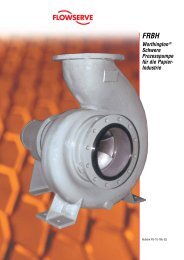
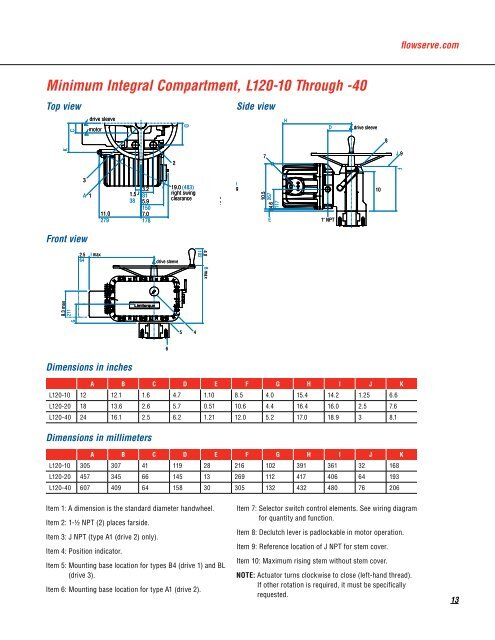
Minimum Integral Compartment, <strong>L120</strong>-10 Through - 0<br />
G<br />
Top view<br />
Front view<br />
2.5<br />
64<br />
K<br />
8.3 max<br />
211<br />
C<br />
I max<br />
G<br />
3<br />
drive sleeve<br />
drive sleeve<br />
motor<br />
motor<br />
K<br />
C<br />
A 1<br />
2.5 I max<br />
64<br />
8.3 max<br />
211<br />
A 1<br />
11.0<br />
279<br />
G<br />
Dimensions in inches<br />
A B C 6 D E F G H I J K<br />
<strong>L120</strong>-10 12 12.1 1.6 4.7 1.10 8.5 4.0 15.4 14.2 1.25 6.6<br />
<strong>L120</strong>-20 18 13.6 2.6 5.7 0.51 10.6 4.4 16.4 16.0 2.5 7.6<br />
<strong>L120</strong>-40 24 16.1 2.5 6.2 1.21 12.0 5.2 17.0 18.9 3 8.1<br />
Dimensions in millimeters<br />
A B C D E F G H I J K<br />
<strong>L120</strong>-10 305 307 41 119 28 216 102 391 361 32 168<br />
<strong>L120</strong>-20 457 345 66 145 13 269 112 417 406 64 193<br />
<strong>L120</strong>-40 607 409 64 158 30 305 132 432 480 76 206<br />
Item 1: A dimension is the standard diameter handwheel.<br />
Item 2: 1-1/2 NPT (2) places farside.<br />
Item 3: J NPT (type A1 (drive 2) only).<br />
3<br />
K<br />
2.5<br />
64<br />
Item 4: Position indicator.<br />
C<br />
3<br />
3.2<br />
3.2 1.5<br />
A 1<br />
81<br />
1.5 38<br />
81 5.9<br />
38 5.9<br />
150<br />
11.0<br />
7.0<br />
279 150 11.0<br />
178<br />
7.0 279<br />
178<br />
I max<br />
drive sleeve<br />
motor<br />
drive sleeve<br />
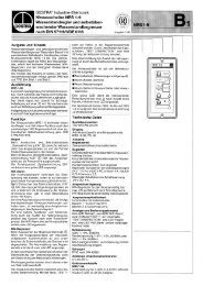
Item 5: Mounting base location for types B4 (drive 1) and BL<br />
(drive 3).<br />
Item 6: Mounting base location for type A1 (drive 2).<br />
2<br />
drive sleeve<br />
6<br />
5<br />
2<br />
D<br />
D<br />
19.0 (483)<br />
19.0 right 3.2<br />
(483) swing<br />
1.5<br />
right clearance<br />
38<br />
swing<br />
81<br />
38 5.9<br />
clearance<br />
150<br />
7.0<br />
178<br />
5<br />
4<br />
4.0<br />
102<br />
drive sleeve<br />
B B max max<br />
4.0<br />
102<br />
4<br />
B max<br />
6<br />
7<br />
2<br />
10.5 10.5<br />
267 4.6 267<br />
117<br />
5<br />
D<br />
19.0 (483)<br />
right swing<br />
clearance<br />
4.6<br />
117<br />
Side view<br />
H<br />
H<br />
D<br />
D<br />
drive sleeve<br />
drive sleeve D<br />
E<br />
E<br />
1" NPT<br />
1" NPT<br />
E 1" NPT<br />
4<br />
4.0<br />
102<br />
B max<br />
7<br />
10.5<br />
4.6 267<br />
117<br />
H<br />
Item 7: Selector switch control elements. See wiring diagram<br />
for quantity and function.<br />
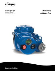
Item 8: Declutch lever is padlockable in motor operation.<br />
Item 9: Reference location of J NPT for stem cover.<br />
Item 10: Maximum rising stem without stem cover.<br />
NOTE: Actuator turns clockwise to close (left-hand thread).<br />
If other rotation is required, it must be specifically<br />
requested.<br />
10<br />
8<br />
J 9<br />
10<br />
drive sleeve<br />
8<br />
F<br />
J 9<br />
F<br />
10<br />
8<br />
flowserve.com<br />
J 9<br />
F<br />
1