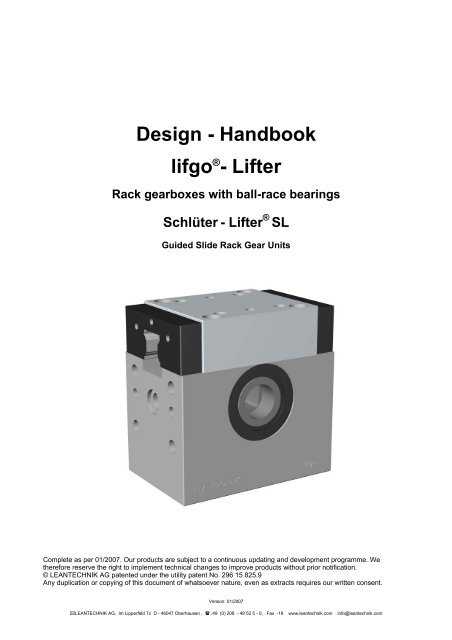
Design - Handbook lifgo®- Lifter - CeeIndustrial
Design - Handbook lifgo®- Lifter - CeeIndustrial
Design - Handbook lifgo®- Lifter - CeeIndustrial

You also want an ePaper? Increase the reach of your titles
YUMPU automatically turns print PDFs into web optimized ePapers that Google loves.
<strong>Design</strong> - <strong>Handbook</strong><br />
lifgo ® - <strong>Lifter</strong><br />
Rack gearboxes with ball-race bearings<br />
Schlüter - <strong>Lifter</strong> ® SL<br />
Guided Slide Rack Gear Units<br />
Complete as per 01/2007. Our products are subject to a continuous updating and development programme. We<br />
therefore reserve the right to implement technical changes to improve products without prior notification.<br />
© LEANTECHNIK AG patented under the utility patent No. 296 15 825.9<br />
Any duplication or copying of this document of whatsoever nature, even as extracts requires our written consent.<br />
Version: 01/2007<br />
�LEANTECHNIK AG, Im Lipperfeld 7c D - 46047 Oberhausen , �..49 (0) 208 - 49 52 5 - 0, Fax -18 www.leantechnik.com info@leantechnik.com
Contents<br />
Chapter 1<br />
Chapter 2<br />
Chapter 3<br />
1.1 References (summary)<br />
1.2 Applications areas for lifgo ® units<br />
2.1 Technical Introduction<br />
2.1.1 Improving successful products<br />
2.1.2 Advantages of the lifting system<br />
2.1.3 Advantages of the lifter<br />
2.1.4 Various positional set-ups of the lifter<br />
2.1.5 Combination<br />
2.1.6 Using the lifter as a rotating and pivoting mechansim<br />
2.2 System Components<br />
2.2.1 Accessories for the lifter<br />
2.2.2 Applications - examples<br />
2.2.2.1 Applications – example 1<br />
2.2.2.2 Applications – example 2<br />
2.2.2.3 Applications – example 3<br />
2.2.2.4 Applications – example 4<br />
2.2.3 Modular designed<br />
2.2.4 Flexible systems - variants<br />
3.1 Line of lifgo ® 3.9 – 4.7<br />
3.1.1 Technical specification of the models<br />
3.1.2 Ascertaining the bearing force<br />
3.1.3 Technical specification - accessories<br />
3.1.4 Unit specification<br />
3.1.5 Unit drilling pattern – Coupling dimensions<br />
3.1.6 VEAS (Vertical Energy Arrest System)<br />
3.1.7 VEAS (Vertical Energy Arrest System) specification<br />
3.1.8 Unit Double specification<br />
3.1.9 Conversion Factors metric / GB – USA<br />
3.2 Gear tooth rack, guide rail and Accessories<br />
Types lifgo ® 3.9 – 4.7<br />
3.2.1 Gear tooth rack specification<br />
3.2.2 Gear tooth rack calculation of length<br />
3.2.3 Lateral load capacity – rack drives<br />
3.2.4 Rack Attachment Points<br />
3.2.5 Rack cover specification<br />
3.2.6 Rack cover calculation of length<br />
3.2.7 Guide rail (without rack profile)<br />
3.2.8 Rack guiding<br />
3.3 Line of lifgo ® linear 4.1 - 4.3<br />
3.3.1 Technical specification of the models<br />
3.3.2 Linear unit specification<br />
3.3.3 VEAS (Vertical Energy Arrest System)<br />
3.3.4 Lifgo linear VEAS unit specification<br />
3.4 Gear tooth rack, guide rail and Accessories<br />
Line of lifgo ® linear 4.1 - 4.3<br />
3.4.1 Linear gear tooth rack specification<br />
3.4.2 Linear Rack guiding<br />
Version: 01/2007<br />
�LEANTECHNIK AG, Im Lipperfeld 7c D - 46047 Oberhausen , �..49 (0) 208 - 49 52 5 - 0, Fax -18 www.leantechnik.com info@leantechnik.com
Contents<br />
Chapter 4<br />
Chapter 5<br />
Chapter 6<br />
Chapter 7<br />
4.1 Line of Schlüter-<strong>Lifter</strong> ® SL 050 - 150<br />
4.1.1 Technical Data<br />
4.1.2 Ascertaining the bearing force<br />
4.1.3 Technical specification - accessories<br />
4.1.4 Lateral load capacity – rack drives<br />
4.1.5 Unit specification<br />
4.2 Gear tooth rack and Accessories<br />
Type Schlüter-<strong>Lifter</strong> ® SL 050 - 150<br />
4.2.1 Gear tooth rack specification<br />
4.2.2 Rack covers<br />
5.1 System Components<br />
Types lifgo ® 3.9 – 4.7, lifgo ® linear 4.1 - 4.3 and Schlüter-<strong>Lifter</strong> ® SL<br />
5.1.1 Profile shaft specification<br />
5.1.2 Locking collar specification<br />
5.1.3 Torsionally rigid tube<br />
5.1.4 Differential coupling<br />
5.1.5 Differential coupling specification<br />
5.1.6 Universal shaft joint specification<br />
5.1.7 Assembly Notices, Cardan Joint<br />
5.1.8 Cardan shaft specification<br />
5.1.9 Fixing brackets drilling pattern<br />
5.1.10 Mounting plates drilling pattern<br />
5.1.11 Lubrication plate<br />
5.1.12 Front-lubricator<br />
5.1.13 Self-lubricator<br />
6.1 Tool Making<br />
Type lifgo ® 4.0<br />
6.1.1 Areas of Application<br />
6.1.2 Rack gear according to company standards<br />
6.1.3 Fixing plate according to WDX standard Ford, Europe<br />
Dimensioned drawing<br />
7.1 Drive Units<br />
Types lifgo ® 3.9 – 4.7, lifgo ® linear 4.1 - 4.3 and Schlüter-<strong>Lifter</strong> ® SL<br />
7.1.1 Drive Units<br />
7.1.2 Drive Units – three phase gear-motor DGM SR/SC<br />
7.1.3 Servomotor<br />
7.1.4 Pneumatic cylinder LZY<br />
7.2 Accessories<br />
Types lifgo ® 3.9 – 4.7, lifgo ® linear 4.1 - 4.3 and Schlüter-<strong>Lifter</strong> ® SL<br />
7.2.1 Gearbox adapter, Coupling and Planet-Gearbox<br />
7.2.2 Bearer block for SGM / ATB units<br />
7.2.3 Shafts adapters<br />
7.2.4 Sliding Naves<br />
7.2.5 Coupling unit specification<br />
7.2.6 Gearbox Adapter for lifgo<br />
7.2.7 Gearbox Adapter for Schlüter<br />
Version: 01/2007<br />
�LEANTECHNIK AG, Im Lipperfeld 7c D - 46047 Oberhausen , �..49 (0) 208 - 49 52 5 - 0, Fax -18 www.leantechnik.com info@leantechnik.com
Contents<br />
Chapter 8<br />
Chapter 9<br />
Chapter 10<br />
Chapter 11<br />
8.1 Assembly and Commissioning<br />
Types lifgo ® 3.9 – 4.7, lifgo ® linear 4.1 - 4.3 and Schlüter-<strong>Lifter</strong> ® SL<br />
8.1.1 Assembly instructions<br />
8.1.2 3.9, 4.0 and 4.1, Insertion of rack<br />
8.1.3 Commissioning<br />
8.1.4 Maintenance & Lubrication intervals and quantity for lifgo<br />
8.1.5 Lubrication intervals for guide blocks and guide rail<br />
8.1.6 VEAS Assembly<br />
9.1 Modular construction of a lifting system an assembly example<br />
Types lifgo ® 3.9 – 4.5<br />
9.1.1 Mounting instructions for lifting device<br />
10.1 Incidentals<br />
Types lifgo ® 3.9 – 4.7, lifgo ® linear 4.1 - 4.3 and Schlüter-<strong>Lifter</strong> ® SL<br />
10.1.1 Coupling nut<br />
10.1.2 Coupling plates<br />
10.1.3 Formular collecting<br />
10.1.4 Data transfer<br />
11.1 Terms<br />
11.1.1 Terms and Conditions of Sale and Delivery<br />
11.1.2 Notes<br />
Version: 01/2007<br />
�LEANTECHNIK AG, Im Lipperfeld 7c D - 46047 Oberhausen , �..49 (0) 208 - 49 52 5 - 0, Fax -18 www.leantechnik.com info@leantechnik.com
Version: 01/2007<br />
Chapter 1<br />
�LEANTECHNIK AG, Im Lipperfeld 7c D - 46047 Oberhausen , �..49 (0) 208 - 49 52 5 - 0, Fax -18 www.leantechnik.com info@leantechnik.com<br />
Types<br />
lifgo ®<br />
lifgo ® linear<br />
Schlüter-<strong>Lifter</strong> ® SL<br />
References (summary)<br />
Applications
Chapter 1<br />
1.1 References (summary)<br />
• ABB<br />
• AEG Hausgeräte GmbH<br />
• Agfa Gevaert AG<br />
• AUDI AG<br />
• AUTOEUROPA<br />
• BENTELER AG<br />
• BMW AG<br />
• BMW Motorsport<br />
• BRAUN GmbH<br />
• BSH BOSCH UND SIEMENS Hausgeräte GmbH<br />
• COMAU SYSTEMS S.P.A. (Italien, Indien)<br />
• CONTINENTAL AG<br />
• DAIMLER CHRYSLER AG<br />
• DEMAG ERGOTECH<br />
• EDAG AG<br />
• FASTI Carl.Aug. Fastenrath GmbH & Co.KG<br />
• FLABEG GmbH & Co.KG<br />
• FORD AG (Global)<br />
• KRUPP DRAUZ<br />
• KUKA Schweißanlagen GmbH<br />
• KÜPPERSBUSCH GmbH<br />
• LÄPPLE GmbH & Co.KG<br />
• MAN Nutzfahrzeuge AG<br />
• MIELE + Cie. GmbH & Co.KG<br />
• MÜLLER WEINGARTEN AG<br />
• NOTHELFER GmbH<br />
• OPEL AG (Deutschland, Spanien)<br />
• RHEINZINK GmbH & Co.KG<br />
• SCHULER AUTOMATION GmbH & Co.KG<br />
• SCHULER CARTEC GmbH & Co.KG<br />
• SEAT S.A.<br />
• SIEMENS-MATSUSHITA Compon. GmbH & Co.KG<br />
• SIEMPELKAMP GmbH & Co.KG<br />
• SKODA AUTO A.S.<br />
• THYSSEN Umformtechnik GmbH<br />
• VIESSMANN-WERKE GmbH & Co.KG<br />
• VOLKSWAGEN AG<br />
• VOLVO PERSONVAGNAR AB<br />
• WESER METALL Umformtechnik GmbH<br />
• WIELAND-WERKE AG<br />
• WITTE Umformtechnik GmbH & Co.KG<br />
• YTONG DEUTSCHLAND AG<br />
Version: 01/2007<br />
�LEANTECHNIK AG, Im Lipperfeld 7c D - 46047 Oberhausen , �..49 (0) 208 - 49 52 5 - 0, Fax -18 www.leantechnik.com info@leantechnik.com
Chapter 1<br />
1.2 Application areas for lifgo ® units<br />
traction - pushing - lifting – lift and shift - lowering - turning - tipping - swiveling<br />
Synchronous motion systems in the automation- manufacturing- and transfer techniques<br />
car industry ceramic industry foodstuff industry<br />
structural chemical engineering railway industry glass industry<br />
white goods manufacturing aerospace industry packaging processing<br />
plastics processing wood processing tyre manufacture<br />
packaging industry furniture industry shipbuilding industry<br />
power generation<br />
Applications Examples<br />
lifting systems<br />
- vibration free synchronous lifting table<br />
- vibration free secondary positioning of broaching tool<br />
load lift systems<br />
- lift station for belt conveyor<br />
- lifting column system for roller-conveyor<br />
lifting table<br />
- final assembly lift station<br />
- lifting table for automatic bending machine<br />
- lift station – automotive industry<br />
- engine/transmission lift station<br />
- lift station for automotive “modeling” table<br />
- hand operated precision lifting tables for scientific instruments<br />
press transfer system<br />
- three-axis press transfer system<br />
- 2-axis transfer table system<br />
lift and tilt system<br />
- body tilt system with vertical adjustment<br />
- tilt system for roller conveyor handling large steel sheets<br />
lift and shift (shuttle) system<br />
- mono-rail shuttle for automotive supplier<br />
- mono-rail shuttle for con-rod machining<br />
- suspended monorail shuttle system for transport of U-Frames for sliding roof<br />
- standing double beam system<br />
advance and stacking system<br />
- chipboard stacking system<br />
- positioning system<br />
- footstep between railway carriage and railway platform<br />
die automation<br />
- double-headed die tool set<br />
- de-burring press die operation<br />
- re-build of die with lifter system<br />
centering system<br />
- centering and lift system for press components prior to robotic stage<br />
- centering of dies to carcass in tyre production<br />
- synchronous centering for glass sheet manufacturing and stacking<br />
Version: 01/2007<br />
�LEANTECHNIK AG, Im Lipperfeld 7c D - 46047 Oberhausen , �..49 (0) 208 - 49 52 5 - 0, Fax -18 www.leantechnik.com info@leantechnik.com
Version: 01/2007<br />
�LEANTECHNIK AG, Im Lipperfeld 7c D - 46047 Oberhausen , �..49 (0) 208 - 49 52 5 - 0, Fax -18 www.leantechnik.com info@leantechnik.com
Version: 01/2007<br />
Chapter 2<br />
�LEANTECHNIK AG, Im Lipperfeld 7c D - 46047 Oberhausen , �..49 (0) 208 - 49 52 5 - 0, Fax -18 www.leantechnik.com info@leantechnik.com<br />
Typ<br />
lifgo ®<br />
Technical Introduction<br />
System - Components
Chapter 2<br />
2.1 Technical Introduction<br />
2.1.1 Improving successful products<br />
lifgo is a modular constructed lifting system, which can be used in the widest possible fields of<br />
application. With just one basic arrangement (for each particular model) the module, with which all<br />
the motional systems are interconnected, is formed. By means of the four models available, the<br />
lifting and moving of small to heavy loads can be accomplished rapidly. The innovative design is<br />
based on the principle of a rack and pinion drive system, and follows the tradition of our proven<br />
Schlüter lifters ® .<br />
The objective of the new development was to provide a user-friendly modular system, with the<br />
requirement:<br />
1. to translate greater outputs using smaller sizes of modules<br />
2. to increase flexibility by increasing the range of application and<br />
3. to reduce accessories to a minimum, yet to retain and improve the „ clip and go „®<br />
rapid assembly system.<br />
2.1.2 Advantages of the lifting system<br />
� Smaller size module with greater outputs<br />
� Logical progression in output capacities between all the models<br />
lifting load of 1 kg to 8,000 kg<br />
transverse force of 1 kg to 11.050 kg<br />
� One basic design for each model<br />
� Easy fitting during installation and assembly due to identical design<br />
and method of operation for all models<br />
� High acceleration and operating speeds (load dependent)<br />
� All faces of the module casing can be used as mating and mounting faces when assembling<br />
� Rapid „clip and go ®“ assembly for the entire lifter system<br />
� Fewer accessories with flexibility in their application, suitable for direct<br />
mounting<br />
� The rack is guided by four ball-race bearings. It guarantees exact guide with<br />
slight deviation and due to the design of rack they pickup high moment of flexion.<br />
� Greater absorption of transverse forces by the gear tooth rack, thus providing<br />
excellent guidance capability<br />
Version: 01/2007<br />
�LEANTECHNIK AG, Im Lipperfeld 7c D - 46047 Oberhausen , �..49 (0) 208 - 49 52 5 - 0, Fax -18 www.leantechnik.com info@leantechnik.com
Chapter 2<br />
2.1 Technical Introduction<br />
2.1.3 Advantages of the lifter<br />
The lifgo lifter is a completely new concept in terms of the design. Only the principle of the rack and<br />
pinion drive has been retained. The casing is fully enclosed on all sides and is totally unaffected by<br />
external influences, such as spray and pressurised water. This applies equally to all necessary<br />
attachments. The rack is guided by four ball-race bearings and is sealed on three sides. As a result,<br />
any escape of lubricant (after the commissioning phase) and any ingress of dirt is prevented. The<br />
racks are able to absorb substantial lateral forces and thus in axial direction adopt the task of acting<br />
as guides (transverse forces). Further guides are unnecessary, which reduces costs. The pinion<br />
shaft located in the casing is provided with a hollow profile. Upon insertion of the profiled shaft, a<br />
frictionally interlocking interface is created between the lifters or between the lifter(s) and the<br />
motor(s). On both ends is seated a centring ring around the pinion shaft. Its task is to accept all<br />
rotating attachments which rotate around the axis, such as gearmotors, drive block, thrust ring, slip<br />
ring or bearer block.<br />
2.1.4 Various positional set-ups of the lifter<br />
The cubic design of the lifgo lifter enables various combinations of set-up to be effected. Centring<br />
pins in each mounting face facilitate ease of alignment and assembly.<br />
The lifgo lifter can be assembled in six differing positions - the example here illustrates the lifter in<br />
single module mode, the „ single lifter“.<br />
Version: 01/2007<br />
�LEANTECHNIK AG, Im Lipperfeld 7c D - 46047 Oberhausen , �..49 (0) 208 - 49 52 5 - 0, Fax -18 www.leantechnik.com info@leantechnik.com
Chapter 2<br />
2.1 Technical Introduction<br />
2.1.5 Combination<br />
In addition to those already shown there are still further possible assembly options such as shown<br />
below. Is not necessary to assemble them adjacent to each other. Please refer here to chapter 2,<br />
sections 2.2.2.1 – 2.2.2.4 Application – examples.<br />
Two single lifters can be assembled in any position in relation to each other uncreasing the<br />
combinations accordingly.<br />
horizontal - vertical on left side horizontal -<br />
vertical on right side aligned<br />
Positioning of the lifter possible on the opposite side or positioned separately!<br />
Use of two lifgo lifter at 90° to each other - shown here the use of a „double lifter“.<br />
2.1.6 Using the lifter as a rotating and pivoting mechanism<br />
By using two modules (of the same model) or bearer blocks, the lifgo lifter system can be used as<br />
rotating and pivoting unit. It is also possible to use combinations off lifters and bearer blocks.<br />
Furthermore, in reverse sequence rotary, linear motion can be converted.<br />
Version: 01/2007<br />
�LEANTECHNIK AG, Im Lipperfeld 7c D - 46047 Oberhausen , �..49 (0) 208 - 49 52 5 - 0, Fax -18 www.leantechnik.com info@leantechnik.com
Chapter 2<br />
2.2 Systemkomponenten<br />
2.2.1 Accessories for the lifter<br />
By the use of accessories the lifgo lifter can be united to form a lifgo system. Each accessory is<br />
dimensioned to suit the particular size of model on which it is be used, and is identical in its design in<br />
each case. The small number of flexible accessories fulfil a multitude of requirements. They are<br />
broken down into four main groups:<br />
1. Accessories - for the rack connections and protection against wear, differential/ heavy load<br />
coupling, protective rack cover, rack coupling for pneumatic and hydraulic cylinder<br />
2. Accessories - for making a rotational connecting joint (torsionally rigid)<br />
profiled shaft, locking ring, universal shaft joints<br />
3. Accessories - for attaching the casing mounting plates, fixing brackets<br />
4. Accessories - for lifgo drives - linear and rotary drives servo-motors, servo drive<br />
block, threephase current, servo gear drive motor, pneumatic cylinder, hydraulic cylinder<br />
2.2.2 Applications - examples<br />
The following pages illustrate the lifgo system by depicting typical application examples. You may<br />
well recognise a concept which is appropriate for your specific problem and if not we would be<br />
pleased to advise.<br />
Beneath the illustrations are explanatory notes and where necessary, examples of calculations. In<br />
the sample calculations the lifting force value (FH) is defined in Newton’s (N) in all cases.<br />
The following lifting force values are used:<br />
lifgo ® 3.9 FH = 550 N/ unit<br />
lifgo ® 4.0 FH = 1.800 N/ unit<br />
lifgo ® 4.1 FH = 3.600 N/ unit<br />
lifgo ® 4.3 FH = 15.800 N/ unit<br />
lifgo ® 4.5 FH = 23.100 N/ unit<br />
lifgo ® 4.7 FH = 80.000 N/ unit<br />
Please Note: Refer to chapter 3, sections 3.1.1 - for Technical specification.<br />
Version: 01/2007<br />
�LEANTECHNIK AG, Im Lipperfeld 7c D - 46047 Oberhausen , �..49 (0) 208 - 49 52 5 - 0, Fax -18 www.leantechnik.com info@leantechnik.com
Chapter 2<br />
2.2 System Components<br />
i<br />
2.2.2.1 Applications - examples<br />
Example 1: lifgo system geometry in standard design (pneumatic operated)<br />
The lifgo system here represents a standard arrangement. It can, for example, be used in press-tool<br />
dies. Advantage: greater load capacity for a small installation space, plus high stroke speed - 25<br />
cyclic strokes/min. The pneumatic cylinder pulls the rack through the lifgo casing and rotates the<br />
pinion shaft having a hollow profile. By means of the inserted profiled shaft, a friction locking<br />
interface is created between the units. The rotary motion of the pinion shaft in the first unit (horizontal<br />
racks) is transmitted to the vertical drive lifgo unit. This moves the rack upwards. Due to the positive<br />
close-tolerances mechanical connection this motional sequence occurs simultaneously for all vertical<br />
units. As a consequence, you have a synchronous lift system. Synchronisation is also assured by the<br />
distributed application of the load. In this set-up the horizontal units fulfils the function of a primary<br />
unit. This means it distributes the lifting force to the vertical units and, as a consequence carry the<br />
greatest load. Load distribution then occurs if the load is transmitted via the pinion and profiled shaft<br />
(rotational interface) to a neighbouring unit. For a simple push-pull application the whole thrust force<br />
can be transmitted.<br />
Please Note: Care should be taken to ensure that the introduced lifting force does not exceed the<br />
maximum permitted lifting force of the (horizontal) primary unit! Please note the<br />
technical data!<br />
Calculation to example 1:<br />
To show how of the calculation is made the values from chapter 2, sections 2.2.2 have been used!<br />
Efficiency factors are not taken into account. (refer chapter 3, sections 3.1.1 Technical<br />
specification.) In using two primary lifgo units, the entire lifting force can be applied twice. This can<br />
then be transferred to the lifgo lifter for each half. The pneumatic cylinder can thus introduce the<br />
doubled force of the primary units.<br />
For example 1geometry there is a lifting force as follows:<br />
lifgo ® 3.9 FH = 550 N x 2 = FH = 1.100 N = cylinder force rating<br />
lifgo ® 4.0 FH = 1.800 N x 2 = FH = 3.600 N = cylinder force rating<br />
lifgo ® 4.1 FH = 3.500 N x 2 = FH = 7.000 N = cylinder force rating<br />
lifgo ® 4.3 FH = 15.800 N x 2 = FH = 31.600 N = cylinder force rating<br />
lifgo ® 4.5 FH = 23.100 N x 2 = FH = 46.200 N = cylinder force rating<br />
lifgo ® 4.7 FH = 80.000 N x 2 = FH = 160.000 N = cylinder force rating<br />
Version: 01/2007<br />
�LEANTECHNIK AG, Im Lipperfeld 7c D - 46047 Oberhausen , �..49 (0) 208 - 49 52 5 - 0, Fax -18 www.leantechnik.com info@leantechnik.com
Chapter 2<br />
2.2 System Components<br />
2.2.2.2 Applications – example 2, lifgo Systematic arrangement (pneumatic)<br />
This arrangement is further development to example 1. The lifting forces are distributed on 6 lifgo<br />
lifters instead of 4. Since all attachments are plug assembled together, such an enhancement is<br />
achieved without any problems. Based on the unchanged number of primary units, the total lifting<br />
force of the system is equal to that of example 1.<br />
2.2.2.3 Applications – example 3, lifgo Systematic arrangement (pneumatic)<br />
Four primary lifgo units were used in this arrangement. Calculated, this means for:<br />
lifgo ® 3.9 FH = 550 N x 4 = FH = 2.200 N = cylinder force<br />
lifgo ® 4.0 FH = 1.800 N x 4 = FH = 7.200 N = cylinder force<br />
lifgo ® 4.1 FH = 3.500 N x 4 = FH = 14.000 N = cylinder force<br />
lifgo ® 4.3 FH = 15.800 N x 4 = FH = 63.200 N = cylinder force<br />
lifgo ® 4.5 FH = 23.100 N x 4 = FH = 92.400 N = cylinder force<br />
lifgo ® 4.7 FH = 80.000 N x 4 = FH = 320.000 N = cylinder force<br />
Version: 01/2007<br />
�LEANTECHNIK AG, Im Lipperfeld 7c D - 46047 Oberhausen , �..49 (0) 208 - 49 52 5 - 0, Fax -18 www.leantechnik.com info@leantechnik.com
Chapter 2<br />
2.2 System Components<br />
2.2.2.4 Applications – example 4, system arrangement using a servo gearmotor<br />
In this case, the drive is a servomotor. Here also, the drive unit is connected to the lifgo lifters via the<br />
profile shafts which are pushed into the lifters, providing a frictional connection. For all lifgo sizes, the<br />
profile shaft has been designed in such a way that upon insertion, the position of the pinions in<br />
relation to one another is synchronised. This ensures that the vertical racks will always have the<br />
same positional height. Incorrect assembly is thus impossible. Under computer control, the<br />
servomotor moves to positions with precise repeatability. When several drives are used, one motor<br />
assumes the control function, which is mirrored by all of the other drives to the same degree of<br />
accuracy.<br />
Calculation to example 4:<br />
The power distribution 3-way gear units have been dimensioned so that they can transmit the<br />
maximum torque of two lifgo units in both axial directions. The total lift force is therefore 4 times that<br />
of a single lifgo unit (please see chapter 2, sections 2.2.2 values).<br />
Calculated, this means:<br />
lifgo ® 3.9 FH = 550 N x 4 = FH = 2.200 N = lift force<br />
lifgo ® 4.0 FH = 1.800 N x 4 = FH = 7.200 N = lift force<br />
lifgo ® 4.1 FH = 3.500 N x 4 = FH = 14.000 N = lift force<br />
lifgo ® 4.3 FH = 15.800 N x 4 = FH = 63.200 N = lift force<br />
lifgo ® 4.5 FH = 23.100 N x 4 = FH = 92.400 N = lift force<br />
lifgo ® 4.7 FH = 80.000 N x 4 = FH = 320.000 N = lift force<br />
Version: 01/2007<br />
�LEANTECHNIK AG, Im Lipperfeld 7c D - 46047 Oberhausen , �..49 (0) 208 - 49 52 5 - 0, Fax -18 www.leantechnik.com info@leantechnik.com
Chapter 2<br />
2.2 System Components<br />
2.2.3 Modular designed<br />
The solutions depicted here and in more detail in the separate Application Guide selection only of<br />
practical applications. Most systems make full use of the lifgo “clip and go” assembly system which<br />
simplifies both design layout work and later assembly. In addition however it will be found that<br />
modifications to later for product changes can be made by simple adjustment or at the worst be<br />
interchanging some components eg longer racks for uncreased stroke. Our precise manufacture<br />
provides guaranteed service life with minimal maintenance. As a result, you have more time to spend<br />
on finding the constructive solution and can build this using the lifgo modular system into complete<br />
units.<br />
We will be only too pleased to help in finding a solution !<br />
Version: 01/2007<br />
�LEANTECHNIK AG, Im Lipperfeld 7c D - 46047 Oberhausen , �..49 (0) 208 - 49 52 5 - 0, Fax -18 www.leantechnik.com info@leantechnik.com
Chapter 2<br />
2.2 System Components<br />
2.2.4 Flexible systems - variants<br />
basic models lifgo 3.9 – 4.7<br />
The six basic types can be combinated and extended (each type) in different variants.<br />
Lifgo-double - design<br />
With two rack gear guides,<br />
e.g. for acquiring (grab function),<br />
telescoping or for centring parts etc<br />
lifgo rack for integrated feed of medium<br />
air pressure, - vacuum, - cooling liquid, - alkaline solution (conditional)<br />
Version: 01/2007<br />
�LEANTECHNIK AG, Im Lipperfeld 7c D - 46047 Oberhausen , �..49 (0) 208 - 49 52 5 - 0, Fax -18 www.leantechnik.com info@leantechnik.com
Version: 01/2007<br />
Chapter 3<br />
�LEANTECHNIK AG, Im Lipperfeld 7c D - 46047 Oberhausen , �..49 (0) 208 - 49 52 5 - 0, Fax -18 www.leantechnik.com info@leantechnik.com<br />
Types<br />
lifgo ®<br />
lifgo ® linear<br />
Technical Data<br />
Gear tooth rack, guide rail and<br />
Accessories
Chapter 3<br />
3.1 Type lifgo ® 3.9 – 4.7<br />
i<br />
3.1.1 Technical specification of the models<br />
lifgo ®<br />
Unit 3.9 4.0 4.1 4.3 4.5 4.7<br />
Casing bearing force N 3.300 5.800 12.000 26.000 63.000 180.000<br />
1) Force of stroke N 550 1.800 3.500 15.800 23.100 80.000<br />
Speed of stroke m/s 1,000 0,830 0,830 0,500 0,416 0,250<br />
Speed of stroke m/min. 60 50 50 30 25 15<br />
Acceleration max. m/s² 5 7 10 4 3 2<br />
Torque max. Nm 3,3 18 70 475 1.040 7800<br />
Pitch circle diameter mm 12 20 40 60 90 196<br />
Gearing mm/α-1° mm 0,1047 0,1745 0,349 0,524 0,785 1,710<br />
Gearing stroke/360° mm 37,69 62,83 125,66 188,49 282,74 615,75<br />
Temperature resistance<br />
Efficiency 1 0,92 0,92 0,92 0,92 0,92 0,90<br />
Profile shaft -<br />
„clip and go ® “ joint<br />
º C 80 80 80 80 80 80<br />
VK 6<br />
square<br />
PG 14<br />
polygonal<br />
Version: 01/2007<br />
PG 20<br />
polygonal<br />
KW 42<br />
spline shaft<br />
SW 46<br />
hexagon<br />
�LEANTECHNIK AG, Im Lipperfeld 7c D - 46047 Oberhausen , �..49 (0) 208 - 49 52 5 - 0, Fax -18 www.leantechnik.com info@leantechnik.com<br />
Flange<br />
Acc. Project<br />
Weight kg 0,55 1,2 3 12 39 162<br />
1) Values given for max. acceleration a = 5 m/s². Chapter 3, sections 3.1.2, heed FMA calculation.<br />
Please Note: An estimation of the service life in connection with the rack gear should be<br />
requested as per the project data!
Chapter 3<br />
3.1 Type lifgo ® 3.9 – 4.7<br />
i<br />
i<br />
3.1.2 Ascertaining the bearing force<br />
Bearing forces in the technical specification (Chapter 2, sections 2.2.2) are based on the max.<br />
acceleration value a (m/s²). If you alter the rate of acceleration, then the bearing force alters too.<br />
Note Less acceleration (a= m/s²) > greater bearing force<br />
Higher acceleration (a= m/s²) > less bearing force.<br />
In the layout of the system, consider the function of the lifgo modules as primary unit,<br />
because even here the total loading on any one lifter must not be exceeded.<br />
FMA - calculation<br />
FL - Static loading [N] FZ - Static loading on rack [N]<br />
mL - Weight of lifting load [kg] mZ - Weight of rack [kg]<br />
a - Acceleration of drive [m/s²] > servo-motor, pneumatic cylinder<br />
Formula 1<br />
Lifting load - vertical FV = FL + FZ + [(mL + mZ) x a] + 20 N x 1,08 = [N]<br />
Lifting load - horizontal FH = [(mL + mZ) x a] + 20 N x 1,08 = [N]<br />
3.1.3 Technical specification - accessories<br />
In arranging the layout, the technical scope of the accessories in terms of application is to be taken<br />
into account. All components which transmit forces for drawing or pushing or transmit moments of<br />
torque can be found in the following table. The data given correspond to the maximum values and<br />
must not be exceeded. They relate to the tabulated values of chapter 3, sections 3.1.1.<br />
lifgo ® Unit 3.9 4.0 4.1 4.3 4.5 4.7<br />
Profile shaft Nm 5 25 110 900 2.100 Acc. Project<br />
Straightness mm/m 0,3 0,3 0,3 0,3 0,3 Acc. Project<br />
Torsional movement °/m 1 1 1 1 1 Acc. Project<br />
Rack buckling length mm 0,055 0,120 0,09 0,10 0,15 Acc. Project<br />
Profile shaft backlash mm 0,020 0,100 0,085 0,020 0,090 ---<br />
Differential-coupling<br />
No./ force vectors pcs. 7 7 9 5 4 Acc. Project<br />
Coupling unit<br />
Pushing/pulling force F N 6.500 18.000 24.000 63.000 99.000 Acc. Project<br />
Please Note: An estimation of the service life in connection with the rack gear should be<br />
requested as per the project data!<br />
Version: 01/2007<br />
�LEANTECHNIK AG, Im Lipperfeld 7c D - 46047 Oberhausen , �..49 (0) 208 - 49 52 5 - 0, Fax -18 www.leantechnik.com info@leantechnik.com
Chapter 3<br />
3.1 Type lifgo ® 3.9 – 4.7<br />
i<br />
3.1.4 Unit specification<br />
lifgo ® unit 3.9 4.0 4.1 4.3 4.5 4.7<br />
A mm 59 78 107,2 175,2 265 502<br />
B mm 59 78 107,2 175,2 265 502<br />
C mm 47 63 70 120 170 320<br />
D mm 44 60,05 85,95 137,7 206 407<br />
E mm 38 50 45 79 120 270<br />
F mm 13 20 35 54 110 165<br />
G mm 29,5 39 53,6 87,6 132,5 251<br />
H mm 22 29 32,6 48,1 55 161<br />
I mm 15 20 42 79 115 270<br />
Dowel hole K mm Ø 4x4 6x9 6x9 6x9 6x9 20x20<br />
L mm M 5x6 M 5x10 M 8x10 M 10x17 M 16x26 Acc. Project<br />
M mm M 5x10 M 5x13 M 8x13 M 10x20 M 16x28 Acc. Project<br />
ØN x P mm 19K6x3 26K6x1,5 47K6x1 58H7x2 100H7x2 140H7x4<br />
O mm 5,5 10 14 14,5 32,5 75<br />
Q mm M6 M10x1 M10x1 M10x1 M10x1 Acc. Project<br />
T mm 12 24 48 87,6 132,5 251<br />
W mm TN/TN TN/TN M6/TN M6/TN M8x1/M8x1 Acc. Project<br />
Part-No. Standard 39-059-047 40-088-044 41-107-076 43-175-125 45-265-189 47-502-320<br />
weight kg 0,55 1,2 3 12 39 162<br />
Please Note: Tolerance band precision / interference hole ± 0,03<br />
Lubricating holes, threaded or cone nipple (TN)<br />
During the design phase, please ensure that the lubrication holes remain<br />
accessible<br />
Version: 01/2007<br />
�LEANTECHNIK AG, Im Lipperfeld 7c D - 46047 Oberhausen , �..49 (0) 208 - 49 52 5 - 0, Fax -18 www.leantechnik.com info@leantechnik.com
Chapter 3<br />
3.1 Type lifgo ® 3.9 – 4.7<br />
i<br />
i<br />
3.1.5 Unit drilling pattern - Coupling dimensions<br />
In the following table are the drilling patterns of the three lifgo units (for direct assembly). For the use<br />
of brackets refer to chapter 5, sections 5.1.9 - fixing brackets or chapter 5, sections 5.1.10 -<br />
mounting plates.<br />
Please Note: The drilling patterns are marked according to the position (Floor space) chapter 2,<br />
sections 2.1.4, ”Various positional set-ups for the lifter”.<br />
1<br />
2<br />
a<br />
a<br />
b b<br />
4 x drilled hole e<br />
c d d c<br />
j<br />
2 x dowel hole f 2 x dowel hole f<br />
k<br />
R = 3<br />
l<br />
Version: 01/2007<br />
�LEANTECHNIK AG, Im Lipperfeld 7c D - 46047 Oberhausen , �..49 (0) 208 - 49 52 5 - 0, Fax -18 www.leantechnik.com info@leantechnik.com<br />
R = 3<br />
4 x drilled hole e<br />
3 4<br />
2 x dowel hole f 2 x dowel hole f<br />
4 x drilled hole e<br />
k<br />
4 x drilled hole e<br />
lifgo ® Unit 3.9 4.0 4.1 4.3 4.5 4.7<br />
a mm 38 50 45 79 120<br />
b mm 30 20 42 79 115<br />
c mm 7,5 10 21 39,5 77,5<br />
d mm 5,5 10 14 14,5 32,5<br />
e mm Ø 5,5 M5 Ø 6 M5 Ø 9 M8 Ø11 M10 Ø17 M16<br />
f mm Ø 4 H7 Ø 6 H7 Ø 6 H7 Ø 6 H7 Ø 6 H7<br />
j mm 5 8 15 26,5 40<br />
k mm 18 22 28 48 67<br />
l mm 18 22 26 48 67<br />
Please Note: Tolerance band precision / interference holes ± 0,03<br />
j<br />
a<br />
a<br />
Special connection.. Please<br />
request drawing
Kapitel 3<br />
3.1 Types lifgo ® 3.9 – 4.7<br />
i<br />
3.1.6 VEAS (Vertical Energy Arrest System)<br />
This mechanical arrest system for the model types listed above includes the following features:<br />
- Precise interlocking interface, robust, designed for every module dependent position.<br />
- Prevents uncontrolled downward travel should the power fail<br />
The VEAS is used to move the system to a “maintenance and repair” position and secure it in this<br />
position. It is also used to lock the system in a particular access position. This is done by first<br />
releasing the pneumatic cylinder; the vertical drive then initiates downward travel at creep speed until<br />
the locking bolt of the VEAS slides into place.<br />
The system is now “mechanically secured”. Maintenance staff can now safely access the area. In<br />
order to release the locked system, the pneumatic cylinder is energised and the VEAS is lifted 2xto at<br />
creep speed working against the load. The system is now released.<br />
The VEAS mechanism can also be used to prevent uncontrolled downward motion in the system in<br />
the event of a power failure..<br />
Important: VEAS is not a brake with which an EMERGENCY STOP can be carried out. VEAS<br />
should only be operated once the system has come to a halt. If the VEAS is operated while the<br />
system is in motion, then the lifgo ® and the VEAS is to be immediately replaced. The VEAS locks<br />
the system in one direction only (the direction against the load). The other direction is not blocked<br />
(ratchet). Each VEAS component is designed to secure one load point only. In order to ensure<br />
correct functionalty at all times, the VEAS should be operated at least once per week. The VEAS<br />
mechanism complies with the requirements of safety class 2.<br />
lifgo ® Unit 4.0 VEAS 4.1 VEAS 4.3 VEAS 4.5 VEAS 4.7 VEAS<br />
Casing bearing<br />
force N --- 12.000 26.000 --- ---<br />
brake holding load N --- 3.500 15.800 --- ---<br />
Part-No.<br />
Pneumatic cylinder<br />
version<br />
Pneumatic Cylinder Version:<br />
Voltage: 24 V direct current 0.83 Ampere<br />
Inductive switch (IS) has been preset at the factory!<br />
2 x PNP make contacts 24 V DC<br />
On Inquiry 41-107-101 43-175-101 On Inquiry On Inquiry<br />
weight kg --- 3,5 13,5 --- ---<br />
Version: 01/2007<br />
�LEANTECHNIK AG, Im Lipperfeld 7c D - 46047 Oberhausen , �..49 (0) 208 - 49 52 5 - 0, Fax -18 www.leantechnik.com info@leantechnik.com
Chapter 3<br />
3.1 Types lifgo ® 3.9 – 4.7<br />
i<br />
3.1.7 VEAS (Vertical Energy Arrest System) specification<br />
Pneumatic cylinder version<br />
lifgo ® Unit 4.0 VEAS 4.1 VEAS 4.3 VEAS 4.5 VEAS 4.7 VEAS<br />
Part-no.<br />
R mm --- 53 58 --- ---<br />
ØS mm --- 29 36 --- ---<br />
T mm --- 44 70 --- ---<br />
U mm --- 77 - 87 95 - 110 --- ---<br />
V mm --- 29 38 --- ---<br />
pneumatic cylinder<br />
version<br />
On Inquiry 41-107-101 43-175-101 On Inquiry On Inquiry<br />
weight kg --- 3,5 13,5 --- ---<br />
Please Note: During the design phase, please ensure that the lubrication holes remain accessible!!<br />
An estimation of the service life in connection with the rack gear should be<br />
requested as per the project data!<br />
Version: 01/2007<br />
�LEANTECHNIK AG, Im Lipperfeld 7c D - 46047 Oberhausen , �..49 (0) 208 - 49 52 5 - 0, Fax -18 www.leantechnik.com info@leantechnik.com
Chapter 3<br />
3.1 Types lifgo ® 3.9 – 4.7<br />
i<br />
3.1.8 Unit Double specification<br />
lifgo ® Unit 3.9 4.0 4.1 4.3<br />
A mm 59 78 107,2 175,2<br />
B mm 59 78 107,2 175,2<br />
C mm 47 63 70 120<br />
D mm 44 60,05 85,95 137,7<br />
E mm 38 50 45 79<br />
G mm 29,5 39 53,6 87,6<br />
I mm 15 20 42 79<br />
Dowel hole K mm Ø 4x4 6x9 6x9 6x9<br />
L mm M 5x6 M 5x10 M 8x10 M 10x17<br />
M mm M 5x10 M 5x13 M 8x13 M 10x20<br />
ØN x P mm 19K6x3 26K6x1,5 47K6x1 58H7x2<br />
O mm 5,5 10 14 14,5<br />
Q mm M6/M6 M10x1/ M10x1 M10x1/ M10x1 M10x1/ M10x1<br />
W mm TN/TN TN/TN M6/TN 1) M6/TN 1)<br />
Part-no. Standard 39-059-050 40-088-050 41-107-080 43-175-135<br />
weight kg/m 0,65 1,42 3,50 14,40<br />
Please Note: Tolerance band precision / interference hole ± 0,03<br />
Lubricating holes (W), threaded or cone nipple (TN)<br />
During the design phase, please ensure that the lubrication holes remain<br />
accessible!<br />
Version: 01/2007<br />
�LEANTECHNIK AG, Im Lipperfeld 7c D - 46047 Oberhausen , �..49 (0) 208 - 49 52 5 - 0, Fax -18 www.leantechnik.com info@leantechnik.com
Chapter 3<br />
3.1 Types lifgo ® 3.9 – 4.7<br />
3.1.9 Conversion Factors metric / USA - GB<br />
Metric units USA - GB units<br />
Mass Kilogramm 1,0000 kg pound mass 2,20500 lbm<br />
0,4535 kg 1,00000 lbm<br />
Force Newton 1,0000 N pound force 0,22480 lbf<br />
4,4830 N 1,00000 lbf<br />
Torque Newtonmeter 1,0000 Nm Inches,<br />
pound<br />
Version: 01/2007<br />
2,20510 in.lb<br />
0,1127 Nm 1,00000 in.lb<br />
Length Meter 1,0000 m feet 3,28100 ft<br />
0,3048 m 1,00000 ft<br />
Meter 1,0000 m inches 39,37000 in<br />
0,2540 m 1,00000 in<br />
Millimeter 1,0000 mm inches 0,03940 in<br />
25,4000 mm 1,00000 in<br />
Speed Meter/minute 1,0000 m/min. feet/minute 3,28100 ft/min.<br />
0,3048 m/min. 1,00000 ft/min.<br />
1,0000 m/min. 0,05468 ft/s<br />
Meter/Second 1,0000 m/s feet/second 3,28100 ft/s<br />
0,3048 m/s 1,00000 ft/s<br />
18,2900 m/min. 1,00000 ft/s<br />
Acceleration Meter/Second² 1,0000 m/s² feet/second² 3,28100 ft/s²<br />
0,3048 m/s² 1,00000 ft/s²<br />
�LEANTECHNIK AG, Im Lipperfeld 7c D - 46047 Oberhausen , �..49 (0) 208 - 49 52 5 - 0, Fax -18 www.leantechnik.com info@leantechnik.com
Chapter 3<br />
3.2 Gear tooth rack, guide rail and Accessories<br />
Types lifgo ® 3.9 – 4.7<br />
i<br />
i<br />
i<br />
i<br />
3.2.1 Gear tooth rack specification<br />
The rack is used as a pull or push action rack and, at the same time, convents linear motion into<br />
rotary (angular) motion. It is also possible to effect the action in reserve. Sequence (angular to<br />
linear). With the rack-to-pinion shaft interface, positioning of +/- 0,01 mm can be accomplished with<br />
accurate repetition.<br />
The rack is guided by four ball-race bearings and can therefore absorb transverse force.<br />
Consequently, it is suitable as a guide. Additional components are not needed.<br />
Threads are provided at the ends, which are for attaching accessories, i.e. a differential couplings, a<br />
coupling unit (for pneumatic cylinder) or a heavy duty coupling, for effecting an interface for pulling or<br />
pushing actions. In addition. The threads are used for accepting attachments, e.g. devices, which<br />
can be directly mounted.<br />
The rack is supplied in lengths in accordance with your requirement. Please state the length,<br />
defined by the number or teeth. Refer to chapter 3, sections 3.2.2, Equation 2 and 3.<br />
A special rack gear is used for particularly demanding, constant operation with high cycle rates in<br />
three shifts. Please be sure to request a calculation of service life. This model is available in<br />
lengths of up to 1,500 mm.<br />
lifgo ® Unit 3.9 4.0 4.1 4.3 4.5 4.7<br />
Part-no.<br />
Part-no.<br />
A mm 7,2 8,50 9,50 17,35 28,85 50<br />
B mm M6 M8 M10 M16 M20 M36<br />
C mm 15 25 25 44 50 40<br />
D mm 9 12,05 15 22,5 31 65<br />
E mm 15 20 23 45 63 125<br />
m mm 0,5 1,00 2,50 2,50 2,50 7<br />
to mm 1,5708 3,1416 7,8540 7,8540 7,8540 21,9911<br />
rack<br />
standard 12-39-00 12-40-00 12-41-00 12-43-00 12-45-00 12-47-00<br />
rack<br />
special --- 12-40-01 12-41-01 12-43-01 12-45-01 12-47-01<br />
weight kg/m 1,37 2,10 3,10 10,40 22,20 75,20<br />
Note for ordering: Always add the number of teeth to the item reference no. by Z =<br />
Example: Rack for lifgo 4.1, length 162,85 mm > 12-41-00, Z = 21.<br />
Version: 01/2007<br />
�LEANTECHNIK AG, Im Lipperfeld 7c D - 46047 Oberhausen , �..49 (0) 208 - 49 52 5 - 0, Fax -18 www.leantechnik.com info@leantechnik.com
Chapter 3<br />
3.2 Gear tooth rack, guide rail and Accessories<br />
Types lifgo ® 3.9 – 4.7<br />
i<br />
i<br />
i<br />
3.2.2 Gear tooth rack calculation of length<br />
Racks are manufactured in length’s according to your application. These should be identical within a<br />
given system. Ascertain the required length by calculating the number of teeth „Z“. This must be<br />
added to the item reference number of ordering purposes.<br />
Proceed as follows:<br />
Firstly, the theoretical number of teeth „Zt“ of the rack is determined. The values, i.e. the length of<br />
lifgo casing(s), the required stroke, the installation space for protective rack cover and, if needed, the<br />
installation space for any attachments are entered into „equation 2”<br />
Round up the value to the next full number.<br />
The actual length of the rack „Xi“ is determined by „equation 3”.<br />
Calculation:<br />
Zt - theoretical number of teeth GL - length of lifgo casing (s)<br />
Herf- required stroke LZS - Installation space for protect. rack cover<br />
K1 - constant = 5 t0 - tooth pitch = (1,5708; 3,1416; 7,8540; 21,9911)<br />
Z - actual number of teeth B - Installation space according to drawing plan of the<br />
System<br />
Xi - actual length of rack BS - Installation space for the lubrication plate<br />
TS - Installation space of rack<br />
Please Note: Round up this value to the next full number.<br />
Equation 2<br />
Zt = (GL + Herf + LZS + B + BS + TS + K1) : t 0 = > round up to a whole number = Z number of teeth<br />
Equation 3<br />
X i = Z x t0 = mm<br />
Example:<br />
A system containing lifgo 4.1 should allow for a stroke of 120 mm. The rack must traverse a beam<br />
having a depth of 50 mm. A protective rack cover is not provide. Z = ?, X i = ?<br />
Zt = (107,2 + 120 + 0 + 50 + 0 + 0 + 5) : 7,8540 = 35,93 > Z = 36 qty. off<br />
Result: Rack with 36 teeth. > Part No. 12-41-00, Z = 36<br />
Xi = 36 x 7,8540 = 282,744 mm<br />
Result: Total length of rack 282,7 mm.<br />
Please Note: Refer to chapter 3, sections 3.2.6, equation 4 and 5 for calculation the installation<br />
space for the protective rack cover (L ZS).<br />
When using, please take into account the installation space required for the lubrication<br />
plate (Bs), chapter 5, sections 5.1.11 and the AZ mounting plate (Ts), chapter 3,<br />
sections 3.2.4, when calculating the toothed rack.<br />
Version: 01/2007<br />
�LEANTECHNIK AG, Im Lipperfeld 7c D - 46047 Oberhausen , �..49 (0) 208 - 49 52 5 - 0, Fax -18 www.leantechnik.com info@leantechnik.com
Chapter 3<br />
3.2 Gear tooth rack, guide rail and Accessories<br />
Types lifgo ® 3.9 – 4.7<br />
i<br />
i<br />
3.2.3 Lateral load capacity - rack drives<br />
The rack profiles for lifgo lifters are fully supported in linear bearings. As a consequence, the rack<br />
profiles can accommodate high lateral loads. The maximum static and dynamic torque (X, Y and Z<br />
axis) for each size of lifgo unit is shown in the table below.<br />
50% of the linear force rating can be applied at a distance of 100 mm from the lifgo unit!<br />
Check your complete Force Rate, this must not be exceeded under any circumstances.<br />
F x 0,5<br />
100<br />
Y Y<br />
Z<br />
Z<br />
lifgo ® Unit 3.9 4.0 4.1 4.3 4.5 4.7<br />
M ty = M tz dyn. Nm 30 100 270 1.300 4.600 57.000<br />
M ty = M tz stat. Nm 70 165 510 2.430 8.100 99.140<br />
M tx = dyn. Nm 55 190 330 1.800 6.400 72.400<br />
M tx = stat. Nm 130 310 650 3.450 11.400 125.400<br />
Please Note: Should you need to calculate the bending distance of the rack ends, please contact<br />
our technical sales office.<br />
Version: 01/2007<br />
�LEANTECHNIK AG, Im Lipperfeld 7c D - 46047 Oberhausen , �..49 (0) 208 - 49 52 5 - 0, Fax -18 www.leantechnik.com info@leantechnik.com<br />
X<br />
X
Chapter 3<br />
3.2 Gear tooth rack, guide rail and Accessories<br />
Types lifgo ® 3.9 – 4.7<br />
i<br />
3.2.4 Rack Attachment Points<br />
1. Attachment points on end face and sides<br />
with holes for dowel pins and/or holes for<br />
screws.<br />
2. Attachment points on sides and end face.<br />
3. AZ mounting plate set, consisting of:<br />
� Upper welded and fastening plate<br />
� Lower fastening plate with rack-shaped<br />
seat ensuring that the rack is secured<br />
(interlocking) without twisting and tilting<br />
4. AZ mounting plate set (as in 3, above) with<br />
additional fully enclosed rack cover<br />
(bellows). The bellows fastening plate can<br />
be screwed to the AZ mounting plate from<br />
below (see hole J).<br />
Mounting plate with toothed rack profile Upper welded and fastening plate<br />
AZ-Mounting<br />
Plate<br />
Unit 3.9 4.0 4.1 4.3 4.5 4.7<br />
A mm 50 50 60 120 170 ----<br />
B mm 50 50 70 136 170 ----<br />
C mm 50 50 60 136 170 ----<br />
D mm 38 30 45 79 120 ----<br />
E mm 30 38 42 79 120 ----<br />
F mm 24,5 32,4 38,2 70 100 ----<br />
G mm 8,7 10,5 9,2 17 5,5 ----<br />
I mm M4 M4 M8 M10 M16 ----<br />
J mm M3 M3 M3 M4 M4 ----<br />
K mm Ø4H7 Ø6H7 Ø6H7 Ø6H7 Ø6H7 ----<br />
T mm 10 10 10 15 20 ----<br />
Part-no.<br />
Mounting<br />
Plate Set 16-39-50 16-40-50 16-41-50 16-43-50 16-45-50 ---weight<br />
kg 0,350 0,320 0,480 3,400 8,080 ----<br />
Part-no.<br />
Mounting<br />
Plate Rack 16-39-51 16-40-51 16-41-51 16-43-51 16-45-51 ---weight<br />
kg 0,170 0,150 0,250 1,630 3,900 ----<br />
Please Note: Including fastening materials.<br />
Version: 01/2007<br />
�LEANTECHNIK AG, Im Lipperfeld 7c D - 46047 Oberhausen , �..49 (0) 208 - 49 52 5 - 0, Fax -18 www.leantechnik.com info@leantechnik.com<br />
4<br />
3<br />
2<br />
1
Chapter 3<br />
3.2 Gear tooth rack, guide rail and Accessories<br />
Types lifgo ® 3.9 – 4.7<br />
i<br />
i<br />
i<br />
3.2.5 Rack cover specification<br />
In case of high levels of pollution and welding plants, the use of protective rack covers is essential.<br />
Rack guides and casings are thus protected from excessive wear. Fixturing is done either using<br />
Velcro on both sides which is simply pressed onto the facing plate or the Velcro is on one side only<br />
(the lifgo side) and is complemented with a plate on the rack side. Please be sure to take into<br />
account the installation space required, see chapter 3, section 3.2.6.<br />
Please Note: In order to pre-empt the failure of the Velcro fastenings in the case of extreme<br />
contamination (e.g. grease) the bellows fastening should be used.<br />
Fitting and removal can be done in a matter of seconds. The individual folds of the rack cover are<br />
guided over the rack gear by specially shaped intermediate plates. This ensures that a blockage<br />
caused by obstruction of the gearing cannot occur.<br />
The rack cover is supplied according to your requirements . Please state the length, defined by the<br />
number of folds. Rack cover supplied as an assembly unit, including screws. Calculation chapter 3,<br />
sections 3.2.6, Equation 4 and 5.<br />
Important Note: Ambient temperature max. 80° C.<br />
lifgo ® Unit 3.9 4.0 4.1 4.3 4.5 4.7<br />
A mm 45 46 48 85 120 ---<br />
B1 mm 50 43 50 80 118 ---<br />
(Velcro) C1 mm 10 10 10 11 13 ---<br />
(Plate) C2 mm 8 8 8 8 9 ---<br />
a mm 3,5 3,0 3,0 3,0 3,0 ---<br />
c mm 19,5 13 13 18 40 ---<br />
Part-no. Fully<br />
Velcro / Plate 12-39-20 12-40-20 12-41-20 12-43-20 12-45-20 On Inquiry<br />
Part-no. Fully<br />
Velcro / Velcro 12-39-21 12-40-21 12-41-21 12-43-21 12-45-21 On Inquiry<br />
Part-no. Velcro<br />
fastening 12-39-29 12-40-29 12-41-29 12-43-29 12-45-29 On Inquiry<br />
Note for ordering: Including fastening materials<br />
Please add the number of folds to the item ref. number when ordering by F=.<br />
Example: Expansion bellows, full protection for lifgo 4.1, length 57 mm > 12-41-20, F=13<br />
Please Note: During the design phase, please ensure that the lubrication holes remain accessible!<br />
Version: 01/2007<br />
�LEANTECHNIK AG, Im Lipperfeld 7c D - 46047 Oberhausen , �..49 (0) 208 - 49 52 5 - 0, Fax -18 www.leantechnik.com info@leantechnik.com
Chapter 3<br />
3.2 Gear tooth rack, guide rail and Accessories<br />
Types lifgo ® 3.9 – 4.7<br />
i<br />
i<br />
i<br />
i<br />
3.2.6 Rack cover calculation of length<br />
Rack covers are manufactured according to your applications. These should be identical within a<br />
given system. Ascertain the required length by calculating the number of folds „F“. The must be<br />
added to the item reference number for ordering purposes. Two versions, (depending on the model)<br />
are calculated in the same manner.<br />
Proceed as follows:<br />
Firstly, the theoretical number of folds „F“ of the cover is determined. The values, i.e. required stroke<br />
or the extended length of the rack, are entered into „equation 5“.<br />
Calculation:<br />
F t - theoretical number of fold a - installation length - min. per fold<br />
H erf - required stroke b (c-a) - extended length - max. per fold<br />
C1 + C2 - installation space c - draw-out length over all<br />
for Velcro fastener pads (Velcro/Plate)<br />
C1 + C1 - installation space<br />
for Velcro fastener pads (Velcro/Velcro)<br />
Please Note: Round up this value to the next full number.<br />
Equation 4<br />
F t = H erf : b = > round up to whole number = F[qty. off]<br />
Equation 5<br />
L ZS = F x a + C1 + C2 = mm<br />
Please Note: If, for design reasons, the lifter has to be installed to a greater depth than the length<br />
of the standard rack permits for effective operation, then the length of the rack must be manufactured<br />
correspondingly longer. This longer rack length can also be calculated by applying equation 3.<br />
However, if after calculating „L ZS“, it is found to be less than the extra depth involved, the rack need<br />
not be lengthened, and a standard rack would be still surface.<br />
Example:<br />
A system containing lifgo 4.1 should allow for a stroke of 130 mm. The rack cover should be used as<br />
a fully enclosed cover to ensure full protection. > F = ?, L ZS = ?<br />
F t = 130 mm : 10 = 13 > F = 13 qty. off<br />
Result: Rack cover with 13 folds Part No. 12-41-20, F = 13<br />
L ZS = 13 x 3,0 + 10 + 8 = 57 mm<br />
Result: The installation length of rack cover is 57 mm.<br />
Please Note: Length L ZS must be used in „equation 2“, chapter 3, sections 3.2.2. If two covers are<br />
provided for each rack, insert L ZS x 2 into the equation.<br />
Version: 01/2007<br />
�LEANTECHNIK AG, Im Lipperfeld 7c D - 46047 Oberhausen , �..49 (0) 208 - 49 52 5 - 0, Fax -18 www.leantechnik.com info@leantechnik.com
Chapter 3<br />
3.2 Gear tooth rack, guide rail and Accessories<br />
Types lifgo ® 3.9 – 4.7<br />
3.2.7 Guide rail (without rack profile)<br />
Version: 01/2007<br />
Note: „n“= Qty. of hole<br />
Guide rail Unit 3.9 4.0 4.1 4.3 4.5 4.7<br />
A mm 16,20 20,55 24,25 39,85 ---- ----<br />
B mm 15 20 23 45 ---- ----<br />
C mm 4,4 6,0 7,0 14 ---- ----<br />
D mm 7,4 9,4 11,0 20 ---- ----<br />
E mm 5,9 7,4 9,1 16,4 ---- ----<br />
F mm M5 M6 M6 M12 ---- ----<br />
G mm 7,5 9,0 12,0 19,0 ---- ----<br />
H mm 10 10 10 16 ---- ----<br />
I mm 60 60 60 105 ---- ----<br />
Part-no.<br />
for mounting<br />
from above rail 12-39-08 12-40-08 12-41-08 12-43-08 12-45-08 12-47-08<br />
for mounting<br />
from below rail 12-39-09 12-40-09 12-41-09 12-43-09 12-45-09 12-47-09<br />
according to<br />
customer’s<br />
specification rail 12-39-05 12-40-05 12-41-05 12-43-05 12-45-05 12-47-05<br />
weight kg/m 1,4 2,2 3,2 10,6 22,4 75,6<br />
�LEANTECHNIK AG, Im Lipperfeld 7c D - 46047 Oberhausen , �..49 (0) 208 - 49 52 5 - 0, Fax -18 www.leantechnik.com info@leantechnik.com
Chapter 3<br />
3.2 Gear tooth rack, guide rail and Accessories<br />
Types lifgo ® 3.9 – 4.7<br />
i<br />
3.2.8 Rack guiding<br />
Rack guiding Unit 3.9 4.0 4.1 4.3 4.5 4.7<br />
A mm 59 78 107,2 175,2 ---- ----<br />
B mm 47 63 70 120 ---- ----<br />
C mm 24 30 36 60 ---- ----<br />
D mm 19,65 25 30 50 ---- ----<br />
E mm 24,55 32,4 38,2 70,0 ---- ----<br />
F mm 15 20 42 79 ---- ----<br />
G mm 38 50 45 79 ---- ----<br />
ØH mm 4 X 4 6 X 9 6 X 9 6 X 9 ---- ----<br />
I mm M5 X 6 M5 X 10 M8 X 10 M10 X 17 ---- ----<br />
(lubrication hole) W mm TN/TN TN/TN M6/TN M6/TN ---- ----<br />
Part-no. Standard 10-02-39 10-02-40 10-02-41 10-02-43 10-02-45 10-02-47<br />
weight kg 0,20 0,45 1,00 4,80 16,20 ---<br />
Please Note: Tolerance band precision / interference holes ± 0,03<br />
Cone nipple (TN)<br />
During the design phase, please ensure that the lubrication holes remain<br />
accessible!<br />
Version: 01/2007<br />
�LEANTECHNIK AG, Im Lipperfeld 7c D - 46047 Oberhausen , �..49 (0) 208 - 49 52 5 - 0, Fax -18 www.leantechnik.com info@leantechnik.com
Chapter 3<br />
3.3 Line of lifgo ® linear 4.1 – 4.3<br />
i<br />
3.3.1 Technical specification of the models<br />
lifgo ® linear Unit 4.1 4.3<br />
a x b x c mm 107 x 70 x 88,95 175 x 120 x 132,15<br />
Casing bearing force N 8.000 17.000<br />
1) Force of stroke max. N 3.500 12.000<br />
Acceleration max. m/s² 10 10<br />
Speed of stroke m/s 2 2<br />
Speed of stroke m/min. 120 120<br />
Torque max. Nm 70 360<br />
Pitch circle diameter mm 40 60<br />
Gearing mm/α-1° mm 0,349 0,524<br />
Gearing stroke/360° mm 125,66 188,49<br />
Temperature resistance °C 80 80<br />
Efficiency 1 0,92 0,92<br />
Profile shaft -<br />
„clip and go ® “ joint<br />
PG 20<br />
Polygonal<br />
Version: 01/2007<br />
KW 42<br />
spline shaft<br />
Weight kg 3 12<br />
1) Values given for max. acceleration a = m/s². Chapter 3, sections 3.1.2, heed FMA calculation.<br />
Please Note: An estimation of the service life in connection with the rack gear should be requested<br />
as per the project data.!<br />
�LEANTECHNIK AG, Im Lipperfeld 7c D - 46047 Oberhausen , �..49 (0) 208 - 49 52 5 - 0, Fax -18 www.leantechnik.com info@leantechnik.com
Chapter 3<br />
3.3 Line of lifgo ® linear 4.1 – 4.3<br />
i<br />
3.3.2 linear unit specification<br />
lifgo ® linear Unit 4.1 4.3<br />
A mm 88,95 132,15<br />
B mm 107 175<br />
C mm 70 120<br />
D mm 90 135<br />
E mm 45 79<br />
F mm 42 79<br />
G mm 48,15 67,65<br />
H mm Ø 60 90<br />
Ø I x P mm Ø 47 K6 tief 1,5 72 K6 tief 2<br />
J mm M 8x13 M 10x20<br />
Dowel hole K mm Ø 6x9 6x9<br />
L mm M 6x6 M 10x20<br />
M mm 27,95 36,15<br />
N mm 44 --<br />
O mm 53 --<br />
Q mm M10x1 (both side) M10x1 (both side)<br />
S<br />
W<br />
V<br />
mm<br />
mm<br />
mm<br />
43,95<br />
--<br />
2xM10x1 (one side)<br />
90,15<br />
1)<br />
M6/TN<br />
--<br />
Part-no. Standard 41-090-100 43-132-160<br />
weight kg 3 12<br />
Please Note: Tolerance band precision/ interference hole ± 0,02<br />
1) Front side threaded/opposite side lubrication nipple<br />
During the design phase, please ensure that the lubrication holes remain<br />
accessible!<br />
Version: 01/2007<br />
�LEANTECHNIK AG, Im Lipperfeld 7c D - 46047 Oberhausen , �..49 (0) 208 - 49 52 5 - 0, Fax -18 www.leantechnik.com info@leantechnik.com
Chapter 3<br />
3.3 Line of lifgo ® linear 4.1 – 4.3<br />
i<br />
3.3.3 VEAS (Vertical Energy Arrest System)<br />
This mechanical arrest system for the model types listed above includes the following features:<br />
- Precise interlocking interface, robust, designed for every module dependent position.<br />
- Prevents uncontrolled downward travel should the power fail<br />
The VEAS is used to move the system to a “maintenance and repair” position and secure it in this<br />
position. It is also used to lock the system in a particular access position. This is done by first<br />
releasing the pneumatic cylinder; the vertical drive then initiates downward travel at creep speed until<br />
the locking bolt of the VEAS slides into place.<br />
The system is now “mechanically secured”. Maintenance staff can now safely access the area. In<br />
order to release the locked system, the solenoid is energised and the VEAS is lifted 2xto at creep<br />
speed working against the load. The system is now released.<br />
The VEAS mechanism can also be used to prevent uncontrolled downward motion in the system in<br />
the event of a power failure..<br />
Exploded drawing, Refer to chapter 3, sections 3.1.6<br />
Important: VEAS is not a brake with which an EMERGENCY STOP can be carried out. VEAS<br />
should only be operated once the system has come to a halt. If the VEAS is operated while the<br />
system is in motion, then the <strong>lifgo®</strong> and the VEAS is to be immediately replaced. The VEAS locks<br />
the system in one direction only (the direction against the load). The other direction is not blocked<br />
(ratchet). Each VEAS component is designed to secure one load point only. In order to ensure<br />
correct functionalty at all times, the VEAS should be operated at least once per week. The VEAS<br />
mechanism complies with the requirements of safety class 2.<br />
lifgo ® linear Unit --- --- 4.3 VEAS --- ---<br />
Casing bearing force N --- --- 17.000 --- ---<br />
Force of stroke max N --- --- 12.000 --- ---<br />
Part-no. --- --- 43-132-100 --- ---<br />
weight kg --- --- 12 --- ---<br />
Version: 01/2007<br />
�LEANTECHNIK AG, Im Lipperfeld 7c D - 46047 Oberhausen , �..49 (0) 208 - 49 52 5 - 0, Fax -18 www.leantechnik.com info@leantechnik.com
Chapter 3<br />
3.3 Line of lifgo ® linear 4.1 – 4.3<br />
i<br />
i<br />
3.3.4 lifgo linear VEAS unit specification<br />
Please Note: For dimensions not given here, please see chapter 3, page 3.3.2<br />
lifgo ® linear Unit --- --- 4.3 VEAS --- ---<br />
Part-no.<br />
E mm --- --- 79 --- ---<br />
J mm --- --- M10x20 --- ---<br />
K mm --- --- Ø6H7x9 --- ---<br />
MN mm --- --- 62,5 --- ---<br />
Q mm --- --- M10x1 --- ---<br />
R mm --- --- 58 --- ---<br />
S mm --- --- 36 --- ---<br />
T mm --- --- 70 --- ---<br />
U mm --- --- 58 --- ---<br />
V mm --- --- 37,5 --- ---<br />
X mm --- --- 42,5 --- ---<br />
Y mm --- --- 45 --- ---<br />
Z mm --- --- 20 --- ---<br />
pneumatic cylinder<br />
version --- On Inquiry 43-132-101 --- ---<br />
weight kg --- --- 12 --- ---<br />
Please Note: During the design phase, please ensure that the lubrication holes remain accessible!<br />
An estimation of the service life in connection with the rack gear should be<br />
requested as per the project data!<br />
Version: 01/2007<br />
�LEANTECHNIK AG, Im Lipperfeld 7c D - 46047 Oberhausen , �..49 (0) 208 - 49 52 5 - 0, Fax -18 www.leantechnik.com info@leantechnik.com
Chapter 3<br />
3.4 Gear tooth rack, guide rail and Accessories<br />
Line of lifgo ® linear 4.1 – 4.3<br />
i<br />
i<br />
i<br />
3.4.1 linear gear tooth rack specification<br />
The gear teeth rack of the Lifgo® Linear in combination with the drive pinion converts rotary motion<br />
to a push-pull linear motion, or equally linear motion to rotary motion. The Lifgo® Linear rack drive<br />
with profiled ‘plug-in’ drive shaft can achieve a repeatability of +/-0.01mm. The profiled rack is<br />
guided all round by four recirculating ball bearing assemblies and is able to accommodate very high<br />
lateral forces. For this reason the profiled rack can be used as both drive and guide element<br />
avoiding the need for further components.<br />
The mounting face of the Lifgo® Linear rack is provided with tapped holes for assembly to base<br />
frame. Our recommended minimum finish: machined surfaces. Where two Lifgo® Linear rack<br />
rails are used with two drive units (or 4 etc) the linear thrust force is doubled (or quadrupled).<br />
Please Note: A special rack gear is used for particularly demanding, constant operation with high<br />
cycle rates in three shifts. Please be sure to request a calculation of service life. This model is<br />
available in lengths of up to 1,500 mm.<br />
The rack gear is manufactured to your specific requirements. Please define the length by stating<br />
the number of gear teeth. Please note that the rack gear is always divided (to) in a trough of the<br />
gearing. For lengths exceeding 509 gear teeth (3,998mm) the rack gear will be delivered in two or<br />
more parts.<br />
lifgo ® linear Unit 4.1 4.3<br />
A mm 24,25 39,85<br />
B mm 23 45<br />
C mm 12 19<br />
D mm M8 M12<br />
E mm 18,25 37,31 R – R distance radius centre<br />
H mm 10 16<br />
I mm 60 105<br />
R mm 0,40 0,50<br />
Modul mm 2,50 2,50<br />
to mm 7,854 7,854<br />
Part-no.<br />
Part-no.<br />
Rack<br />
Standard 12-41-02 12-43-02<br />
Rack<br />
Sonder 12-41-03 12-43-03<br />
weight kg/m 3,1 10,4<br />
Version: 01/2007<br />
�LEANTECHNIK AG, Im Lipperfeld 7c D - 46047 Oberhausen , �..49 (0) 208 - 49 52 5 - 0, Fax -18 www.leantechnik.com info@leantechnik.com
Chapter 3<br />
3.4 Gear tooth rack, guide rail and Accessories<br />
Line of lifgo ® linear 4.1 – 4.3<br />
i<br />
3.4.2 linear Rack guiding<br />
Rack guiding Unit 4.1 4.3<br />
A mm 107 175<br />
B mm 70 120<br />
C mm 31,05 52,85<br />
D mm 30 50<br />
E mm 38 70<br />
F mm 42 79<br />
G mm 45 79<br />
ØH mm 6 X 9 6 X 9<br />
I mm M8 X 9 M10 X 17<br />
J<br />
K<br />
Lubrication hole W<br />
Lubrication hole V<br />
mm<br />
mm<br />
mm<br />
mm<br />
--<br />
21,4<br />
--<br />
M6 (both side)<br />
8<br />
--<br />
1)<br />
M6/TN<br />
--<br />
Part-no. Standard 10-41-33 10-43-33<br />
weight kg 1,00 4,80<br />
Please Note: Tolerance band precision / interference holes ± 0,03<br />
1) Front side threaded/opposite side lubrication nipple (TN)<br />
During the design phase, please ensure that the lubrication holes remain<br />
accessible!!<br />
Version: 01/2007<br />
�LEANTECHNIK AG, Im Lipperfeld 7c D - 46047 Oberhausen , �..49 (0) 208 - 49 52 5 - 0, Fax -18 www.leantechnik.com info@leantechnik.com<br />
i<br />
Please Note:<br />
A suitable guide rail is to be<br />
found in chapter 3, section<br />
3.2.7, version: “screwed in<br />
place from above”
Version: 01/2007<br />
�LEANTECHNIK AG, Im Lipperfeld 7c D - 46047 Oberhausen , �..49 (0) 208 - 49 52 5 - 0, Fax -18 www.leantechnik.com info@leantechnik.com
Version: 01/2007<br />
Chapter 4<br />
�LEANTECHNIK AG, Im Lipperfeld 7c D - 46047 Oberhausen , �..49 (0) 208 - 49 52 5 - 0, Fax -18 www.leantechnik.com info@leantechnik.com<br />
Types<br />
Schlüter-<strong>Lifter</strong> ® SL<br />
Technical Data<br />
Gear tooth rack and Accessories
Chapter 4<br />
4.1 Line of Schlüter-<strong>Lifter</strong> ® SL<br />
i<br />
4.1.1 Technical Data<br />
Schlüter-<strong>Lifter</strong> ® SL Unit SL 050 SL 150<br />
Casing bearing force N 4.000 10.000<br />
Force of stroke N 500 1.500<br />
Speed of stroke m/s 1,0 1,0<br />
Speed of stroke m/min. 60,0 60,0<br />
Torque max. Nm 5 30<br />
Pitch circle diameter mm 20 40<br />
Gearing mm/α-1° mm 0,1745 0,349<br />
Gearing stroke/360° mm 62,83 125,66<br />
Temperature resistance °C -30 bis +100 -30 bis +100<br />
Efficiency 1 0,8 0,8<br />
Profile shaft -<br />
„clip and go ® “ joint<br />
Version: 01/2007<br />
PG 14 Polygonal PG 20 Polygonal<br />
weight kg 0,6 2,0<br />
Please Note: An estimation of the service life in connection with the rack gear should be<br />
requested as per the project data!<br />
�LEANTECHNIK AG, Im Lipperfeld 7c D - 46047 Oberhausen , �..49 (0) 208 - 49 52 5 - 0, Fax -18 www.leantechnik.com info@leantechnik.com
Chapter 4<br />
4.1 Line of Schlüter-<strong>Lifter</strong> ® SL<br />
i<br />
i<br />
4.1.2 Ascertaining the bearing force<br />
Bearing forces in the technical specification are based on the max. acceleration value a (m/s²). If<br />
you alter the rate of acceleration, then the bearing force alters too.<br />
Note Less acceleration (a= m/s²) > greater bearing force<br />
Higher acceleration (a= m/s²) > less bearing force.<br />
In the layout of the system, consider the function of the Schlüter modules as primary unit, because<br />
even here the total loading on any one lifter must not be exceeded<br />
FMA - calculation<br />
FL - Static loading [N] FZ - Static loading on rack [N]<br />
mL - Weight of lifting load [kg] mZ - Weight of rack [kg]<br />
a - Acceleration of drive [m/s²] > servo-motor, pneumatic cylinder<br />
Formula 1<br />
Lifting load - vertical FV = FL + FZ + [(mL + mZ) x a] + 20 N x 1,08 = [N]<br />
Lifting load - horizontal FH = [(mL + mZ) x a] + 20 N x 1,08 = [N]<br />
4.1.3 Technical specification - accessories<br />
In arranging the layout, the technical scope of the accessories in terms of application is to be taken<br />
into account. All components which transmit forces for drawing or pushing or transmit moments of<br />
torque can be found in the following table. The data given correspond to the maximum values and<br />
must not be exceeded. They relate to the tabulated values of chapter 4, sections 4.1.1<br />
Schlüter ® SL Unit SL 050 SL 150<br />
Profile shaft Nm 25 110<br />
Straightness mm/m 0,3 0,3<br />
Torsional movement °/m 1 1<br />
Rack buckling length mm 0,04 0,1<br />
Profile shaft backlash mm 0,100 0,085<br />
Differential-coupling<br />
No./ force vectors Stück 7 9<br />
Coupling unit<br />
Pushing/pulling force F N 18.000 24.000<br />
Please Note: The wear on the slide bearing is 0.01mm/km at a torque of 0 Nm and with no<br />
additional radial forces bearing on the rack gear!<br />
An estimation of the service life in connection with the rack gear should be<br />
requested as per the project data!<br />
Version: 01/2007<br />
�LEANTECHNIK AG, Im Lipperfeld 7c D - 46047 Oberhausen , �..49 (0) 208 - 49 52 5 - 0, Fax -18 www.leantechnik.com info@leantechnik.com
Chapter 4<br />
4.1 Line of Schlüter-<strong>Lifter</strong> ® SL<br />
i<br />
4.1.4 Lateral load capacity - rack drives<br />
The Schlüter ® SL rack gears are mounted in sliding bearings. Bearing wear is 0.01mm/km at a<br />
torque of 0 Nm and with no additional radial forces acting on the rack gear:<br />
max. slide bearing wear SL 050 ≤ 0.5 mm SL 150 ≤ 1.0 mm<br />
The moments of the rack gear guides (x, y and z) are shown in the table below.<br />
Schlüter ® SL Unit SL 050 SL 150<br />
M tx = dyn. Nm 0 0<br />
M tx = stat. Nm 0 0<br />
M ty = dyn. Nm 45 100<br />
M ty = stat. Nm 500 1000<br />
M tz = dyn. Nm 20 35<br />
M tz = stat. Nm 200 400<br />
Please Note: Should you need to calculate the bending distance of the rack ends, please contact<br />
our technical sales office.<br />
Version: 01/2007<br />
�LEANTECHNIK AG, Im Lipperfeld 7c D - 46047 Oberhausen , �..49 (0) 208 - 49 52 5 - 0, Fax -18 www.leantechnik.com info@leantechnik.com
Chapter 4<br />
4.1 Line of Schlüter-<strong>Lifter</strong> ® SL<br />
i<br />
4.1.5 Unit specification<br />
Schlüter ® SL Unit SL 050 SL 150<br />
A mm 75 110<br />
B mm 75 110<br />
C mm 50 70<br />
D mm 56,5 87,5<br />
E mm 36 50<br />
F mm 60 90<br />
G mm 60 90<br />
H mm 37,5 55<br />
I mm 31,5 55<br />
Dowel hole J mm Ø 6 x 10 6 x 10<br />
K mm Ø 7 9<br />
L mm Ø 26 K 6 47 K 6<br />
M mm 2 2<br />
N mm M10 x 1 M10 x 1<br />
Part-no. Standard SL 050 SL 150<br />
weight kg 0,6 2,0<br />
Hinweis: Tolerance band precision / interference holes ± 0,03<br />
Front side threaded<br />
During the design phase, please ensure that the lubrication holes remain<br />
accessible!<br />
Version: 01/2007<br />
�LEANTECHNIK AG, Im Lipperfeld 7c D - 46047 Oberhausen , �..49 (0) 208 - 49 52 5 - 0, Fax -18 www.leantechnik.com info@leantechnik.com
Chapter 4<br />
4.2 Gear tooth rack and Accessories<br />
Type Schlüter-<strong>Lifter</strong> ® SL<br />
i<br />
i<br />
4.2.1 Gear tooth rack specification<br />
The rack is used as a pull or push action rack and, at the same time, convents linear motion into<br />
rotary (angular) motion. It is also possible to effect the action in reserve.<br />
Threads are provided at the ends, which are for attaching accessories, i.e. a differential couplings, a<br />
coupling unit (for pneumatic cylinder) or a heavy duty coupling, for effecting an interface for pulling or<br />
pushing actions. In addition. The threads are used for accepting attachments, e.g. devices, which<br />
can be directly mounted.<br />
The rack is supplied in lengths in accordance with your requirement. Please state the length,<br />
defined by the number or teeth. Refer to chapter 3, sections 3.2.2, Equation 2 and 3.<br />
Schlüter ® SL Unit SL 050 SL 150<br />
A mmØ 20 30<br />
B mm M8 M10<br />
C mm 20 20<br />
to mm 3,1416 7,8540<br />
Part-no. Rack ZA 050 /.. ZA 150 /..<br />
weight kg/m 2,3 5,1<br />
Note for ordering: Always add the number of teeth to the item reference no. by Z =<br />
Example: Rack for Schlüter ® SL 050, length 162,85 mm > ZA 050, Z = 52.<br />
Version: 01/2007<br />
�LEANTECHNIK AG, Im Lipperfeld 7c D - 46047 Oberhausen , �..49 (0) 208 - 49 52 5 - 0, Fax -18 www.leantechnik.com info@leantechnik.com
Chapter 4<br />
4.2 Gear tooth rack and Accessories<br />
Type Schlüter-<strong>Lifter</strong> ® SL<br />
4.2.2 Rack Covers<br />
It is necessary to fit rack covers if operating in a dirty environment. This will ensure that guide blocks<br />
and casings are protected against high rates of wear. When installed vertically, the spiral covers are<br />
fitted with the end with the largest diameter at the top; if installed horizontally, the end with the<br />
largest diameter is fitted in the direction in which the swarf is ejected. The way in which the individual<br />
spiral windings overlap ensures that they are self-cleaning.<br />
These Schlüter ® SL rack component covers are manufactured for each customer individually.<br />
Please contact us at an early stage so that we can determine your requirements.<br />
i<br />
i<br />
Installation:<br />
Secure the Schlüter ® SL, push the rack inside and<br />
position it. Place the rack cover while still closed over the<br />
rack and on to the base flange, with the narrow end<br />
down. Place the retaining flange on to the rack and<br />
secure it against the matching component opposite.<br />
Set the shortest length of rack travel possible. Check that<br />
the rack cover is properly seated on the base flange.<br />
Release the rack cover as described in the installation<br />
guide. The rack cover will spring open and will<br />
automatically take up the correct position inside the<br />
retaining flange.<br />
Please Note: These spiral rack covers are delivered compressed and<br />
pre-tensioned. It is extremely dangerous to release the wire or<br />
steel tape tension retainers in a careless, negligent manner. Do<br />
not release the tension retainers until the rack cover is under<br />
compression. This is the only way to ensure that the spiral cover will<br />
not shoot upwards, posing a considerable risk to life and limb!<br />
Please Note: If the spiral rack covers are installed vertically with the<br />
largest end uppermost then under normal conditions they are selfcleaning<br />
and maintenance free. However if they are no longer<br />
operating smoothly, we recommend that they be lubricated with a<br />
special spray oil.<br />
Version: 01/2007<br />
�LEANTECHNIK AG, Im Lipperfeld 7c D - 46047 Oberhausen , �..49 (0) 208 - 49 52 5 - 0, Fax -18 www.leantechnik.com info@leantechnik.com
Version: 01/2007<br />
�LEANTECHNIK AG, Im Lipperfeld 7c D - 46047 Oberhausen , �..49 (0) 208 - 49 52 5 - 0, Fax -18 www.leantechnik.com info@leantechnik.com
Version: 01/2007<br />
Chapter 5<br />
�LEANTECHNIK AG, Im Lipperfeld 7c D - 46047 Oberhausen , �..49 (0) 208 - 49 52 5 - 0, Fax -18 www.leantechnik.com info@leantechnik.com<br />
Types<br />
lifgo ®<br />
lifgo ® linear<br />
Schlüter-<strong>Lifter</strong> ® SL<br />
System Components
Chapter 5<br />
5.1 System Components<br />
Types lifgo ® 3.9 – 4.7, lifgo ® linear 4.1 – 4.3 and Schlüter-<strong>Lifter</strong> ® SL<br />
i<br />
i<br />
5.1.1 Profile shaft specification<br />
The profiled shaft produce the torsionally rigid frictional interface for all rotational connections. At the<br />
same time they synchronise the tooth position of the pinion shafts and prevent any possible<br />
chance of error occurring during assembly. Consequently, the profiled shafts differ in the three lifgo<br />
models. Profiled shafts are supplied in lengths to suit the customer’s requirements. Please add the<br />
length „L“ (mm) to the item number.<br />
A A A A A<br />
VK 6 PG 14 PG 20 KW 42 SW 46<br />
lifgo ® , lifgo ® linear Unit 3.9 4.0 4.1 4.3 4.5 4.7<br />
Schlüter-<strong>Lifter</strong> ® Unit --- SL 050 SL 150 --- --- ---<br />
A mm 6 14 20 42 52 ---<br />
Part-no. 18-39-10 18-40-10 18-41-10 18-43-10 18-45-10 n.Projekt<br />
weight kg/m 0,3 1,1 1,8 9,4 14,2 ---<br />
Example: Profile shaft for lifgo 4.1, profile length 250 mm > 18-41-10, L = 250<br />
5.1.2 Locking collar specification<br />
The locking collars secure the profiled shafts in axial direction. Please note that the locking collar<br />
must be fitted to both sides of each profiled piece to prevent the profiled shaft from working its way<br />
out of position!<br />
To prevent penetration of sprayed water, the centre must be pressed slightly in the direction towards<br />
the lifgo unit and be sealed with a ring of grease.<br />
B<br />
C<br />
A - Profil<br />
Version: 01/2007<br />
Site of installation to:<br />
lifgo housing<br />
Bearer block<br />
lifgo ® , lifgo ® linear Unit 3.9 4.0 4.1 4.3 4.5 4.7<br />
Schlüter-<strong>Lifter</strong> ® Unit --- SL 050 SL 150 --- --- ---<br />
B mm 30 30 40 70 110 ---<br />
C mm 15 20 21 21 25 ---<br />
Part-no. 18-39-20 18-40-20 18-41-20 18-43-20 18-45-20 Acc. Project<br />
weight kg 0,1 0,1 0,3 1,5 2,5 ---<br />
Please Note: Including fastening materials.<br />
�LEANTECHNIK AG, Im Lipperfeld 7c D - 46047 Oberhausen , �..49 (0) 208 - 49 52 5 - 0, Fax -18 www.leantechnik.com info@leantechnik.com<br />
L
Chapter 5<br />
5.1 System Components<br />
Types lifgo ® 3.9 – 4.7, lifgo ® linear 4.1 – 4.3 and Schlüter-<strong>Lifter</strong> ® SL<br />
i<br />
5.1.3 Torsionally rigid tube<br />
In order to maintain synchronisation when working with large distances between axes, it is necessary<br />
to increase the strength of the shaft by means of a tubular reinforcement.<br />
lifgo ® , lifgo ® linear Unit 3.9 4.0 4.1 4.3 4.5 4.7<br />
Schlüter-<strong>Lifter</strong> ® Unit --- SL 050 SL 150 --- --- ---<br />
L mm Acc. Project Acc. Project Acc. Project Acc. Project Acc. Project Acc. Project<br />
D mm 20 30 45 115 --- ---<br />
Version: 01/2007<br />
Profiled shaft „A“ chapter 5, sections 5.1.1<br />
Part-no. 18-39-11 18-40-11 18-41-11 18-43-11 --- ---<br />
Please Note: Including fastening materials. Alternatively, cardan shafts can be used where the<br />
distances (L) are large.<br />
�LEANTECHNIK AG, Im Lipperfeld 7c D - 46047 Oberhausen , �..49 (0) 208 - 49 52 5 - 0, Fax -18 www.leantechnik.com info@leantechnik.com
Chapter 5<br />
5.1 System Components<br />
Types lifgo ® 3.9 – 4.7, lifgo ® linear 4.1 – 4.3 and Schlüter-<strong>Lifter</strong> ® SL<br />
i<br />
5.1.4 Differential coupling<br />
The differential coupling is an adjustable unit which is fitted between the racks. The required setting<br />
is attained by lengthening or shortening the coupling. The setting can be fine adjusted within a band<br />
of 1/100 mm and is set after installation. In doing this secure the eyebolt/trunnion unit by means of<br />
the lock nuts. With this closed together, rotate the second unit. The lifgo system is installed and<br />
secured in position on the drive end by means of the drive itself (cylinder or motor), this means that<br />
in altering the length of the differential coupling, the rack can only effectively move in its direction of<br />
operation.<br />
Rotation to the right > differential coupling shorter > rack retracts<br />
Rotation to the left > differential coupling lengthens > rack extends<br />
The change in length X DK of lifgo differential-couplings is 0,5mm/360° angle of rotation. This enables<br />
accurate co-ordination or position to be effected, Since all couplings are supplied with one infinitely<br />
variable setting zone (L DK), basic models are offered which cover a length of X i min. to X i max., in<br />
each case. Please ensure that the screwed-in depths of the threads are as uniform as possible!<br />
In addition to the setting function, the coupling enables compensation to be accomplished too.<br />
Angular deviations of α 5° in the X- and Y- axes are permitted. Height and lateral displacement can<br />
be compensated for or taken into account. Please use the coupling only as drawbar rod. For<br />
using as forcing lever is it necessary to calculate the critical load on a column for design of profile<br />
dimension of cross section. Refer to chapter 5, sections 5.1.5, equation 6.<br />
The opening „D“ for accommodating the couplings are given with its diameter in (ØD) in the<br />
technical specification. This diameter, which is as small as possible, should be heeded without<br />
exception.<br />
eye type bearing fork head<br />
L max.<br />
Version: 01/2007<br />
�LEANTECHNIK AG, Im Lipperfeld 7c D - 46047 Oberhausen , �..49 (0) 208 - 49 52 5 - 0, Fax -18 www.leantechnik.com info@leantechnik.com<br />
L min.<br />
+ -<br />
free effective direction<br />
a<br />
a<br />
unit drill<br />
fix by a looknut<br />
+ left longer<br />
- right shorter<br />
D<br />
D
Chapter 5<br />
5.1 System Components<br />
Types lifgo ® 3.9 – 4.7, lifgo ® linear 4.1 – 4.3 and Schlüter-<strong>Lifter</strong> ® SL<br />
5.1.5 Differential coupling specification<br />
Specification:<br />
A - Axle center between middle / middle lifgo Rotation axis Xi - length of rack<br />
Equation 6 L = A - Xi = adjusted length<br />
Setting zone per differential coupling > LDK = mm max – mm min<br />
Angular deviation of the Y- / Y-axis to straight line max. > α<br />
Change in length (mm) of the coupling for 360°rotation > XDK<br />
Openings through wall for the coupling in mm > ∅D<br />
lifgo ® Unit 3.9 4.0 4.1 4.3 4.5 4.7<br />
LDK mm 16 80 80 90 110 ---<br />
α X-/Y- Grad 4 5 5 5 5 ---<br />
XDK mm/360° 0,5 0,75 0,50 0,50 0,50 ---<br />
D mm 20 42 42 60 80 ---<br />
Setting zone<br />
Part-No.<br />
Setting zone<br />
Part-No.<br />
Setting zone<br />
Part-No.<br />
Setting zone<br />
Part-No.<br />
Setting zone<br />
Part-No.<br />
Setting zone<br />
Part-No.<br />
Setting zone<br />
Part-No.<br />
Setting zone<br />
Part-No.<br />
Setting zone<br />
Part-No.<br />
Setting zone<br />
Part-No.<br />
Special type<br />
Part-No.<br />
mm<br />
min./max.<br />
mm<br />
min./max<br />
mm<br />
min./max<br />
mm<br />
min./max<br />
mm<br />
min./max<br />
mm<br />
min./max<br />
mm<br />
min./max<br />
mm<br />
min./max<br />
mm<br />
min./max<br />
mm<br />
min./max<br />
mm<br />
min./max<br />
See below<br />
the note<br />
See below<br />
the note<br />
See below<br />
the note<br />
See below<br />
the note<br />
See below<br />
the note<br />
See below<br />
the note<br />
See below<br />
the note<br />
See below<br />
the note<br />
See below<br />
the note<br />
See below<br />
the note<br />
On inquiry<br />
13-39-00<br />
228-308<br />
13-40-10<br />
308-388<br />
13-40-11<br />
388-468<br />
13-40-12<br />
468-548<br />
13-40-13<br />
548-628<br />
13-40-14<br />
628-708<br />
13-40-15<br />
708-788<br />
13-40-16<br />
788-868<br />
13-40-17<br />
868-948<br />
13-40-18<br />
948-1028<br />
13-40-19<br />
On inquiry<br />
13-40-00<br />
Version: 01/2007<br />
228-308<br />
13-41-10<br />
308-388<br />
13-41-11<br />
388-468<br />
13-41-12<br />
468-548<br />
13-41-13<br />
548-628<br />
13-41-14<br />
628-708<br />
13-41-15<br />
708-788<br />
13-41-16<br />
788-868<br />
13-41-17<br />
868-948<br />
13-41-18<br />
948-1028<br />
13-41-19<br />
On inquiry<br />
13-41-00<br />
280-370<br />
13-43-10<br />
370-460<br />
13-43-11<br />
460-550<br />
13-43-12<br />
550-640<br />
13-43-13<br />
640-730<br />
13-43-14<br />
730-820<br />
13-43-15<br />
820-910<br />
13-43-16<br />
910-1000<br />
13-43-17<br />
1000-1090<br />
13-43-18<br />
1090-1180<br />
13-43-19<br />
On inquiry<br />
13-43-00<br />
500-610<br />
13-45-10<br />
610-720<br />
13-45-11<br />
720-830<br />
13-45-12<br />
830-940<br />
13-45-13<br />
940-1050<br />
13-45-14<br />
1050-1160<br />
13-45-15<br />
1160-1270<br />
13-45-16<br />
1270-1380<br />
13-45-17<br />
1380-1490<br />
13-45-18<br />
1490-1600<br />
13-45-19<br />
On inquiry<br />
13-45-00<br />
weight kg 1-2 1-2 1-4 4-12 15-28<br />
---<br />
---<br />
Note for order: By quoting dimension „L“ after the item number, the differential coupling is supplied<br />
in a present state. For lifgo 3.9 the dimension note is necessary.<br />
�LEANTECHNIK AG, Im Lipperfeld 7c D - 46047 Oberhausen , �..49 (0) 208 - 49 52 5 - 0, Fax -18 www.leantechnik.com info@leantechnik.com<br />
---<br />
---<br />
---<br />
---<br />
---<br />
---<br />
---<br />
---<br />
---<br />
---
Chapter 5<br />
5.1 System Components<br />
Types lifgo ® 3.9 – 4.7, lifgo ® linear 4.1 – 4.3 and Schlüter-<strong>Lifter</strong> ® SL<br />
i<br />
i<br />
5.1.6 Universal shaft joint specification<br />
Universal shaft joints are used for angular interface transmission or torque. If lifgo units are installed<br />
which deviate from a common axis, then two versions of universal shaft joints are available to suit<br />
each profile form and model:<br />
lifgo 3.9, 4.0 and 4.1 Universal shaft joint - single<br />
lifgo 3.9, 4.0 and 4.1 Universal shaft joint - double<br />
If the mounting surfaces being uneven (e.g. unmachined plate, etc.), it is likely that the profiled shaft<br />
cannot be pushed by the pinion shafts without inducing stress. In order not to overload the bearings<br />
by stress force, it is recommended to use two single- type universal shaft joints. The joints are to be<br />
fixed by the use of locking screws.<br />
The maximum angle of deflection „ß“ for each joints is 45 ° in X-/ Y- axis, the assembly notices<br />
chapter 5, sections 5.1.7 and the insertion depth of the profile being dimension „B“. Refer to chapter<br />
5, sections 5.1.1.<br />
- single - - double -<br />
lifgo ® , lifgo ® linear Unit 3.9 4.0 4.1 4.3 4.5 4.7<br />
Schlüter-<strong>Lifter</strong> ® Unit --- SL 050 SL 150 --- --- ---<br />
A mm 48 108 108 --- --- ---<br />
A1 mm 74 156 156 --- --- ---<br />
B mm 13 30 30 --- --- ---<br />
C mm 20 40 40 --- --- ---<br />
D mm 24 54 54 --- --- --ß<br />
Grad 45 45 45 --- --- ---<br />
Part-no. 18-39-31 18-40-31 18-41-31 --- --- ---<br />
Universal shaft<br />
Joint - single<br />
Universal shaft<br />
Joint - single<br />
Version: 01/2007<br />
Universal shaft<br />
Joint - single<br />
Part-no. 18-39-32 18-40-32 18-41-32 --- --- ---<br />
Universal shaft<br />
Joint - double<br />
Universal shaft<br />
Joint - double<br />
Universal shaft<br />
Joint - double<br />
weight kg 0,5 / 1,0 0,8 / 1,1 0,7 / 1,0 --- --- ---<br />
Please Note: Including fastening materials.<br />
�LEANTECHNIK AG, Im Lipperfeld 7c D - 46047 Oberhausen , �..49 (0) 208 - 49 52 5 - 0, Fax -18 www.leantechnik.com info@leantechnik.com
Chapter 5<br />
5.1 System Components<br />
Types lifgo ® 3.9 – 4.7, lifgo ® linear 4.1 – 4.3 and Schlüter-<strong>Lifter</strong> ® SL<br />
i<br />
5.1.7 Assembly Notices, Cardan Joint<br />
Cardan joints and cardan shafts are components for transmitting rotary motion and handle the<br />
transfer of torque from one drive to another.<br />
Two shafts are connected to one another at a fixed angle with a single cardan joint. If the driving<br />
shaft has a constant rotary speed then the driven shaft's rotary motion will be irregular. This<br />
irregularity – also known as gimbal error – is caused by rotary angle advance and retard motion of<br />
the driven shaft with respect to nominal rotary motion. These rotary fluctuations are similar to a sine<br />
wave. This irregularity increases with increased angle α difference between the two shafts, i.e.:<br />
A single cardan joint should only be used in applications where such rotational irregularity is<br />
tolerable. This irregularity can be compensated by employing a pair of single cardan joints<br />
successively or by using a pre-fabricated double cardan joint. When assembled correctly, the<br />
irregularity caused by the first shaft joint will be cancelled by the second, providing that the following<br />
requirements are observed (as specified by DIN 808):<br />
1. Observe correct journal cross orientation when using two single shaft joints; both inside yokes<br />
should be in a single plane.<br />
Correct<br />
same yoke plane<br />
2. The deflection angle must be the same at both ends.<br />
Correct<br />
angle α and β are identical<br />
α α<br />
β<br />
Version: 01/2007<br />
False<br />
yoke planes at 90° offset<br />
False<br />
angle α and β are<br />
different<br />
Please Note: If the driving shaft and the driven shaft are allowed to move laterally, only parallel<br />
motion may be permitted.<br />
Shaft bearings for jointed shafts – or double jointed shafts – should be located as<br />
close as possible to the shafts' joints.<br />
�LEANTECHNIK AG, Im Lipperfeld 7c D - 46047 Oberhausen , �..49 (0) 208 - 49 52 5 - 0, Fax -18 www.leantechnik.com info@leantechnik.com<br />
β
Chapter 5<br />
5.1 System Components<br />
Types lifgo ® 3.9 – 4.7, lifgo ® linear 4.1 – 4.3 and Schlüter-<strong>Lifter</strong> ® SL<br />
i<br />
5.1.8 Cardan shaft specification<br />
Cardan shafts are used for the rotary, positive transmission of torque. If lifgo lifters are fitted so that<br />
they do not lie in one axis, the following types are available:<br />
lifgo 4.3, 4.5 and 4.7 dual jointed cardan shaft<br />
Version: 01/2007<br />
�LEANTECHNIK AG, Im Lipperfeld 7c D - 46047 Oberhausen , �..49 (0) 208 - 49 52 5 - 0, Fax -18 www.leantechnik.com info@leantechnik.com<br />
i<br />
Please observe the maximum angle of<br />
deviation “ß” per joint in the X / Y axis.<br />
The depth of insertion of the profile is the<br />
dimension “A1”- 5mm.<br />
See chapter 5, sections 5.1.1 for the form<br />
of the profiled shaft<br />
lifgo ® , lifgo ® linear Unit 4.3 4.3 4.5 4.5 4.7<br />
A mm Acc. Project Acc. Project Acc. Project Acc. Project Acc. Project<br />
A1 mm 62 62 62 62 ---<br />
B mm --- --- --- --- ---<br />
C mm 100 100 120 120 ---<br />
D mm 42 46 46 60 ---<br />
Break angle ß Grad 18 35 18 35 ---<br />
Part-no. 18-43-32 18-43-33 18-45-32 18-45-33 18-47-32<br />
Cardan shaft<br />
double<br />
Cardan shaft<br />
double<br />
Cardan shaft<br />
double<br />
Cardan shaft<br />
double<br />
Cardan shaft<br />
double<br />
weight kg Acc. Project Acc. Project Acc. Project Acc. Project Acc. Project<br />
Please Note: Including fastening materials.
Chapter 5<br />
5.1 System Components<br />
Line of lifgo ® 3.9 – 4.7<br />
i<br />
5.1.9 Fixing brackets drilling pattern<br />
If it is impossible to bolt the lifgo units directly on to the mounting surface, one can use fixing<br />
brackets instead. There are two versions available (depending on the model)<br />
Single type - for fixing of one unit<br />
Double type - for fixing of two units next to each other.<br />
Fixing brackets supplied in pairs as an assembly unit, including screws.<br />
lifgo ® Unit 3.9 4.0 4.1 4.3 4.5 4.7<br />
A mm 38 50 45 79 120 ---<br />
B mm 20 20 20 40 60 ---<br />
C mm 15,5 13 13,5 30 40 ---<br />
D mm 30 40 40 60 70 ---<br />
E mm 4 4 4 5 20 ---<br />
F mm 5,5 ∅7 ∅9 ∅11 ∅17,5 ---<br />
G mm 47 63 70 120 170 ---<br />
H mm 94 126 140 240 340 ---<br />
I mm 9 13 25 41 50 ---<br />
Part-no. single 17-39-10 17-40-10 17-41-10 17-43-10 17-45-10 On inquiry<br />
Part-no. double 17-39-20 17-40-20 17-41-20 17-43-20 17-45-20 On inquiry<br />
weight kg 0,2 / 0,4 0,2 / 0,4 02 ,/ 0,4 0,4 / 0,8 2,0 / 4,0 ---<br />
Please Note: The drilling patterns for the fixing brackets and plates are identical. The mounting<br />
dimensions are given at chapter 3, sections 3.1.5<br />
Version: 01/2007<br />
�LEANTECHNIK AG, Im Lipperfeld 7c D - 46047 Oberhausen , �..49 (0) 208 - 49 52 5 - 0, Fax -18 www.leantechnik.com info@leantechnik.com
Chapter 5<br />
5.1 System Components<br />
Line of lifgo ® 3.9 – 4.7<br />
i<br />
i<br />
5.1.10 Mounting plates drilling pattern<br />
It is recommended to use mounting plates if the bearing plate or similar is not of sufficient strength or<br />
rigidity. Furthermore, any variance in heights can be matched and compensated. In using lifgo drive<br />
blocks, mounting plates must be used. If a lifgo unit is to be used as a pivotal unit, mounting plates<br />
provide the necessary height for the unit to be able to rotate clear of the centre axis The lifgo unit is<br />
initially bolted to the mounting plate, then as a combined assembly, positioned and installed. The<br />
position of the lifters can be determined as required. Two versions (depending on the model) are<br />
available):<br />
Single-type - for fixing of one unit.<br />
Double-type - for fixing of two units next to each other.<br />
Hinweis: Mounting plate supplied as an assembly unit including screws.<br />
lifgo ® Unit 3.9 4.0 4.1 4.3 4.5 4.7<br />
A mm 47 63 70 120 170 ---<br />
B mm 38 50 45 79 120 ---<br />
C mm 94 126 140 240 340 ---<br />
D mm 9 13 25 41 50 ---<br />
E mm 100 118 154 225 335 ---<br />
F mm 88 104 134 200 300 ---<br />
G mm 18 -- 26 48 66,7 ---<br />
H<br />
In the ground<br />
mm 18 -- 28 48 65 ---<br />
4/8 x manufact. I mm M5 M6 M8 M10 M16 ---<br />
J mm 5 -- 15 26,5 40,5 ---<br />
K mm Ø5,5 Ø7 Ø9 Ø11 Ø17,5 ---<br />
L mm -- Ø38 -- -- -- ---<br />
M mm -- 21 -- -- -- --t<br />
mm 7 8 12 15 20 ---<br />
Part-no. single 16-39-10 16-40-10 16-41-10 16-43-10 16-45-10 On inquiry<br />
Part-no. double 16-39-20 16-40-20 16-41-20 16-43-20 16-45-20 On inquiry<br />
weight kg 0,4 / 0,8 0,5 / 1,0 0,9 / 1,8 2,3 / 5,5 9,0 / 18,0 ---<br />
Version: 01/2007<br />
�LEANTECHNIK AG, Im Lipperfeld 7c D - 46047 Oberhausen , �..49 (0) 208 - 49 52 5 - 0, Fax -18 www.leantechnik.com info@leantechnik.com
Chapter 5<br />
5.1 System Components<br />
Line of lifgo ® 3.9 – 4.7<br />
i<br />
i<br />
i<br />
i<br />
5.1.11 Lubrication plate<br />
The lubrication plate allows access to the lubrication point of the lifgo ® when a fully enclosed rack<br />
cover is fitted. The sole purpose of this plate is to turn the lubrication point through 90°, placing it<br />
externally where it is accessible. The plate is fitted between the lifgo and rack cover.<br />
Without this plate, access to the guide block lubrication point is<br />
impossible where bellows have been fitted on both sides. If bellows<br />
have been fitted to one side and the other side is inaccessible, then<br />
this procedure should also be used.<br />
Please Note: Please take the installation space for the lubrication<br />
plate (Bs) into account when calculating the length<br />
of the rack (chapter 3, sections 3.2.2).<br />
lifgo ® Lubrication plate<br />
Unit 3.9 4.0 4.1 4.3 4.5 4.7<br />
A mm 47 63 70 120 --- ---<br />
B mm 12 12 12 12 --- ---<br />
C mm --- 24 28 48 --- ---<br />
D mm 43 44 50 80 --- ---<br />
Part-no. semy --- 12-40-30 12-41-30 12-43-30 On inquiry On inquiry<br />
Part-no. fully 12-39-31 12-40-31 12-41-31 12-43-31 On inquiry On inquiry<br />
Please Note: Including fastening materials.<br />
5.1.12 Front-lubricator<br />
Lubrication units can be helpful for the function of lubrication. Therefore we have different types for<br />
selection.<br />
A B<br />
E<br />
H<br />
Please Note: Half-cover bellows only can be used due to the mounted continuous lubricator<br />
lifgo ® Lubricating<br />
3.9 4.0 4.1 4.3 4.5 4.7<br />
A Length 31,8 43,0 47,0 84,0 124,2 ---<br />
B Breadth 11,5 12,5 13,0 17,0 19,0 ---<br />
E Hole spacing 24,55 32,4 38,3 70,0 76/100 ---<br />
H High 19,2 24,8 29,3 49,8 75,8 ---<br />
Öl (cm³) 1,0 2,2 2,6 9,6 30,0 ---<br />
Part-no. 10-39-11 10-40-11 10-41-11 10-43-11 10-45-11 On inquiry<br />
Advantages for mounting and running:<br />
- up to 10.000 km lifting distance - only first lubrication at the guide block - very small lubrication loss<br />
- reduction of oil consumption - working temperature max. 60°C - no lubrication pipes<br />
Version: 01/2007<br />
�LEANTECHNIK AG, Im Lipperfeld 7c D - 46047 Oberhausen , �..49 (0) 208 - 49 52 5 - 0, Fax -18 www.leantechnik.com info@leantechnik.com
Chapter 5<br />
5.1 System Components<br />
Line of lifgo ® 3.9 – 4.7, lifgo ® linear 4.1 – 4.3 and Schlüter-<strong>Lifter</strong> ® SL<br />
5.1.14 Self-lubricator<br />
i<br />
The grease dispenser set can be installed anywhere and<br />
ensures continuous lubrication of the lifgo housing and the<br />
guide trolley. For one filling of grease, an emptying interval of<br />
either 1-3-6-9 or 12 months can be set using a switch.<br />
The set consists of: 1x grease dispenser 125ml (lifgo housing)<br />
and 1x grease dispenser 60ml (guide trolley), 2 x brackets, 2 x<br />
supports, screw fixtures and 2 x 1m hose.<br />
The lubricant container can be refilled and reused. Operational<br />
time depends upon the set quantity to be dispensed. For more<br />
information on maintenance, please see chapter 8, section<br />
8.1.4.<br />
An additional lubricating plate is included with the sets for the<br />
lifgo 3.9, 4.0, 4.1 and lifgo 4.3 linear model sizes, please see<br />
chapter 5, section 5.1.12. This plate is absolutely necessary as<br />
these particular model sizes only have a cone nipple on the<br />
guide trolley. The installation space for the lubricating plate<br />
must therefore be taken into account.<br />
lifgo ® , lifgo ® linear 3.9 4.0 4.1 4.3 4.5 4.7<br />
Schlüter-<strong>Lifter</strong> ® SL --- SL 050 SL 150 --- --- ---<br />
Self-lubricator<br />
Filling amount cm² 60/125 60/125 60/125 60/125 60/125 ---<br />
Part-No. 10-39-20 10-40-20 10-41-20 10-43-20 10-45-20 On Inquiry<br />
Version: 01/2007<br />
�LEANTECHNIK AG, Im Lipperfeld 7c D - 46047 Oberhausen , �..49 (0) 208 - 49 52 5 - 0, Fax -18 www.leantechnik.com info@leantechnik.com
Version: 01/2007<br />
Chapter 6<br />
Line of lifgo 4.0<br />
Tool Making<br />
�LEANTECHNIK AG, Im Lipperfeld 7c D - 46047 Oberhausen , �..49 (0) 208 - 49 52 5 - 0, Fax -18 www.leantechnik.com info@leantechnik.com
Chapter 6<br />
6.1 Tool Making<br />
Line of lifgo ® 4.0<br />
6.1.1 Areas of Application<br />
For many years now, the lifgo ® 4.0 has been employed by European automotive manufacturers to<br />
remove workpieces from the presses. The lifgo ® 4.0 is very fast and is able to move heavy loads; in<br />
addition to this, it requires very little installation space. Important in this context is the key feature<br />
which ensures that synchronisation is maintained, even when the load is unbalanced. The extremely<br />
high quality of the lifgo lifter ensures a long service life.<br />
Due to their modular design, the lifgo ® 4.0 system components can be configured to fit any location.<br />
A pneumatic cylinder is usually chosen as the drive component, connected via a coupling unit.<br />
Areas of application in the press section:<br />
External bodywork components, bonnets/hoods, boot lids/tailgates, side pieces, roof and floor<br />
assemblies.<br />
All large components which need to be lifted out synchronously.<br />
There are further applications in cutting and bordering, both in the small and large press areas.<br />
Version: 01/2007<br />
�LEANTECHNIK AG, Im Lipperfeld 7c D - 46047 Oberhausen , �..49 (0) 208 - 49 52 5 - 0, Fax -18 www.leantechnik.com info@leantechnik.com
Chapter 6<br />
6.1 Tool Making<br />
Line of lifgo ® 4.0<br />
6.1.2 Rack gear according to company standards – automobile industry<br />
lifgo ® Unit 3.9 4.0 4.1 4.3 4.5 4.7<br />
A mm -- 8,50 -- -- -- --<br />
B mm -- M8 -- -- -- --<br />
C mm -- 25 -- -- -- --<br />
D mm -- 12,05 -- -- -- --<br />
E mm -- 20 -- -- -- --<br />
F mm -- 40 -- -- -- --<br />
G mm -- 40 -- -- -- --<br />
H mm -- Ø25 -- -- -- --<br />
I mm -- Ø32 -- -- -- --<br />
J mm -- 35 -- -- -- --<br />
m mm -- 1,00 -- -- -- --<br />
Sw mm -- 21 -- -- -- --<br />
to mm -- 3,14 -- -- -- --<br />
Part-No. Rack -- 12-40-01 -- -- -- --<br />
weight kg/m -- 2,10 -- -- -- --<br />
6.1.3 Fixing plate according to WDX standard Ford, Europe - dimensioned drawing<br />
lifgo ® Unit 4.0<br />
A mm 63<br />
B mm 50<br />
C mm 126<br />
D mm 13<br />
E mm 118<br />
F mm 104<br />
4/8 x place in I mm M6<br />
K mm Ø7<br />
L mm Ø38<br />
M mm 21<br />
t mm 8<br />
Part-No. single 16-40-10<br />
Part-No. double 16-40-20<br />
weight kg 0,5 / 1,0<br />
Version: 01/2007<br />
�LEANTECHNIK AG, Im Lipperfeld 7c D - 46047 Oberhausen , �..49 (0) 208 - 49 52 5 - 0, Fax -18 www.leantechnik.com info@leantechnik.com
Version: 01/2007<br />
�LEANTECHNIK AG, Im Lipperfeld 7c D - 46047 Oberhausen , �..49 (0) 208 - 49 52 5 - 0, Fax -18 www.leantechnik.com info@leantechnik.com
Version: 01/2007<br />
Chapter 7<br />
�LEANTECHNIK AG, Im Lipperfeld 7c D - 46047 Oberhausen , �..49 (0) 208 - 49 52 5 - 0, Fax -18 www.leantechnik.com info@leantechnik.com<br />
Types<br />
lifgo ®<br />
lifgo ® linear<br />
Schlüter-<strong>Lifter</strong> ® SL<br />
Drive Units<br />
Accessories
Chapter 7<br />
7.1 Drive Units<br />
Line of lifgo ® 3.9 – 4.7, lifgo ® linear 4.1 – 4.3 and Schlüter-<strong>Lifter</strong> ® SL<br />
7.1.1 Drive units<br />
The possibilities of use and layout variants of lifgo drive units are numerous.<br />
Drive and positioning units, Stepper motor, Control motor (master function), (Controllers with suitable<br />
interface, bus system)<br />
In order to establish a standard range, we wish to initially analyse a cross section of customer<br />
requirements as to be able to develop a pertinent and user friendly programme. Therefore, we<br />
supply motor drives (a servo-gear-motor, a servo drive block and a three-phase geared motor) to suit<br />
the application requirement.<br />
Please provide us with all relevant data in addition to the item number, such as:<br />
Total lifting load Stroke speed Number of lifgo units duty cycle<br />
Stroke time Number of cycles per min. Acceleration max. ambience condition<br />
Sketch or drawing Positioning accuracy Control type, etc. problem definition<br />
7.1.2 Drive units - three phase gear-motor DGM SR/SC<br />
The layout of the three - phase geared motor is designed to suit the task to be performed, as a spur<br />
gear (SR) or worm gear drive (SC). The adapters for the profiled shafts (for each model) are premachined<br />
and positioned during manufacture, and can be adapted to requirements. (chapter 7,<br />
sections 7.2.3).<br />
7.1.3 Servomotor<br />
Servomotor selection is made on the basis of operating criteria given for the application.<br />
Version: 01/2007<br />
�LEANTECHNIK AG, Im Lipperfeld 7c D - 46047 Oberhausen , �..49 (0) 208 - 49 52 5 - 0, Fax -18 www.leantechnik.com info@leantechnik.com
Chapter 7<br />
7.1 Drive Units<br />
Line of lifgo ® 3.9 – 4.7, lifgo ® linear 4.1 – 4.3 and Schlüter-<strong>Lifter</strong> ® SL<br />
7.1.4 Pneumatic cylinder LZY<br />
Pneumatic cylinders are available in standard piston diameters. The coupling unit matched to suit the<br />
connection thread of the piston rod. Specification-cylinder anodised aluminium, double acting with<br />
dampers at both ends and non-contact limit switches/position feedback. Two standard versions are<br />
available:<br />
Pneumatic cylinder with single piston TYPE 1 3<br />
Pneumatic cylinder with double-acting piston TYPE 2 3<br />
International standards: DIN ISO 6431, VDMA 24 562, NFE 49003, UNI U 52030860<br />
1-one side piston rod Typ 1 3<br />
Part-No. PistonØ Thread Stroke Code 1 Accessories Code 2<br />
23-40-02 25 M10 x 1,25 25 01 Limit switches Qty. 2 with 5m cable SG<br />
23-40-03 32 M10 x 1,25 50 02 Flange mount FL<br />
23-40-04 40 M12 x 1,25 80 03 Foot mount narrow FS<br />
23-41-05 50 M16 x 1,5 100 04 Foot mount wide FB<br />
23-41-06 63 M16 x 1,5 125 05 Trunnion/pivot ,mount narrow SB<br />
23-41-08 80 M20 x 1,5 160 06 Mounting block 90° with pivot bearing LB<br />
23-43-10 100 M20 x 1,5 200 07<br />
23-43-12 125 M27 x 2 250 08<br />
23-43-16 160 M36 x 2 320 09<br />
23-45-20 200 M36 x 2 400 10<br />
23-45-25 250 M42 x 2 500 11<br />
Please indicate the part number with<br />
code number 1 for standard stroke ,accessories<br />
code 2 and above type number 3<br />
Version: 01/2007<br />
Example:<br />
2-double acting piston Typ2 3<br />
A pneumatic cylinder with<br />
double acting piston,<br />
piston diameter 100 mm,<br />
stroke 80 mm with limit switches<br />
and narrow foot mount =<br />
Part-No.: 23-43-10-03-SGFS Type 2<br />
�LEANTECHNIK AG, Im Lipperfeld 7c D - 46047 Oberhausen , �..49 (0) 208 - 49 52 5 - 0, Fax -18 www.leantechnik.com info@leantechnik.com
Chapter 7<br />
7.2 Accessories<br />
Line of lifgo ® 3.9 – 4.7, lifgo ® linear 4.1 – 4.3 and Schlüter-<strong>Lifter</strong> ® SL<br />
7.2.1 Gearbox adapter, Coupling and Planet-Gearbox<br />
Gear box Adapters and couplings for any type of gear motor or geared servomotor can be selected<br />
or designed by our technical department.<br />
7.2.2 Bearer block for SGM / ATB units<br />
Bearer blocks are used, for example, as support units if the drive is used separately and is not<br />
coupled directly to the lifgo unit. SGM drives and ATB drives may also be direct-flange mounted. Our<br />
bearer blocks are matched to suit the respective model of the lifgo unit, and are fitted with<br />
maintenance-free bearers. Application: Refer, chapter 2, sections 2.1.6.<br />
B<br />
Version: 01/2007<br />
�LEANTECHNIK AG, Im Lipperfeld 7c D - 46047 Oberhausen , �..49 (0) 208 - 49 52 5 - 0, Fax -18 www.leantechnik.com info@leantechnik.com<br />
E<br />
A<br />
D<br />
L - for screw DIN 912<br />
2 x thread I<br />
dowel hole G<br />
lifgo ® Unit 3.9 4.0 4.1 4.3 4.5 4.7<br />
A mm --- --- 100 170 --- ---<br />
B mm --- --- 75 115 --- ---<br />
C mm --- --- 26 50 --- ---<br />
D mm --- --- 53,5 87,5 --- ---<br />
E mm --- --- 41 79 --- ---<br />
G mm --- --- 6 6 --- ---<br />
H mm --- --- 10 10 --- ---<br />
I mm --- --- M10 M16 --- ---<br />
J mm --- --- 15 24 --- ---<br />
L∅ mm --- --- 11 17 --- ---<br />
Part-No. 15-39-00* 15-40-00 * 15-41-00 15-43-00 15-45-00 * On inquiry<br />
weight kg 0,4 0,5 1,2 2,4 3,5 ---<br />
Note: *Bearer block 15-39-00; 15-40-00; 15-45-00 manufacture according to project<br />
J<br />
C<br />
H
Chapter 7<br />
7.2 Accessories<br />
Line of lifgo ® 3.9 – 4.7, lifgo ® linear 4.1 – 4.3 and Schlüter-<strong>Lifter</strong> ® SL<br />
7.2.3 Shafts adapters<br />
The profile-shaft-adapter is the rigid coupling connection between the profile shaft lifgo 3.9 - 4.3 and<br />
the drive shaft/slip-on shaft of the gearmotor. There are numerous variants, the users must therefore<br />
define: Diameter ØD = mm and Length L = mm , of shaft/slip on shaft keyway to DIN 6885, T1.<br />
Chapter 5, sections 5.1.1<br />
Shaft adapter consisting of<br />
profile shaft adapter and motor<br />
shaft adapter.<br />
Model for hollow shaft.<br />
Shaft adapter consisting of<br />
profile shaft adapter and motor<br />
shaft adapter.<br />
Model for solid shaft.<br />
lifgo ® , lifgo ® linear Unit 3.9 4.0 4.1 4.3 4.5 4.7<br />
Schlüter-<strong>Lifter</strong> ® Unit --- SL 050 SL 150 --- --- ---<br />
A mm 34 42 54 90 --- ---<br />
B mm 30 28 40 80 --- ---<br />
C mm 6 8 9 16 --- ---<br />
E mm 4,5 5,3 5,3 10,5 --- ---<br />
D + L mm Acc. Project Acc. Project Acc. Project Acc. Project --- ---<br />
Part-No. Shaft-adapter 19-39-01 19-40-01 19-41-01 19-43-01 On inquiry On inquiry<br />
Part-No. Profil-shaft-ad.. 19-39-11 19-40-11 19-41-11 19-43-11 On inquiry On inquiry<br />
weight kg Acc. Project Acc. Project Acc. Project Acc. Project Acc. Project Acc. Project<br />
Note: Including fastening materials<br />
Version: 01/2007<br />
Profile shaft adapter<br />
for connection to<br />
profile shaft.<br />
�LEANTECHNIK AG, Im Lipperfeld 7c D - 46047 Oberhausen , �..49 (0) 208 - 49 52 5 - 0, Fax -18 www.leantechnik.com info@leantechnik.com
Chapter 7<br />
7.2 Accessories<br />
Line of lifgo ® 3.9 – 4.7, lifgo ® linear 4.1 – 4.3 and Schlüter-<strong>Lifter</strong> ® SL<br />
7.2.4 Sliding Naves<br />
The sliding nave forms a frictional connection between the lifgo ® lifter and a sleeve shafted geared<br />
motor with shrink disc. It is compact and easy to fit, thus saving space and reducing the effort<br />
required to install it.<br />
The sliding sleeve is an unfinished blank which can be machined to the necessary diameter by either<br />
the customer or by Leantechnik AG for a small additional charge..<br />
Version: 01/2007<br />
Profiled shaft „A“, chapter 5, sections 5.1.1<br />
lifgo ® , lifgo ® linear Unit 3.9 4.0 4.1 4.3 4.5 4.7<br />
Schlüter-<strong>Lifter</strong> ® Unit 3.9 4.0 4.1 4.3 4.5 4.7<br />
A mm -- 35h9 45h9 70h9 -- --<br />
B mm -- 28 40 72 -- --<br />
Part-No. Sliding Naves Acc. Project 19-40-17 19-41-17 19-43-17 Acc. Project --<br />
weight kg Acc. Project 0,2 0,4 1,6 Acc. Project --<br />
�LEANTECHNIK AG, Im Lipperfeld 7c D - 46047 Oberhausen , �..49 (0) 208 - 49 52 5 - 0, Fax -18 www.leantechnik.com info@leantechnik.com
Chapter 7<br />
7.2 Accessories<br />
Line of lifgo ® 3.9 – 4.7, lifgo ® linear 4.1 – 4.3 and Schlüter-<strong>Lifter</strong> ® SL<br />
i<br />
7.2.5 Coupling unit specification<br />
Coupling units are used to connect a pneumatic or hydraulic cylinder. They from the connection to<br />
the rack and transmit pulling and pushing forces. A unit comprises two parts - the coupling nut (KM)<br />
and the coupling sleeve (KH). The coupling nut can be supplied in a variety of threads (depending on<br />
the model). This is screwed onto the piston rod of the actuating cylinder. The pre-assembled cylinder<br />
unit is then inserted into the coupling sleeve.<br />
The Coupling unit is supplied as an assembly unit, including screws<br />
lifgo ® , lifgo ® linear Unit 3.9 4.0 4.1 4.3 4.5<br />
Schlüter-<strong>Lifter</strong> ® Unit --- SL 050 SL 150 --- ---<br />
thread<br />
Part-No.<br />
thread<br />
Part-No.<br />
thread<br />
Part-No.<br />
thread<br />
Part-No.<br />
A mm 40 50 50 63 75<br />
L mm 40 45 45 79 79<br />
SW mm 22 30 30 36 46<br />
M thread M6 M8 M10 M16 M20<br />
M 6<br />
13-39-01<br />
M 8<br />
13-39-02<br />
M 10x1,25<br />
13-39-03<br />
M 12x1,25<br />
13-39-04<br />
Version: 01/2007<br />
M 10x1,25<br />
13-40-01<br />
M 12x1,25<br />
13-40-02<br />
M 16x1,5<br />
13-40-03<br />
M 20x1,5<br />
13-40-04<br />
M 10x1,25<br />
13-41-01<br />
M 12x1,25<br />
13-41-02<br />
M 16x1,5<br />
13-41-03<br />
M 20x1,5<br />
13-41-04<br />
M 20x1,5<br />
13-43-01<br />
M 22x1,5<br />
13-43-02<br />
M 27x2,0<br />
13-43-03<br />
M 30x1,5<br />
13-43-04<br />
�LEANTECHNIK AG, Im Lipperfeld 7c D - 46047 Oberhausen , �..49 (0) 208 - 49 52 5 - 0, Fax -18 www.leantechnik.com info@leantechnik.com<br />
M 30x1,5<br />
13-45-01<br />
M 36x2,0<br />
13-45-02<br />
M 38x2,0<br />
13-45-03<br />
M 42x2,0<br />
13-45-04<br />
weight kg 0,4 0,5 0,5 1,5 3,0<br />
Please Note: Including fastening materials. Special threads can be supplied upon request!
Chapter 7<br />
7.2 Accessories<br />
Line of lifgo ® 3.9 – 4.7, lifgo ® linear 4.1 – 4.3 and Schlüter-<strong>Lifter</strong> ® SL<br />
i<br />
7.2.6 Gearbox Adapter for lifgo ®<br />
A gearbox or motor can be mounted direct to the lifgo drive housing. For lifgo size 3.9 - 4.1 additional<br />
tapped holes can be provided. For lifgo sizes 4.3 - 4.7, the existing tapped holes are used.<br />
Dimensions of the centering flange and tapped hole positions are shown below.<br />
lifgo ® Unit 3.9 4.0 4.1 4.3 4.5 4.7<br />
TK-Ø mm 25,5 50,5 72,0 --- --- ---<br />
A mm --- --- --- 115 205 ---<br />
B mm --- --- --- 58 100 ---<br />
C mm --- --- --- 105 175 ---<br />
D mm --- --- --- 5,4 12,5 ---<br />
M mm M4 M5 M6 M10 M16 ---<br />
T mm 10 13 15 40 50 ---<br />
ß1 Grad 28° 12° 13° --- --- ---<br />
ß2 Grad 28° 35° 13° --- --- ---<br />
ØN x P 19K6x3 26K6x1,5 47K6x1 58H7x2 100H7x2 ---<br />
Part-No. *10-09-39 *10-09-40 *10-09-41 Standard Standard On inquiry<br />
Please Note: * Please include this information with your order.<br />
Version: 01/2007<br />
�LEANTECHNIK AG, Im Lipperfeld 7c D - 46047 Oberhausen , �..49 (0) 208 - 49 52 5 - 0, Fax -18 www.leantechnik.com info@leantechnik.com
Chapter 7<br />
7.2 Accessories<br />
Line of lifgo ® 3.9 – 4.7, lifgo ® linear 4.1 – 4.3 and Schlüter-<strong>Lifter</strong> ® SL<br />
i<br />
7.2.7 Gearbox Adapter for Schlüter-<strong>Lifter</strong> ®<br />
A gearbox or motor can be mounted direct to the lifgo drive housing. For Schlüter size SL 050 – SL<br />
150 additional tapped holes can be provided. Dimensions of the centering flange and tapped hole<br />
positions are shown below<br />
Schlüter-<strong>Lifter</strong> ® Unit 050 150 --- ---<br />
ØP mm 40 70 --- ---<br />
R mm M5x8 M6x10 --- ---<br />
ØSxT mm 26K6x2,3 47K6x2 --- ---<br />
Part-No. *10-09-050 *10-09-150 --- ---<br />
Please Note: * Please include this information with your order.<br />
Version: 01/2007<br />
�LEANTECHNIK AG, Im Lipperfeld 7c D - 46047 Oberhausen , �..49 (0) 208 - 49 52 5 - 0, Fax -18 www.leantechnik.com info@leantechnik.com
Version: 01/2007<br />
�LEANTECHNIK AG, Im Lipperfeld 7c D - 46047 Oberhausen , �..49 (0) 208 - 49 52 5 - 0, Fax -18 www.leantechnik.com info@leantechnik.com
Version: 01/2007<br />
Chapter 8<br />
�LEANTECHNIK AG, Im Lipperfeld 7c D - 46047 Oberhausen , �..49 (0) 208 - 49 52 5 - 0, Fax -18 www.leantechnik.com info@leantechnik.com<br />
types<br />
lifgo ®<br />
lifgo ® linear<br />
Schlüter-<strong>Lifter</strong> ® SL<br />
Assembly, Commissioning
Chapter 8<br />
8.1 Assembly and Commissioning<br />
Line of lifgo ® 3.9 – 4.7, lifgo ® linear 4.1 – 4.3 and Schlüter-<strong>Lifter</strong> ® SL<br />
8.1.1 Assembly instructions<br />
Safety device of telescopic<br />
type ball bearing traveller<br />
(lying inside)<br />
Only to be removed shortly<br />
before the installation of the<br />
racks!<br />
1. Position the lifgo units as required using correctly dimensioned bolts to the lifgo ® fixing brackets/<br />
mounting plate. Do not use excessive force! Use the supplied fixing pins.<br />
2. Profile shafts, where appropriate with the universal shaft- cardan joint, are to be installed as per<br />
drawing (rotation connection). Each single profile shaft needs two axial locking set-collars against<br />
detaching. The lifgo – units are automatically synchronised with each other by the profile shaft. Push<br />
the set collars against the lifgo – case and fix the locking screws. The profile shafts are now<br />
mounted without end play! Connect all lifters with rotatory connection in this manner.<br />
3. Remove the plastic safety device in the rack guide bearing.<br />
4. Insert the racks into the lifters - which are connected by one profile shaft -. Push in the racks up to<br />
the pinion shaft so that the first cog of the rack can engage into the pinion shaft. By turning at the<br />
profile shaft, retract the racks and bring them into their final position. All racks (horizontal and/or<br />
vertical) must retract simultaneously. Mount all racks in this manner. Rack where used can now<br />
be assembled, press the Velcro closer firmly.<br />
5. The connection between drive (air cylinder or geared motor) is made with coupling unit or geared<br />
adapter. Adjust position of the first lifgo – unit, next to the drive (all lifgos, connected by the profile<br />
shaft, are simultaneously adjusted.) Adjust all racks, by turning at the profile shaft, to the same<br />
height as the first rack.<br />
6. Differential Coupling (DC) to be mounted/adjusted as follows: Take the dimension “Xi” between the<br />
racks. Adjust the differential coupling (nuts/eye bolt and screwing depth/steering head) respectively.<br />
Lengths of thread, at eye bolts and steering heads, should be evenly distributed. Detach the eye<br />
bolts by spreading the clip bolts out of the DC and screw into the racks using the adjusted nut. Mount<br />
the middle part of the DC (thread piece with clevis heads) with clip bolts between the eye bolts.<br />
Secure the clip bolts by pressing on the steering head. Fix using a locknut the nuts of the one DChalf<br />
(eye bolt 1/steering head 1). Adjust the height level of the vertical rack between the first and the<br />
second lifgo – axis with the second DC-half by twisting (eye bolt 2/steering head 2). The jumper<br />
cable should not be detached.<br />
Direction of rotation – right > Differential coupling shorter > Rack sinks in<br />
Direction of rotation – left > Differential coupling longer > Rack extends<br />
Change of lengths 0.5 mm/360°. Do not go under the minimum screw-in depths. If the setting range<br />
of the first half is not sufficient, fix the nuts by a locknut and use the second half for the further<br />
adjustment. After that, fix all nuts with a locknut. Mount and adjust all further DC units in the same<br />
manner.<br />
7. Check the light running of the facility and pull all screws tight.<br />
8. Install the mounting platform on the vertical racks if ordered and fix them with the supplied screws.<br />
Finally, check again the light running. The assembly is completed. Take the facility as per mounting<br />
instructions (see chapter 8, sections 8.1.3) into operation. Drawings & notices > Manual page:<br />
chapter 2, sections 2.2.2.1, chapter 5, sections 5.1.4, 5.1.6 and chapter 7, sections 7.2.5.<br />
Version: 01/2007<br />
Push the profile shaft into<br />
the sleeve shaft and lock it<br />
with the set collar in axial<br />
way!<br />
�LEANTECHNIK AG, Im Lipperfeld 7c D - 46047 Oberhausen , �..49 (0) 208 - 49 52 5 - 0, Fax -18 www.leantechnik.com info@leantechnik.com
Chapter 8<br />
8.1 Assembly and Commissioning<br />
Line of lifgo ® 3.9 – 4.7, lifgo ® linear 4.1 – 4.3 and Schlüter-<strong>Lifter</strong> ® SL<br />
8.1.2 3.9, 4.0, 4.1 Insertion of rack<br />
Lifgo units are shipped with a plastic transport safety insert to prevent bearing Damage in transit.<br />
Invert the drive unit as shown and carefully insert the Rack – pushing out the safety insert.<br />
Care should be take to ensure that the inner seals are not damaged on insertion of the rack. Ball<br />
bearings from the linear bearing should not fall out. The transport insert will be pushed out on<br />
assembly and Should not be removed before-hand.<br />
Important note: If several lifgo drives are to by synchronized, the slip-on profile drive shaft in all<br />
cases should be in the same position before inserting the rack!<br />
Version: 01/2007<br />
�LEANTECHNIK AG, Im Lipperfeld 7c D - 46047 Oberhausen , �..49 (0) 208 - 49 52 5 - 0, Fax -18 www.leantechnik.com info@leantechnik.com
Chapter 8<br />
8.1 Assembly and Commissioning<br />
Line of lifgo ® 3.9 – 4.7, lifgo ® linear 4.1 – 4.3 and Schlüter-<strong>Lifter</strong> ® SL<br />
i<br />
i<br />
i<br />
i<br />
8.1.3 Commissioning<br />
Prior to commissioning the lifgo units must first be filled at two points and the Schlüter-<strong>Lifter</strong> ® SL at<br />
one points with a first fill of grease.<br />
Lubrication:<br />
casing<br />
Dirt and contamination can affect guide rails, especially those which are exposed. In order to ensure<br />
that seals and covers continue to function as intended, dirt and contamination needs to be cleaned<br />
away on a regular basis.<br />
Before putting into operation, please ensure that a sufficient basic level of lubrication is applied.<br />
Please observe manufacturers instructions regarding unsuitability and incompatibility.<br />
We recommend a lubricant which complies with DIN 51825.<br />
- Grease – K2K for normal loads<br />
- Grease – KP2K for high loads<br />
Greases which contain solid ingredients (such as graphite or MoS2) are not to be used!<br />
All lifters have been lightly lubricated at the factory. This is sufficient for a test run of 10 lifts. Before<br />
commissioning or an extended test run, initial lubrication needs to be carried out. This should be<br />
done with a total of three times the amounts in the table below:<br />
1. Lubricate the guide carriage with the first amount given in table 1.<br />
2. Move the guide carriage/lifgo or the rack gear/guide rail back and forth for three double travels<br />
for a least three times the length of the carriage.<br />
3. Repeat the steps given in 1. and 2. two more times.<br />
4. Check that a film of lubrication is visible on the guide rail/ rack gear.<br />
lifgo ® , lifgo ® linear Unit 3.9 4.0 4.1 4.3 4.5 4.7<br />
Linear rack guide cm³ 0,4 (x3) 0,7 (x3) 1,4 (x3) 4,7 (x3) 15,4 (x3) 65<br />
Casing cm³ 4 5 12 56 240 980<br />
Pleas Note: Carry out trials up to 100 strokes without any loading, then carry out service lubrication.<br />
Schlüter-<strong>Lifter</strong> ® Unit --- SL 050 SL 150 --- --- ---<br />
Casing cm³ --- 5 12 --- --- ---<br />
Please Note: Carry out trials up to 100 strokes without any loading, then carry out service lubrication.<br />
Version: 01/2007<br />
Lubrication:<br />
Rack guide<br />
�LEANTECHNIK AG, Im Lipperfeld 7c D - 46047 Oberhausen , �..49 (0) 208 - 49 52 5 - 0, Fax -18 www.leantechnik.com info@leantechnik.com
Chapter 8<br />
8.1 Assembly and Commissioning<br />
Line of lifgo ® 3.9 – 4.7, lifgo ® linear 4.1 – 4.3 and Schlüter-<strong>Lifter</strong> ® SL<br />
i<br />
Our instructions are based upon the usual servo-driven equipment which is operated for periods<br />
interrupted by waiting times and which is supplied by continuous lubrication.<br />
The values for daily and monthly lubrication cannot be accurately calculated and are simply<br />
recommendations which underline the importance of good lubrication.<br />
A tried and tested solution providing continuous lubrication is provided by the use of lubrication<br />
boxes or the fitting of a central lubrication unit.<br />
We recommend shortened lubrication intervals if environmental effects such as contamination, the<br />
use of cooling lubricants, vibration, peak operation etc. are present. If the loads on the system are<br />
small, longer lubrication intervals can be scheduled.<br />
Please see the following table for maintenance lubrication quantities and intervals.<br />
lifgo ®<br />
Unit 3.9 4.0 4.1 4.3 4.5 4.7<br />
Casing<br />
cm³/km 0,040 0,054 0,0625 0,1223 0,1712 ---<br />
Self lubricator 125cm³ km 3.125 2.315 2.000 1.022 730 ---<br />
lifgo ®<br />
Linear rack guide<br />
Unit 3.9 4.0 4.1 4.3 4.5 4.7<br />
cm³/km 0,0004 0,0007 0,0014 0,0188 0,1540 ---<br />
Self lubricator 60cm³ km 150.000 85.714 42.857 3.191 389 ---<br />
Schlüter-<strong>Lifter</strong> ® SL<br />
Casing<br />
Unit --- SL 050 SL 150 --- --- --cm³/km<br />
--- 0,054 0,0625 --- --- ---<br />
Self lubricator 125cm³ km > 2.315 2.000 --- --- ---<br />
8.1.5 Maintenance Notice<br />
Due to the numerous unknown external factors in the field, it is impossible to give clear<br />
recommendations on lubrication quantities and intervals. Maintenance staff should therefore<br />
observe the state of lubrication closely, especially at the beginning, and react appropriately.<br />
A film of lubricant should be visible on the rack gear or guide rail but no large quantities<br />
should ooze from the lifter or the guide carriage. For this reason, the quantity of lubrication<br />
should be increased or reduced according to empirical experience.<br />
This advice also applies if lubricators are fitted or if a central lubrication unit is installed.<br />
Version: 01/2007<br />
�LEANTECHNIK AG, Im Lipperfeld 7c D - 46047 Oberhausen , �..49 (0) 208 - 49 52 5 - 0, Fax -18 www.leantechnik.com info@leantechnik.com
Chapter 8<br />
8.1 Assembly and Commissioning<br />
Line of lifgo ® 3.9 – 4.7 and lifgo ® linear 4.1 – 4.3<br />
i<br />
8.1.6 VEAS Assembly<br />
Incorrect<br />
Correct<br />
Remove the bearing<br />
guide's shipping<br />
restraint by inserting<br />
the rack (push out)!<br />
Profile shaft into the hollow<br />
shaft and secure it axially<br />
with locking ring!<br />
1. lifgo ® -VEAS can only be used in one position for vertical lift. This position is as shown above.<br />
Position the lifgo ® -VEAS according to specification and bolt it into place with a mounting<br />
bracket/plate. Tighten bolts gently! Use the supplied alignment pins. Refer to chapter 8,<br />
sections 8.1.1 for all other steps on the subject of "lifgo Assembly Notices".<br />
2. The mechanical safety lock in the lifgo ® -VEAS should be tested once a week to ensure that its<br />
bolt operates freely. Otherwise there is a danger that hardened lubricating grease at the bolt's<br />
normal position may prevent the bolt from proper operation.<br />
3. The lifgo ® -VEAS is delivered in a locked condition. In order to remove this, the voltage specified<br />
below must be placed across the magnet!<br />
4. Pneumatic- connection voltage: 24 V direct current 0,83 Ampere<br />
inductive switch (IS) Set at factory!<br />
2 x PNP Closer (make contect) 24 V DC<br />
Important: VEAS is not a brake with which an EMERGENCY STOP can be carried out. VEAS<br />
should only be operated once the system has come to a halt. If the VEAS is operated while the<br />
system is in motion, then the <strong>lifgo®</strong> and the VEAS is to be immediately replaced. The VEAS locks the<br />
system in one direction only (the direction against the load). The other direction is not blocked<br />
(ratchet). Each VEAS component is designed to secure one load point only. In order to ensure<br />
correct functionalty at all times, the VEAS should be operated at least once per week. The VEAS<br />
mechanism complies with the requirements of safety class 2.<br />
Version: 01/2007<br />
�LEANTECHNIK AG, Im Lipperfeld 7c D - 46047 Oberhausen , �..49 (0) 208 - 49 52 5 - 0, Fax -18 www.leantechnik.com info@leantechnik.com
Version: 01/2007<br />
Kapitel 9<br />
�LEANTECHNIK AG, Im Lipperfeld 7c D - 46047 Oberhausen , �..49 (0) 208 - 49 52 5 - 0, Fax -18 www.leantechnik.com info@leantechnik.com<br />
Types<br />
lifgo ® 3.9 – 4.7<br />
Modular construction of a lifting system<br />
an assembly example
Chapter 9<br />
9.1 Assembly Information<br />
Line of lifgo 3.9 – 4.7<br />
9.1.1 Mounting instructions for lifting device<br />
Illustration No.1<br />
Installation instructions for a lifgo lifting system based upon the lifgo lifters 3.9 – 4.1, configured as a<br />
four point system driven by a pneumatic cylinder.<br />
Illustration No. 2<br />
These components are required:<br />
Version: 01/2007<br />
�LEANTECHNIK AG, Im Lipperfeld 7c D - 46047 Oberhausen , �..49 (0) 208 - 49 52 5 - 0, Fax -18 www.leantechnik.com info@leantechnik.com
Chapter 9<br />
9.1 Assembly Information<br />
Line of lifgo 3.9 – 4.7<br />
9.1.1 Mounting instructions for lifting device<br />
Illustration No. 4<br />
The first profile shaft, going all the way<br />
along, is pushed through the first lifgo.<br />
Now push on two collars, as a mirror<br />
image, with their installation sides towards<br />
the lifgo housing. After this, push the<br />
profile shaft on through the lifgos opposite.<br />
The lifgos are now interlocked and<br />
torsionally connected to one another.<br />
The first short profile shaft (when a cardan<br />
joint is used) is also fixed using a collar.<br />
In order to protect against the penetration of splashes of water, when centring the collars they need<br />
to be lightly pressed on and installed with a ring of grease. The cutting ring screws in the collar can<br />
now be tightened and will then prevent the profile shaft from moving out.<br />
Illustration No. 6<br />
Now push the middle profile shaft into the<br />
cardan joint which is already fitted, secure<br />
it and then push the second cardan joint<br />
onto the other end. Please make<br />
absolutely sure that the threads on the<br />
cardan joints are fitted in one line (for more<br />
information, please see chapter 8, section<br />
8.1.7 of the handbook). Now hold a collar<br />
between the cardan joint and the lifgo<br />
housing. Finally, push the last short profile<br />
shaft through the lifter and the collar from<br />
the outside (installation side / lifgo housing)<br />
into the cardan joint.<br />
Press the collar lightly on after applying a ring of grease and screw it tight. Also secure the profile<br />
shaft in the cardan joint by screwing it tight.<br />
Version: 01/2007<br />
Illustration No. 3<br />
If supplied, fit all of the lifgos without<br />
rack gears to their base plates. Please<br />
be sure to observe the installation<br />
position of the lifters (rotation / direct of<br />
travel). Please use the pins and screws<br />
supplied. Then install all of the lifgos in<br />
their final positions according to the<br />
drawing. Do not yet tighten the<br />
securing screws.<br />
Illustration No. 5<br />
Push the first cardan joint onto the<br />
profile shaft. Observe the depth of<br />
penetration of the profile shaft into the<br />
guide of 30 mm. Tighten the fixing<br />
screw on the cardan joint to secure the<br />
profile shaft.<br />
�LEANTECHNIK AG, Im Lipperfeld 7c D - 46047 Oberhausen , �..49 (0) 208 - 49 52 5 - 0, Fax -18 www.leantechnik.com info@leantechnik.com
Chapter 9<br />
9.1 Assembly Information<br />
Line of lifgo 3.9 – 4.7<br />
9.1.1 Mounting instructions for lifting device<br />
Illustration No. 8<br />
By applying light pressure to the<br />
horizontal rack gear and at the same time<br />
lightly turning the profile shaft in an<br />
anticlockwise direction, the first tooth of<br />
both the vertical and horizontal rack<br />
gears will slip into the pinion shaft. Both<br />
of the vertical lifters are now<br />
synchronised with the horizontal lifters.<br />
The same procedure is now applied to<br />
the other (mirror image) side.<br />
Illustration No. 10<br />
Remove the eye bolts from the<br />
differential coupling (remove pins) and<br />
screw them into the rack gears.<br />
Version: 01/2007<br />
Illustration No. 7<br />
Before the rack gears are inserted, the<br />
four sides of the profile shaft need to be<br />
turned so that they are parallel to the<br />
lifgo housing. Now the horizontal rack<br />
gears are inserted in the direction of the<br />
drive (cylinder) until they touch the first<br />
tooth of the pinion. While doing this hold<br />
the profile shaft firmly to prevent it<br />
turning. The transport lock which will<br />
have been pushed about half way out<br />
can now be pulled out and removed.<br />
Now insert the vertical rack gears in the same manner, by pushing them into the top of the lifgo<br />
housing.<br />
Illustration No. 9<br />
Before the differential coupling can be<br />
fitted the distance between the<br />
horizontal rack gears needs to be<br />
determined. Both horizontal rack gears<br />
need to be the same distance from the<br />
housing in one direction. Once you<br />
have determined the distance, then set<br />
the differential coupling appropriately<br />
(please see chapter 5 section 5.1.6 of<br />
the handbook).<br />
�LEANTECHNIK AG, Im Lipperfeld 7c D - 46047 Oberhausen , �..49 (0) 208 - 49 52 5 - 0, Fax -18 www.leantechnik.com info@leantechnik.com
Chapter 9<br />
9.1 Assembly Information<br />
Line of lifgo 3.9 – 4.7<br />
9.1.1 Mounting instructions for lifting device<br />
Illustration No. 12<br />
Once everything as been assembled, adjust<br />
the rear part of the system to the height of<br />
the front part. Ensure that both horizontal<br />
rack gears are the same distance to the<br />
housing in one direction. Fit locknuts to all of<br />
the screws and check that everything is tight<br />
and secure!<br />
Version: 01/2007<br />
Illustration No. 11<br />
Place the middle part of the differential<br />
coupling between the eye bolts using the<br />
pins.<br />
Illustration No. 13<br />
Now fit the coupling unit. First screw the<br />
coupling sleeve to the end surface of the<br />
first rack gear. The coupling nut is screwed<br />
onto the air cylinder..<br />
Illustration No. 14<br />
Now fit the air cylinder with the coupling nut.<br />
Adjust the total overall height of the lifgo<br />
system by turning the coupling nut on the<br />
piston rod of the cylinder. After the adjustment<br />
has been carried out, lock all of the screws.<br />
The system is now completely assembled!<br />
Important- Please Note<br />
In order to allow the vertical rack gears to be<br />
easily replaced, the horizontal rack gears<br />
should be half the length of the housing plus one tooth longer than the vertical rack gears. This will<br />
ensure that the synchronisation of the system is maintained and that it will not need to be<br />
completely stripped down.<br />
�LEANTECHNIK AG, Im Lipperfeld 7c D - 46047 Oberhausen , �..49 (0) 208 - 49 52 5 - 0, Fax -18 www.leantechnik.com info@leantechnik.com
Version: 01/2007<br />
�LEANTECHNIK AG, Im Lipperfeld 7c D - 46047 Oberhausen , �..49 (0) 208 - 49 52 5 - 0, Fax -18 www.leantechnik.com info@leantechnik.com
Version: 01/2007<br />
Chapter 10<br />
�LEANTECHNIK AG, Im Lipperfeld 7c D - 46047 Oberhausen , �..49 (0) 208 - 49 52 5 - 0, Fax -18 www.leantechnik.com info@leantechnik.com<br />
Types<br />
lifgo ®<br />
lifgo ® linear<br />
Schlüter-<strong>Lifter</strong> ® SL<br />
Incidentals
Chapter 10<br />
10.1 Incidentals<br />
Line of lifgo ® 3.9 – 4.7 and lifgo ® linear 4.3<br />
10.1.1 Coupling nut<br />
SW<br />
A<br />
C D E<br />
B<br />
lifgo ® Part-No. Typ KH A B C D E thread, G SW<br />
Version: 01/2007<br />
G<br />
431.1020.000 KM01 KH01 47 37 14 19 7 M 10x1,25 36<br />
431.1020.010 KM02 KH01 47 37 14 19 7 M 12 36<br />
431.1020.020 KM03 KH01 47 37 14 19 7 M 12x1,25 36<br />
431.1020.030 KM04 KH01 47 37 14 19 7 M 12x1,5 36<br />
431.1020.040 KM05 KH01 47 37 14 19 7 M 15x1 36<br />
431.1020.050 KM06 KH01 47 37 14 19 7 M 16 36<br />
431.1020.060 KM07 KH01 47 37 14 19 7 M 16x1,5 36<br />
431.1020.070 KM08 KH05 47 37 14 19 7 M 18 36<br />
431.1020.080 KM09 KH05 47 37 14 19 7 M 18x1,5 36<br />
431.1020.090 KM10 KH05 47 37 14 19 7 M 20 36<br />
431.1020.100 KM11 KH05 47 37 14 19 7 M 20x1 36<br />
431.1020.110 KM12 KH05 47 37 14 19 7 M 20x1,5 36<br />
431.1020.120 KM13 KH05 47 37 14 19 7 M 22x1,5 36<br />
431.1020.130 KM14 KH05 47 37 14 19 7 M 24 36<br />
431.1020.140 KM15 KH05 47 37 14 19 7 M 24x1,5 36<br />
431.1020.150 KM16 KH05 47 37 14 19 7 M 24x2 36<br />
431.1020.160 KM17 KH05 47 37 14 19 7 M 26x1,5 36<br />
431.1020.170 KM18 KH05 47 37 14 19 7 M 27x2 36<br />
431.1020.180 KM19 KH06 57 47 19 24 14 M 30 47<br />
431.1020.190 KM20 KH06 57 47 19 24 14 M 30x1,5 47<br />
431.1020.200 KM21 KH06 57 47 19 24 14 M 36 47<br />
�LEANTECHNIK AG, Im Lipperfeld 7c D - 46047 Oberhausen , �..49 (0) 208 - 49 52 5 - 0, Fax -18 www.leantechnik.com info@leantechnik.com
Chapter 10<br />
10.1 Incidentals<br />
Line of lifgo ® 3.9 – 4.7 and lifgo ® linear 4.3<br />
10.1.2 Coupling plates<br />
lifgo ® Part-No. A B C D E F G H I J K<br />
KP 01 323.1702.050 100 32 55 50 40 17 35 75 19,5 30 12,5<br />
KP 02 323.1703.060 120 40 65 60 50 20 45 88 23,5 33 16,0<br />
lifgo ® Part-No. A B C D E F G H I J K<br />
KP 03 313.9999.050 80 30 55 50 40 15 40 56 20 10 15<br />
KP 04 313.9999.060 110 40 60 60 50 20 45 70 24 16 18<br />
Version: 01/2007<br />
�LEANTECHNIK AG, Im Lipperfeld 7c D - 46047 Oberhausen , �..49 (0) 208 - 49 52 5 - 0, Fax -18 www.leantechnik.com info@leantechnik.com
Chapter 10<br />
10.1 Incidentals<br />
Line of lifgo ® 3.9 – 4.7 and lifgo ® linear 4.3<br />
10.1.3 Formular collecting<br />
Ascertaining the bearing force Chapter 3, sections 3.1.2<br />
Formular 1<br />
Lifting load -vertical FV = FL + FZ + [(mL + mZ) x a] + 20 N x 1,08 = [N]<br />
Lifting load -horizontal FH = [(mL + mZ) x a] + 20 N x 1,08 = [N]<br />
Gear tooth rack Calculation of lengt Chapter 3, sections 3.2.2<br />
Formular 2<br />
Zt = (GL + Herf + LZS + B + BS + TS+ K1) : t0 = > round up to a whole number = Z[qty. off]<br />
Formular 3<br />
Xi = (Z x t0) - K2 = mm<br />
Gear tooth rack cover Calculation of lengt Chapter 5, sections 5.1.5<br />
Formular 4<br />
Ft = Herf : b = > round up to whole number = F[qty. off]<br />
Formular 5<br />
LZS = F x a + C1 + C2 = mm<br />
or<br />
LZS = F x a + C1 + C1 = mm<br />
Setting length - Differential coupling Chapter 5, sections 5.1.7<br />
Formular 6<br />
L = A - Xi = adjusted length<br />
Version: 01/2007<br />
�LEANTECHNIK AG, Im Lipperfeld 7c D - 46047 Oberhausen , �..49 (0) 208 - 49 52 5 - 0, Fax -18 www.leantechnik.com info@leantechnik.com
Chapter 10<br />
10.1 Incidentals<br />
Line of lifgo ® 3.9 – 4.7 and lifgo ® linear 4.3<br />
i<br />
10.1.4 Data transfer<br />
lifgo ® 3.9 – 4.5, lifgo ® linear 4.1 – 4.3 and Schlüter ® SL<br />
3D Data IGES<br />
STEP AP 214<br />
SAT 6.0<br />
3D Data ISO 8859-1 Volumen.model<br />
CATIA V4<br />
ISO 8859-1 Solid.exp<br />
Pleas Note: If the data cannot be read, then please state their format.<br />
2D data available on request<br />
Version: 01/2007<br />
�LEANTECHNIK AG, Im Lipperfeld 7c D - 46047 Oberhausen , �..49 (0) 208 - 49 52 5 - 0, Fax -18 www.leantechnik.com info@leantechnik.com
Version: 01/2007<br />
�LEANTECHNIK AG, Im Lipperfeld 7c D - 46047 Oberhausen , �..49 (0) 208 - 49 52 5 - 0, Fax -18 www.leantechnik.com info@leantechnik.com
Version: 01/2007<br />
Chapter 11<br />
�LEANTECHNIK AG, Im Lipperfeld 7c D - 46047 Oberhausen , �..49 (0) 208 - 49 52 5 - 0, Fax -18 www.leantechnik.com info@leantechnik.com<br />
Terms
Chapter 11<br />
11.1 Terms and Conditions of Sale and Delivery<br />
1. General Validity<br />
The following terms and conditions are deemed to be the basis of all transactions, excluding any other terms<br />
and conditions and agreements which have not been expressly approved by us in writing, even if the<br />
following wording is not especially repeated at the conclusion of each and any further transaction. In any<br />
case, we only recognise terms and conditions of the purchaser or of the orderer insofar as these are not<br />
different from our terms and conditions. This applies as well, if the former contain contradicting provisions.<br />
Should certain provision turn out to be legally ineffective, this shall not affect the legal validity of the other<br />
provisions. We herewith expressly object to divergent terms and conditions.<br />
2. Quotations and Quotation Documents<br />
Preliminary estimates of costs and quotations shall be binding for a period of 90 calendar days. The<br />
documents belonging to the quotations such as illustrations, drawings, specifications of weights and<br />
measurements shall be deemed to be only approximate, unless they are expressly designated as binding.<br />
Regarding preliminary estimates of costs, drawings and other documents, the provider retains property and<br />
intellectual property rights. Orders shall be only deemed to be accepted, when they have been confirmed by<br />
us in writing. Until then our offer shall be regarded as not binding. Collateral agreements, additions, or<br />
amendments by phone, by telegraph, or by word of mouth are only valid, if confirmed by us in writing.<br />
Regarding any prices, which are not expressly designated as binding in our quotations and preliminary<br />
estimates of costs, we reserve the right to reasonable price adjustments, should cost factors (materials,<br />
personnel expense, energy and general duties and taxes, tariffs, transport costs, etc.) significantly increase<br />
after the conclusion of the contract and before delivery. In the event of follow-up orders, we are not<br />
committed to adhere to former prices.<br />
The minimum invoice value shall be 100.00 Euro. Amounts of less than 100.00 Euro may be paid cash in<br />
case without deduction, if the goods are collected. Increased deliveries or short shipments of 10 percent<br />
shall be deemed to be agreed.<br />
3. Prices<br />
The prices are ex works exclusive of packaging, plus current value added tax.<br />
4. Delivery Time<br />
Times of delivery shall always be provisional, even this is not especially mentioned. Each partial delivery<br />
shall be regarded as an independent order. Delivery periods regularly start upon full agreement in writing<br />
about the terms and conditions of the order including the availability of the data, drawings, samples in the<br />
quantities required and in their final version, etc. that have to be provided by the purchaser or the orderer<br />
free of cost and free at factory gate.<br />
The time of delivery shall be deemed to be observed by the timely notification of the readiness for delivery, if<br />
shipment is impossible without us being at fault. If we are in default in delivery, the purchaser or orderer shall<br />
have to grant us a reasonable respite.<br />
The purchaser or orderer shall not have the right to reject to part shipments. Damages for non-performance<br />
or late performance shall be excluded.<br />
5. Inability to Deliver<br />
Operating troubles of any kind, events of force majeure, walkouts, lockouts, etc. at our works or those of our<br />
suppliers as well as any other occasions and events, which prevent supply, production and shipping, release<br />
us from the compliance with delivery commitments and entitle us, should the exact circumstances require, to<br />
partly or totally waive our delivery obligations. In these cases, the purchaser/orderer is not entitled to cancel<br />
the order.<br />
6. Shipment<br />
Shipping shall be ex works and for the account and at the risk of the purchaser or orderer. Upon delivery to<br />
the forwarder or carrier, and upon leaving the factory latest, the risk, including the risk of seizure attachment,<br />
Version: 01/2007<br />
�LEANTECHNIK AG, Im Lipperfeld 7c D - 46047 Oberhausen , �..49 (0) 208 - 49 52 5 - 0, Fax -18 www.leantechnik.com info@leantechnik.com
shall pass to the purchaser or orderer. Unless otherwise instructed, we shall choose transport routes and<br />
means of transport to the best of our knowledge without undertaking any liability for the cheapest and fastest<br />
transport. If merchandise, which is notified to be ready for delivery, is not immediately called, or if transport is<br />
permanently or temporarily impossible for us, the purchase price shall be nevertheless due. In this case, we<br />
are entitled to store the merchandise at the purchaser’s expense and risk at our own discretion. The<br />
supplier’s liability for adverse weather effects on the merchandise ordered during transport or storage is<br />
excluded.<br />
7. Packaging<br />
In the absence of other explicit agreements accepted by us in writing, we shall choose the packaging to the<br />
best of our judgement. Packaging material shall be charged at cost price and shall not be taken back. The<br />
purchaser or orderer shall be responsible for insurance against breakage, transport damages, and loss by<br />
fire.<br />
8. Warranty Claims<br />
Variations in weight, measurements and quality shall be admissible according to the standard rules of the<br />
German Official Standards Committee (DIN). Complaints shall have to be notified to us in writing without<br />
undue delay, in case of apparent defects within 8 days after receipt of the merchandise, indicating all<br />
necessary details such as article, invoice and delivery note numbers, and the nature of the disorder.<br />
Regarding possibly existing defects, the purchaser shall have, in the first instance, a calim for subsequent<br />
performance. If subsequent performance fails, the purchaser may claim diminution oft he purchase price or,<br />
at his discretion, cancel the contract. Further compensation claims are excluded, e.g. the liability for damage<br />
caused by the delivery item to the ordering party’s goods (damage occurred to other goods), consequential<br />
damages, loss of earnings, etc..<br />
This limitation of damage claims shall not apply in case of gross neglect of the seller’s duties or an intentional<br />
breach of duty or gross neglect of duty by a legal representative or person employed in performing<br />
obligations for whom the seller is vicariously liable.<br />
This limitation shall not apply either to a liability for personal injuries resulting from the seller’s neglect of<br />
duty or an intentional breach of duty or gross neglect of duty by a legal representative or person employed in<br />
performing obligations for whom the seller is vicariously liable.<br />
The period of limitation for warranty claims, irrespective of their legal grounds, as well as for damage claims,<br />
is 1 year.<br />
Warranty claims and rights shall not apply to only minor defects and not to normal tear and wear, either,<br />
particularly not to sealings and other wearing parts. They shall be also excluded, as far as they result from<br />
inappropriate treatment or handling, or unsuitable working materials, insufficient maintenance or service,<br />
inappropriate installations or interventions by the purchaser/orderer or by third parties.<br />
If a complaint about defects turns out to be unfounded, the purchaser/orderer shall compensate us for all<br />
expenses caused to us by the complaint.<br />
The above-mentioned provisions apply mutatis mutandis, if other delivery items are supplied instead of those<br />
contractually agreed, provided that the agreement on the amendment or variation is acceptable for the<br />
purchaser/orderer considering our interests.<br />
9. Substitute Delivery<br />
Substitute delivery be made or a credit note granted after proper ascertainment of the obligation to render<br />
compensation through detailed examination in our factory. For his purpose, the merchandise found fault with<br />
shall have to be sent free of cost for us. In case of urgent need, a replacement shall be delivered and its<br />
current price charged. When the warranty obligation has been established, a credit entry shall be made. In<br />
case of commission orders, we only guarantee proper processing of their parts. There shall be no further<br />
damage claims, e.g. compensation for materials. We refer to the statutory non-commitment clause<br />
(“Unverbindlichkeitsklausel”) of the German Federal Cartel Office. If the purchaser or orderer or third parties<br />
carry out alterations or repairs without our prior consent, our liability shall be cancelled. Further claims of the<br />
purchaser or orderer, in particular claims for other damage than that occurred to the delivered item, do not<br />
exist.<br />
10. Acceptance Inspection<br />
Version: 01/2007<br />
�LEANTECHNIK AG, Im Lipperfeld 7c D - 46047 Oberhausen , �..49 (0) 208 - 49 52 5 - 0, Fax -18 www.leantechnik.com info@leantechnik.com
If a functional examination is statutory or contractually agreed regarding the products to be supplied, it shall<br />
have to be carried out in our factory immediately after the notfication of readiness for shipment at the<br />
purchaser’s or orderer’s expense. If he fails to carry out the examination, the products shall be deemed to be<br />
accepted as conforming with terms and conditions, once the shipment leaves our factory.<br />
11. Terms of Payment<br />
If no other terms of payment are fixed in our quotation, payment shall have to be made within 30 days after<br />
the date of invoice without deduction. We take in bills of exchange eligible for discount only in virtue of<br />
explicit agreement pending full discharge of the debt. Credit entries on the basis of bills of exchange or<br />
cheques shall always be subject to receipt and irrespective of earlier maturity of the purchase price in case of<br />
the purchaser’s/orderer’s default, the value date being the day, when we are able to dispose of the<br />
equivalent sum. If the purchaser/orderer fails to pay within the time allowed for payment, interest is charged<br />
at a rate of 8 percent above the basic interest rate. If the terms of payment are not complied with or if facts<br />
come to our knowledge after the respective agreement that are susceptible change the<br />
purchaser’s/orderer’s credit standing, all our claims shall be immediately due irrespective of the terms of bills<br />
taken in, if any. In this case, we shall be furthermore entitled to carry out outstanding shipments only after<br />
advance payment or provision of security and, after a reasonable final date, to cancel the contract or to claim<br />
damage due to non-performance, irrespective of the right to recover possession, at the purchaser’s/oderer’s<br />
expense, of the merchandise delivered under reservation of title. The purchaser/orderer shall only have a<br />
right of retention and a right to set-off, if this is based on undisputed or non-appealable claims.<br />
12. Reservation of Title<br />
1. We reserve proprietory rights regarding merchandise delivered or processed by us as security für all our<br />
claims – including conditional and fixed-term claims – from the overall business relations, until the<br />
merchandise is fully paid. The buyer or orderer, however, shall have the right to dispose of the<br />
merchandise in the regular course of business<br />
2. The reservation of proprietory rights extends to the products resulting from processing, commixtion, or<br />
adjunction of our merchandise at their full value and we shall be deemed to be the producer. If<br />
proprietory rights of third persons are retained in case of processing, commixtion, or adjunction with third<br />
parties’ merchandise, we shall acquire co-ownership in the ratio of the invoice values of the merchandise<br />
processed.<br />
3. The buyer assigns us already now, totally or in the ratio of our co-ownership share, the claims against<br />
third parties arising from the sale as security. He is authorised to collect the debt for our account, unless<br />
revocation or cessation of payments. The buyer or orderer is not authorised to assign these claims, not<br />
even for the purpose of factoring, unless the factor undertakes at the same time to have the quid pro quo<br />
paid to us immediately in the ratio of our co-ownership share, as long as we have claims against the<br />
buyer or orderer.<br />
4. The buyer or orderer shall inform us without undue delay and by registered letter about seizures of<br />
merchandise or claims belonging to us by third parties.<br />
5. The exercise of the retained proprietory rights shall not mean the cancellation of the contract.<br />
6. The merchandise or the claims that replace them may not be mortgaged, pledged as security or<br />
assigned to third parties unless our claim is fully discharged.<br />
7. If the value of the securities exceeds our claims by more than 20 percent, we shall, at the buyer’s or<br />
orderer’s request, release securities of our choice as far as that goes.<br />
13. Place of Performance and Place of Arbitration<br />
Place of performance and place of arbitration for deliveries and payments, claims arising out of cheques or<br />
bills of exchange and any other rights and obligations resulting from the transaction shall be, for both parties,<br />
our company domicile in Oberhausen.<br />
14. Data Storage<br />
When we enter into the business relationship, we store data according to the provisions of the Federal Data<br />
Protection Act.<br />
LEANTECHNIK AG · 46047 Oberhausen, Januar 2004<br />
Version: 01/2007<br />
�LEANTECHNIK AG, Im Lipperfeld 7c D - 46047 Oberhausen , �..49 (0) 208 - 49 52 5 - 0, Fax -18 www.leantechnik.com info@leantechnik.com
Chapter 11<br />
11.2 Notes<br />
.............................................................................................................................................................................<br />
.............................................................................................................................................................................<br />
.............................................................................................................................................................................<br />
.............................................................................................................................................................................<br />
.............................................................................................................................................................................<br />
.............................................................................................................................................................................<br />
.............................................................................................................................................................................<br />
.............................................................................................................................................................................<br />
.............................................................................................................................................................................<br />
.............................................................................................................................................................................<br />
.............................................................................................................................................................................<br />
.............................................................................................................................................................................<br />
.............................................................................................................................................................................<br />
.............................................................................................................................................................................<br />
.............................................................................................................................................................................<br />
.............................................................................................................................................................................<br />
.............................................................................................................................................................................<br />
.............................................................................................................................................................................<br />
.............................................................................................................................................................................<br />
.............................................................................................................................................................................<br />
.............................................................................................................................................................................<br />
.............................................................................................................................................................................<br />
.............................................................................................................................................................................<br />
.............................................................................................................................................................................<br />
.............................................................................................................................................................................<br />
.............................................................................................................................................................................<br />
.............................................................................................................................................................................<br />
.............................................................................................................................................................................<br />
.............................................................................................................................................................................<br />
.............................................................................................................................................................................<br />
.............................................................................................................................................................................<br />
.............................................................................................................................................................................<br />
.............................................................................................................................................................................<br />
.............................................................................................................................................................................<br />
.............................................................................................................................................................................<br />
.............................................................................................................................................................................<br />
.............................................................................................................................................................................<br />
.............................................................................................................................................................................<br />
.............................................................................................................................................................................<br />
Version: 01/2007<br />
�LEANTECHNIK AG, Im Lipperfeld 7c D - 46047 Oberhausen , �..49 (0) 208 - 49 52 5 - 0, Fax -18 www.leantechnik.com info@leantechnik.com
Version: 01/2007<br />
�LEANTECHNIK AG, Im Lipperfeld 7c D - 46047 Oberhausen , �..49 (0) 208 - 49 52 5 - 0, Fax -18 www.leantechnik.com info@leantechnik.com