Master Thesis
Master Thesis
Master Thesis

You also want an ePaper? Increase the reach of your titles
YUMPU automatically turns print PDFs into web optimized ePapers that Google loves.
3.1 Introduction<br />
Chapter 3<br />
X Antenna<br />
Many wireless application systems use microstrip patch antennas due to their compact,<br />
conformal, and low-‐cost designs. The X Antenna is also designed on the basics of microstrip<br />
technology. We call it X Antenna because there are two diagonal slots in the patch which<br />
makes an X shape in the patch. The slots are used to achieve circular polarization. Circularly<br />
polarized antennas are particularly of interest to radio communication. Enabling the space<br />
orientation, such antennas also reduce considerably the multipath fading and thus increase<br />
the spectral efficiency of RF systems. In addition, the use of receive and transmit antennas<br />
with circular polarization can maximize the isolation between the two antennas [3].<br />
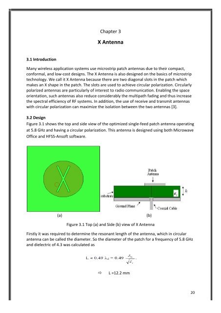
3.2 Design<br />
Figure 3.1 shows the top and side view of the optimized single-‐feed patch antenna operating<br />
at 5.8 GHz and having a circular polarization. This antenna is designed using both Microwave<br />
Office and HFSS-‐Ansoft software.<br />
(a) (b)<br />
Figure 3.1 Top (a) and Side (b) view of X Antenna<br />
Firstly it was required to determine the resonant length of the antenna, which in circular<br />
antenna can be called the diameter. So the diameter of the patch for a frequency of 5.8 GHz<br />
and dielectric of 4.3 was calculated as<br />
ð� L =12.2 mm<br />
20