Master Thesis
Master Thesis
Master Thesis

You also want an ePaper? Increase the reach of your titles
YUMPU automatically turns print PDFs into web optimized ePapers that Google loves.
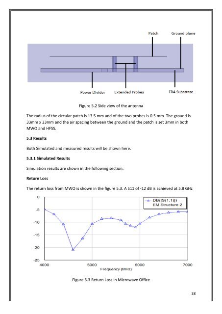
Figure 5.2 Side view of the antenna<br />
The radius of the circular patch is 13.5 mm and of the two probes is 0.5 mm. The ground is<br />
33mm x 33mm and the air spacing between the ground and the patch is set 3mm in both<br />
MWO and HFSS.<br />
5.3 Results<br />
Both Simulated and measured results will be shown here.<br />
5.3.1 Simulated Results<br />
Simulation results are shown in the following section.<br />
Return Loss<br />
The return loss from MWO is shown in the figure 5.3. A S11 of -‐12 dB is achieved at 5.8 GHz<br />
Figure 5.3 Return Loss in Microwave Office<br />
38